Fluidmesh 4200 FIBER Manual
Fluidmesh 4200 FIBER
Installation and Configuration Manual
Edition 1.6 (Firmware V8.3)

Table of Contents
1. HAZARDOUS CONDITION WARNINGS ........................................................... 6
1.1. Water Ingress Hazard ............................................................................. 6
1.2. Radio-Frequency Transmission Hazard .................................................... 7
1.3. Optical Radiation Hazard ........................................................................ 8
1.4. Hot Surfaces Hazard ............................................................................... 9
2. Reporting Mistakes And Recommending Improvements ................................... 10
3. Getting Started ............................................................................................... 11
3.1. Introduction ........................................................................................... 11
3.1.1. Fluidmesh 4200 FIBER ................................................................. 11
The Fluidmesh 4200 FIBER Radio Transceiver .................................. 11
Introduction ..................................................................................... 11
Unit Function And Throughput Speed ............................................... 12
Data Throttling ................................................................................ 12
MPLS Protocol ................................................................................ 12
Unit Configuration ........................................................................... 12
Role Adaptability ............................................................................. 12
Environmental Rating ...................................................................... 13
Product Specifications ..................................................................... 13
Transceiver And Gateway Unit Power Consumption .......................... 13
3.2. Fluidmesh Architecture ......................................................................... 14
3.2.1. Overview ..................................................................................... 14
Wireless Network Architectures ........................................................ 14
The FluidMAX TDMA Protocol ......................................................... 14
3.2.2. Fluidmesh Technologies ............................................................... 15
Prodigy .......................................................................................... 15
RACER .......................................................................................... 16
3.2.3. Point-To-Point Wireless Bridge ...................................................... 16
3.2.4. Mesh Network Architecture ........................................................... 17
3.2.5. Point-To-Multipoint Architecture With FluidMAX .............................. 18
3.3. Fluidmesh Network Addressing ............................................................. 20
3.3.1. Bridge IP Addressing ................................................................... 20
3.3.2. Unit Identification And Addressing ................................................. 20
Mesh- And Bridge-Capable Radio Transceiver Identification ............... 20
Operating The Unit In Mesh Point Mode Or Mesh End Mode .............. 21
Network Addressing ........................................................................ 22
Fluidmesh Radio Transceivers ................................................... 22
Connecting And Configuring An Ethernet Edge Device ...................... 23
Fluidmesh Radio Transceivers ................................................... 23
4. Hardware Installation ..................................................................................... 24
4.1. Fluidmesh Hardware Installation ............................................................ 24
4.1.1. Installing The Fluidmesh 4200 FIBER ............................................ 24
Environmental Rating And Unit Roles ............................................... 24
Installation Hardware ....................................................................... 24
4.1.2. Fluidmesh 4200 FIBER Status And Link LEDs ............................... 24
Unit And Link Quality Status ............................................................ 24
Boot Sequence ............................................................................... 25
4.1.3. Supplying Power To The Fluidmesh 4200 FIBER ............................ 25
Connecting Power To The Fluidmesh 4200 FIBER ............................. 26
DC IN, LAN And Fiber-Optic Ports .............................................. 26
4.1.4. Rebooting The Firmware And Resetting The Unit To Factory
Defaults ............................................................................................... 27
Fluidmesh 4200 FIBER
© Fluidmesh Networks LLC Page 2 of 180

Device Firmware Reboot ................................................................. 27
Resetting The Unit To Factory Settings ............................................. 28
4.1.5. Suitability For Outdoor Installation ................................................. 28
4.2. Connecting The Fluidmesh Fluidmesh 4200 FIBER To A Network And
Antennas .................................................................................................... 29
4.2.1. Terminal Assignments For Power And Data Connectors .................. 29
M12 A-Coded ................................................................................. 29
M12 A-Coded (Five-Pin) ............................................................ 29
M12 A-Coded Eight-Pin (Pre-September 2016 Only) ................... 30
M12 X-Coded ................................................................................. 32
XCO / SFP ..................................................................................... 33
Connecting Fiber-Optic Connectors To SFP Modules ................... 34
4.2.2. Connecting A DC IN Power Source To The Unit ............................. 35
4.2.3. Connecting LAN Cables To The Unit ............................................. 36
M12X LAN Cable ............................................................................ 36
4.2.4. Connecting An XCO-Standard Duplex Fiber-Optic Cable To The
Unit ...................................................................................................... 38
4.2.5. Connecting The Antennas To The Fluidmesh 4200 FIBER .............. 42
QMA Antenna Connections .............................................................. 42
5. Using The Fluidmesh Partner Portal ............................................................... 45
5.1. Accessing The Partner Portal ................................................................ 45
5.2. Enabling Two-Factor Authentication For Security .................................... 46
5.3. Administering Plug-In License Codes ..................................................... 48
5.4. Using The RACER™ Radio Configuration Interface ................................. 48
5.5. Viewing The Technical Documentation For Your Fluidmesh Device ........... 48
6. Device Configuration Using The Configurator Interface .................................... 50
6.1. Software And Hardware Prerequisites .................................................... 52
6.2. Accessing The Fluidmesh 4200 FIBER For Device Configuration ............. 52
6.2.1. Local Access And Login For Initial Configuration ............................ 53
6.2.2. Initial Configuration With The Unit In Provisioning Mode .................. 56
6.3. Switching Between Offline And Online Modes ......................................... 62
Uploading A Device Configuration File From RACER ............................... 63
6.4. General Settings ................................................................................... 65
6.4.1. The General Mode Window .......................................................... 65
Changing The Operational Mode ...................................................... 66
Changing The Operational Mode On A Mesh Network-Capable
Unit .......................................................................................... 66
Changing The Prodigy Version ......................................................... 67
Changing The LAN Parameters ........................................................ 68
6.4.2. Wireless Settings ......................................................................... 69
Modifying The Wireless Settings ...................................................... 69
Important Considerations For Wireless Settings ................................ 71
Point-To-Point And Point-To-Multipoint Considerations ....................... 71
Co-Location Considerations ............................................................. 72
Channel Width Considerations ......................................................... 72
Dynamic Frequency Selection Considerations ................................... 73
6.4.3. Antenna-Alignment Tools And Physical Statistics ............................ 74
6.4.4. Spectral Analysis ......................................................................... 77
6.5. Network Control .................................................................................... 78
6.5.1. Ping Softdog ................................................................................ 78
6.5.2. FMQuadro ................................................................................... 80
FMQuadro™ For Mesh Network-Capable Devices ............................. 80
Plotting And Interpreting The Wireless Links ............................... 80
Using And Interpreting The Wireless Link Information Display ...... 83
Fluidmesh 4200 FIBER
© Fluidmesh Networks LLC Page 3 of 180

Interpreting Device Warnings And Wireless Link Warnings ........... 86
Using The Address Summary Table ............................................ 86
Adding An Aerial Map To The FMQuadro View ............................ 87
6.5.3. Fluidity Quadro™ ......................................................................... 89
Fluidity Quadro For Mesh-End Devices ............................................. 89
Plotting And Interpreting Static And Mobile Device Information ..... 90
Using The Vehicles Table ........................................................... 92
Adding An Aerial Map To The Fluidity Quadro View ..................... 94
6.5.4. Advanced Tools ........................................................................... 95
Using The Ping Test Tool ................................................................. 95
Using The Bandwidth Test Tool ........................................................ 96
Using The Path MTU Discovery Tool ................................................ 97
6.6. Advanced Settings ................................................................................ 97
6.6.1. Advanced Radio Settings ............................................................. 97
Using The FluidMAX Management Setting ........................................ 98
Using The Max TX Power Setting ..................................................... 99
Using The Select Antenna Gain Setting .......................................... 100
Using The Data Packet Encryption Setting ...................................... 100
Using The Maximum Link Length Setting ........................................ 101
6.6.2. SFP Settings ............................................................................. 102
6.6.3. Static Routes ............................................................................. 103
6.6.4. Whitelists And Blacklists ............................................................. 104
6.6.5. Multicast ................................................................................... 107
Multicast Management For Mesh Network-Capable Devices ............ 107
6.6.6. SNMP Configuration ................................................................... 110
Using SNMP V2c ........................................................................... 111
Using SNMP V3 ............................................................................. 112
6.6.7. Wireless Access Point Configuration ............................................ 114
6.6.8. RADIUS Configuration ................................................................ 119
6.6.9. NTP Configuration ..................................................................... 122
6.6.10. L2TP Configuration .................................................................. 123
6.6.11. VLAN Settings ......................................................................... 124
VLAN Configuration ...................................................................... 124
Rules For Packet Management ...................................................... 126
6.6.12. Fluidity Settings ....................................................................... 127
Handoff Logic And Rate Adaptation Settings ................................... 130
6.6.13. Miscellaneous Settings ............................................................. 131
6.7. Management Settings ......................................................................... 133
6.7.1. View Mode Settings ................................................................... 133
6.7.2. Changing The Administrator Username And Password ................. 136
Enabling Remote Access To The Unit By Telnet .............................. 138
6.7.3. Overwriting And Upgrading The Unit Firmware ............................. 138
6.7.4. Plug-In Management .................................................................. 140
6.7.5. The Device Status View ............................................................. 144
The Device Status Window ............................................................ 144
6.7.6. Saving And Restoring The Unit Settings ...................................... 146
6.7.7. Resetting The Unit To Factory Defaults ........................................ 147
Rebooting The Unit ....................................................................... 148
6.7.8. Logging Out .............................................................................. 148
6.7.9. Viewing The End-User License Agreement .................................. 149
7. Software Plug-Ins ........................................................................................ 151
7.1. Available Plug-Ins ............................................................................... 151
7.2. Plug-In Management Procedures ......................................................... 155
7.2.1. Plug-In Activation ....................................................................... 155
Fluidmesh 4200 FIBER
© Fluidmesh Networks LLC Page 4 of 180

7.2.2. Deactivating An Active Plug-In .................................................... 157
7.2.3. Reactivating A Deactivated Plug-In ............................................. 159
7.2.4. Exporting And Uploading Multiple Activation Codes ...................... 160
7.2.5. Sharing License Codes And Accepting Shared License Codes ...... 162
8. Troubleshooting .......................................................................................... 163
8.1. I Cannot Get The Log-In Screen .......................................................... 163
8.2. I Cannot Log In To The RACER Interface ............................................. 163
8.3. I Forgot The Administrator Password ................................................... 163
8.4. The Wireless Link Is Poor Or Non-Existent In Bridge Mode .................... 164
9. Electrical Power Requirements ..................................................................... 165
10. Heat Radiation Data .................................................................................. 167
11. Federal Communications Commission (FCC) Radio Interference Statement ... 168
12. Notices And Copyright ............................................................................... 171
13. Fluidmesh End-User License Agreement ..................................................... 173
13.1. Preamble ......................................................................................... 173
13.2. Notice .............................................................................................. 173
13.3. Definitions ........................................................................................ 173
13.4. License Grant ................................................................................... 174
13.5. Uses And Restrictions On Use ........................................................... 174
13.6. Open-Source Software ...................................................................... 175
13.7. Termination ...................................................................................... 176
13.8. Feedback ......................................................................................... 176
13.9. Consent To Use Of Data .................................................................... 176
13.10. Warranty Disclaimer ........................................................................ 177
13.11. Limitation Of Liability ....................................................................... 177
13.12. Exclusion Of Liability For Emergency Services .................................. 178
13.13. Export Control ................................................................................ 178
13.14. General .......................................................................................... 179
14. Contact Us ................................................................................................ 180
Fluidmesh 4200 FIBER
© Fluidmesh Networks LLC Page 5 of 180
1. HAZARDOUS CONDITION WARNINGS
All Fluidmesh products are designed with safety in mind. However,
improper use of electronic and/or RF-emitting devices and/or their control
software has potential to cause serious injury and/or property damage. To
avoid such injury and damage, install, configure and operate Fluidmesh
products only if you are properly qualified to do so.
If any Fluidmesh hardware unit breaks down or malfunctions, emits smoke
or an unusual smell, if water or other foreign matter enters the unit
enclosure, or if the unit is dropped onto a hard surface or damaged in any
way, power off the unit immediately and contact an authorized Fluidmesh
Networks dealer for assistance.
If you are adjusting and/or controlling a Fluidmesh device using control
software such as the RACER™ interface or the device's local Configurator
interface, do not make configuration changes unless you know with
certainty that your changes will not negatively impact people or animals in
the vicinity of the device and its antennas.
1.1. Water ingress hazard
CAUTION
In all circumstances where the Fluidmesh 4200 FIBER will be
installed in an outdoor location, it is compulsory to mount the
Fluidmesh 4200 FIBER inside an FM-SHIELD auxiliary
mounting kit.
The FM-SHIELD auxiliary mounting kit is a proprietary
Fluidmesh solution, and is designed specifically to assure the
long-term durability and reliability of compatible radio
transceivers that have been installed in outdoor environments.
If you need further information regarding the recommended
usage of FM-SHIELD, contact your Fluidmesh Networks
representative.
Relevant technical specifications for FM-SHIELD can be found
in the Fluidmesh FM-SHIELD installation manual.
Fluidmesh 4200 FIBER
© Fluidmesh Networks LLC Page 6 of 180

1.2. Radio-frequency transmission hazard
WARNING
Non-ionizing radio frequency (RF) transmissions can be
hazardous to human and animal health.
In sufficient quantity, RF radiation is capable of causing
radiation burns, tissue damage and other injuries. Keep a safe
distance from all RF-radiating devices such as antennas, when
such devices are powered ON. Never stand in line with a
powered RF-radiating device.
Before activating any device capable of transmitting RF
signals, make sure that all persons and animals are protected
from possible RF exposure.
Make sure that all RF feeds are securely connected to an
appropriate antenna. Never activate any RF-capable device
that is not connected to an antenna.
Fluidmesh 4200 FIBER
© Fluidmesh Networks LLC Page 7 of 180
1.3. Optical radiation hazard
WARNING
If any Fluidmesh hardware device is equipped with one or
more fiber-optic transceiver modules, it is classified as a Class
1 laser product. It may use laser-emitting components and/or
very high-intensity light sources.
Do not look directly at the input/output end of the unit's SFP
connector, or at the input/output end of any fiber-optic cable.
Fiber-optic systems frequently use high-intensity light from
laser or LED sources that may cause temporary or permanent
blindness.
For additional guidance regarding the safe use of laser-based
and LED-based fiber-optic technology, refer to ANSI Z136.2
(Safe Use of Optical Fiber Communication Systems Utilizing
Laser Diode and LED Sources).
IMPORTANT
The Fluidmesh 4200 FIBER is not shipped from the factory
with fiber-optic transceivers installed unless the fiber-optic
transceivers were specified as part of the purchase order.
To gain fiber-optic capability, the unit must be equipped with a
separate fiber-optic transceiver module.
Fluidmesh 4200 FIBER
© Fluidmesh Networks LLC Page 8 of 180
1.4. Hot surfaces hazard
WARNING
The outer surfaces of transceiver and gateway unit enclosures
may become hot during normal operation. During normal
operation, do not touch or handle the unit enclosure without
personal protective equipment.
Fluidmesh 4200 FIBER
© Fluidmesh Networks LLC Page 9 of 180

2. REPORTING MISTAKES AND
RECOMMENDING IMPROVEMENTS
You can help improve this manual.
If you find any mistakes, or if you know of a way to improve the
procedures that are given, please let us know by E-mailing your
suggestions to [email protected].
Fluidmesh 4200 FIBER
© Fluidmesh Networks LLC Page 10 of 180

3. GETTING STARTED
3.1. Introduction
3.1.1. Fluidmesh 4200 FIBER
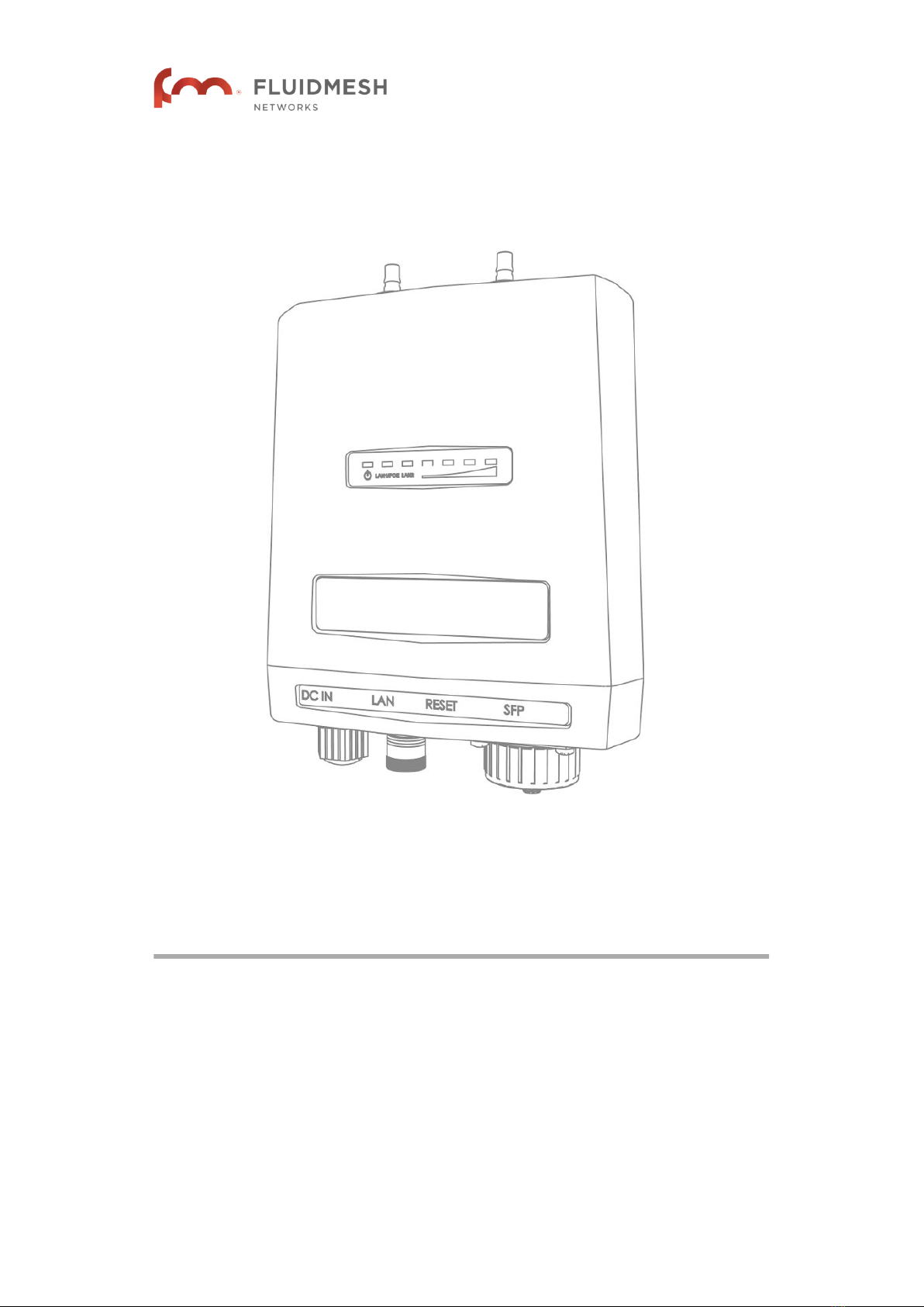
The Fluidmesh 4200 FIBER radio transceiver
Introduction
The Fluidmesh 4200 FIBER is designed to operate in the sub-6 GHz
range as a static-mount wireless data link. In non-technical terms, this
means it is designed to function as an intermediate radio link between a
core wired and/or fiber-optic data network, and a sub-network. The unit is
specifically designed for enhanced survivability in harsh environments
such as seaside ports, railways and mines. It provides reliable service in
high-speed applications (for example, servicing extremely fast-moving
trains) and must be connected to one or more external antennas. The unit
is designed primarily for mobility applications based on Fluidity
technology, in which specialized antennas need to be deployed (for
example, train-to-ground, automated mining vehicles, industrial
automation and similar applications).
The Fluidmesh 4200 FIBER is configured as a multiple input/multiple
output (MIMO) 2x2 radio transceiver. In a 2x2 scenario, two separate
spatial streams are transmitted by one transceiver unit, and are available
to be re-combined by the radio chipset of a second transceiver unit.
Fluidmesh 4200 FIBER
© Fluidmesh Networks LLC Page 11 of 180

IMPORTANT
XCO-standard transceiver modules and XCO-type duplex
fiber-optic connectors can easily be sourced as off-the-shelf
parts.
If you experience difficulty in sourcing or ordering fiber-optic
parts or accessories, please contact your local Fluidmesh
Networks representative for assistance.
Unit function and throughput speed
The unit is designed to handle mission-critical video, voice, and data with
extremely high reliability. It can be fitted with a single XCO-type SFP fiber-
optic transceiver module to create fiber-optic connected point-to-point,
point-to-multipoint or mesh network links, with real throughput of up to 100
Mbps under optimal wireless link conditions.
Data throttling
The unit's FluidThrottle functionality allows you to specify the maximum
amount of data throughput the unit will be required to handle at any time.
The unit's throughput capacity can be upgraded to different levels using
software plug-ins.
MPLS protocol
Two different Multi-Protocol Label Switching (MPLS)-based protocol
versions can be chosen. If a newer network is being built or upgraded, the
advanced Prodigy 2.0 protocol can be selected to boost performance. If
an older network incorporating Fluidmesh components is being upgraded,
the Prodigy 1.0 protocol with limited functionality can be selected to
guarantee compatibility. Prodigy uses a traffic optimization algorithm that
allows every Fluidmesh radio to assign a specific priority level to every
forwarded data packet.
Unit configuration
The unit is compatible with Fluidmesh RACER™. This is a centralized,
web-based interface that allows you to configure, monitor, and
troubleshoot the unit (and in certain cases, the entire wireless network) in
real time, without the need for any offline software. In cases where an
initial connection cannot be made to the internet, the unit can be
configured using a built-in offline Configurator interface.
Role adaptability
The unit is equipped with FluidMAX. This is a software technology that
allows you to easily change the role of the unit, so that it is able to function
as part of a Point-to-Point, Point-to-Multipoint, or Mesh network
architecture without having to replace physical hardware. The unit can use
Fluidmesh 4200 FIBER
© Fluidmesh Networks LLC Page 12 of 180

time-division multiple access (TDMA), or carrier sense multiple access
(CSMA) protocols.
Environmental rating
The unit is certified for outdoor usage, equipped with vibration-proof
connectors, and designed for fast installation and enhanced reliability in
harsh environments.
Product specifications
For detailed product specifications, refer to the product data sheet for the
Fluidmesh 4200 FIBER.
Transceiver and gateway unit power consumption
In service, Fluidmesh transceiver units and gateway units consume
electrical power at the rates given in the table below.
IMPORTANT
In service, transceiver and gateway units will consume power
at various levels between the quoted lower limit and upper
limit, depending on data traffic load, signal strength,
environmental conditions such as line-of-sight and atmospheric
moisture, and other factors.
Note that the power consumption of transceiver units tends to
be affected in inverse proportion to the unit temperature (in
other words, power consumption tends to rise when the
temperature of the unit falls, and the other way around).
Table 1. Power consumption figures (transceiver units)
Unit series Minimum power
consumption
Nominal power
consumption (typical
conditions)
Maximum power
consumption
(realistic system-
design
assumption)
FM PONTE
50
4 Watts 6 to 7 Watts 10 Watts
FM 1200
VOLO
4 Watts 6 to 7 Watts 10 Watts
FM 1300
OTTO
8 Watts 10 to 12 Watts 15 Watts
FM 3200-
series
4 Watts 6 to 7 Watts 10 Watts
FM 4200-
series
4 Watts 6 to 7 Watts 10 Watts
FM 3500
ENDO
8 Watts 10 to 12 Watts 15 Watts
Fluidmesh 4200 FIBER
© Fluidmesh Networks LLC Page 13 of 180

Unit series Minimum power
consumption
Nominal power
consumption (typical
conditions)
Maximum power
consumption
(realistic system-
design
assumption)
FM 4500-
series
8 Watts 10 to 12 Watts 15 Watts
FM 4800 13 Watts 15 to 17 Watts 20 Watts
Table 2. Power consumption figures (gateway units)
Unit Maximum power consumption (realistic system-design
assumption)
FM 1000 60 Watts
FM 10000 275 Watts (redundant AC power supply)
250 Watts (non-redundant AC power supply)
3.2. Fluidmesh architecture
3.2.1. Overview
Wireless network architectures
Depending on the network design and the type of components used, the
Fluidmesh 4200 FIBER can be used to create wireless network
architectures, including:
• Point-to-point (P2P) links.
• Point-to-multipoint (PTMP) sectors.
• Mesh networks.
• Mobility networks.
• Mixed networks that are capable of using any combination of types
listed above.
The FluidMAX TDMA protocol
Individual radio transceivers can easily be assigned different roles within
the same network, using Fluidmesh’s patented FluidMAX™ technology. A
typical example of a general network architecture that uses a combination
of Fluidmesh components is shown below:
Fluidmesh 4200 FIBER
© Fluidmesh Networks LLC Page 14 of 180
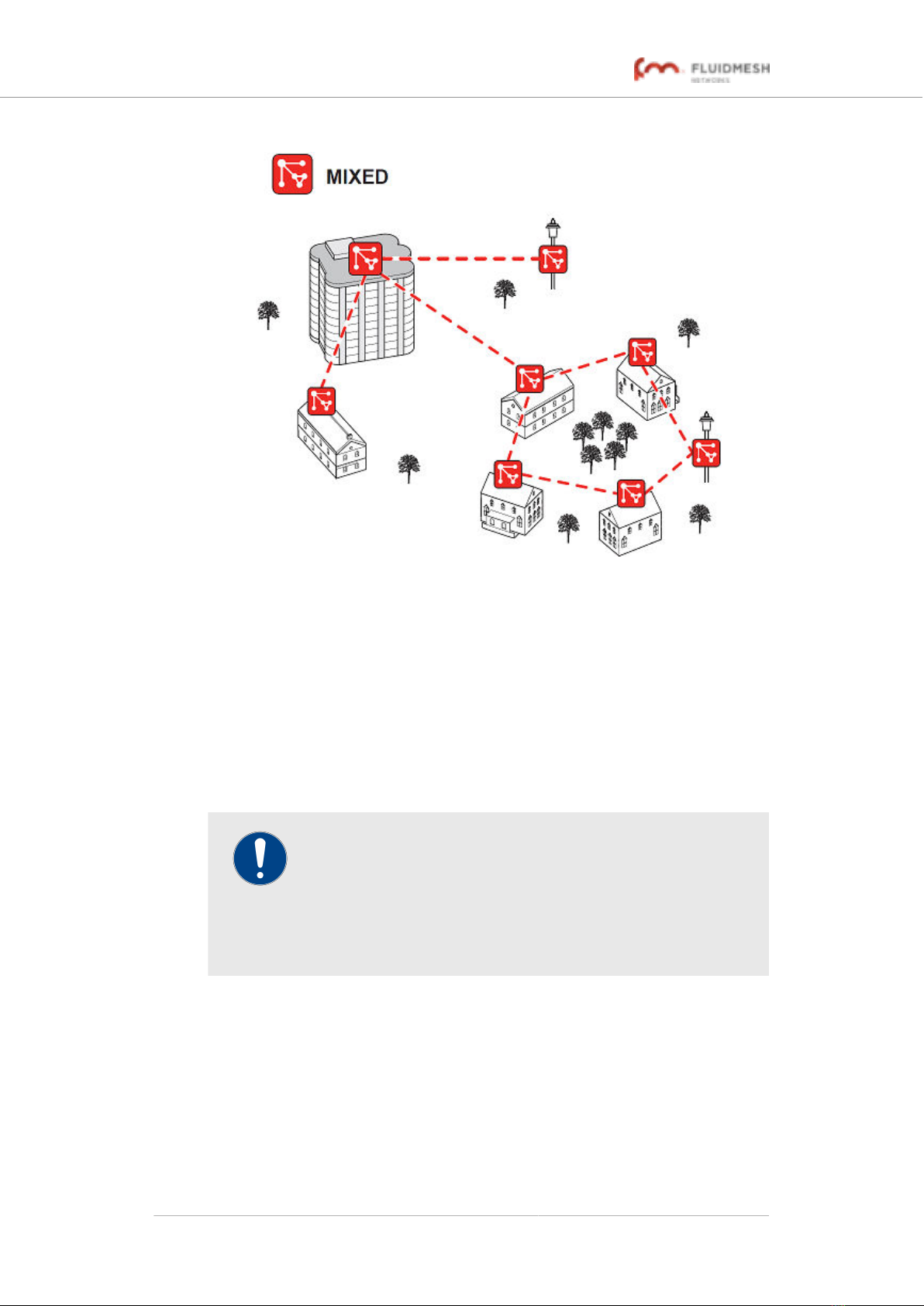
FluidMAX™ enables high-performance deployments of outstanding
flexibility. The following section shows how to build point-to-point, point-to-
multipoint and mesh networks using Fluidmesh products.
3.2.2. Fluidmesh technologies
Prodigy
Prodigy is Fluidmesh's proprietary implementation of the Multi-Protocol-
Label-Switching (MPLS) standard.
IMPORTANT
A Fluidmesh device only features Prodigy selection if the
installed Prodigy engine includes the selection feature.
Fluidmesh devices that are designed to operate exclusively in
Bridge Mode (in other words, in point-to-point configuration) do
not feature Prodigy.
Prodigy 2.0 offers greatly improved performance compared to Prodigy 1.0.
New features include Fluidity (through software plug-ins), traffic
engineering, and advanced Quality of Service (QoS).
Note that Prodigy 2.0 is only compatible with firmware versions 6.5 and
higher.
Fluidmesh 4200 FIBER
© Fluidmesh Networks LLC Page 15 of 180

IMPORTANT
Prodigy 1.0 and Prodigy 2.0 are not compatible with each
other. Do not implement the two protocol versions within the
same network.
If you are expanding an existing network using new Fluidmesh
hardware components, make sure that all components are
compatible with each other by:
1. Upgrading all network components within the same
network to firmware version 6.5 or higher, and:
2. Configuring all network components within the same
network to operate using either Prodigy 1.0 or Prodigy
2.0.
Use of Prodigy 1.0 is only recommended if the network
contains older Fluidmesh devices that are not compatible with
Prodigy 2.0.
Select the Prodigy version you need by using the General
Mode page of the Configurator interface.
RACER
RACER™ is Fluidmesh's web-based configuration portal. It is the primary
interface with which to configure Fluidmesh radio devices.
You can operate RACER using any internet-connected computer with a
web browser.
IMPORTANT
For a detailed description of the differences between RACER
and the local Configurator interface, refer to “Device
configuration using the configurator interface” (page 50).
3.2.3. Point-to-point wireless bridge
A point-to-point wireless bridge allows two local networks to communicate
with each other. A simplified example is shown in Figure 1 (page 17).
In context of the overall network architecture, the two local networks are
called network segments.
Fluidmesh 4200 FIBER
© Fluidmesh Networks LLC Page 16 of 180
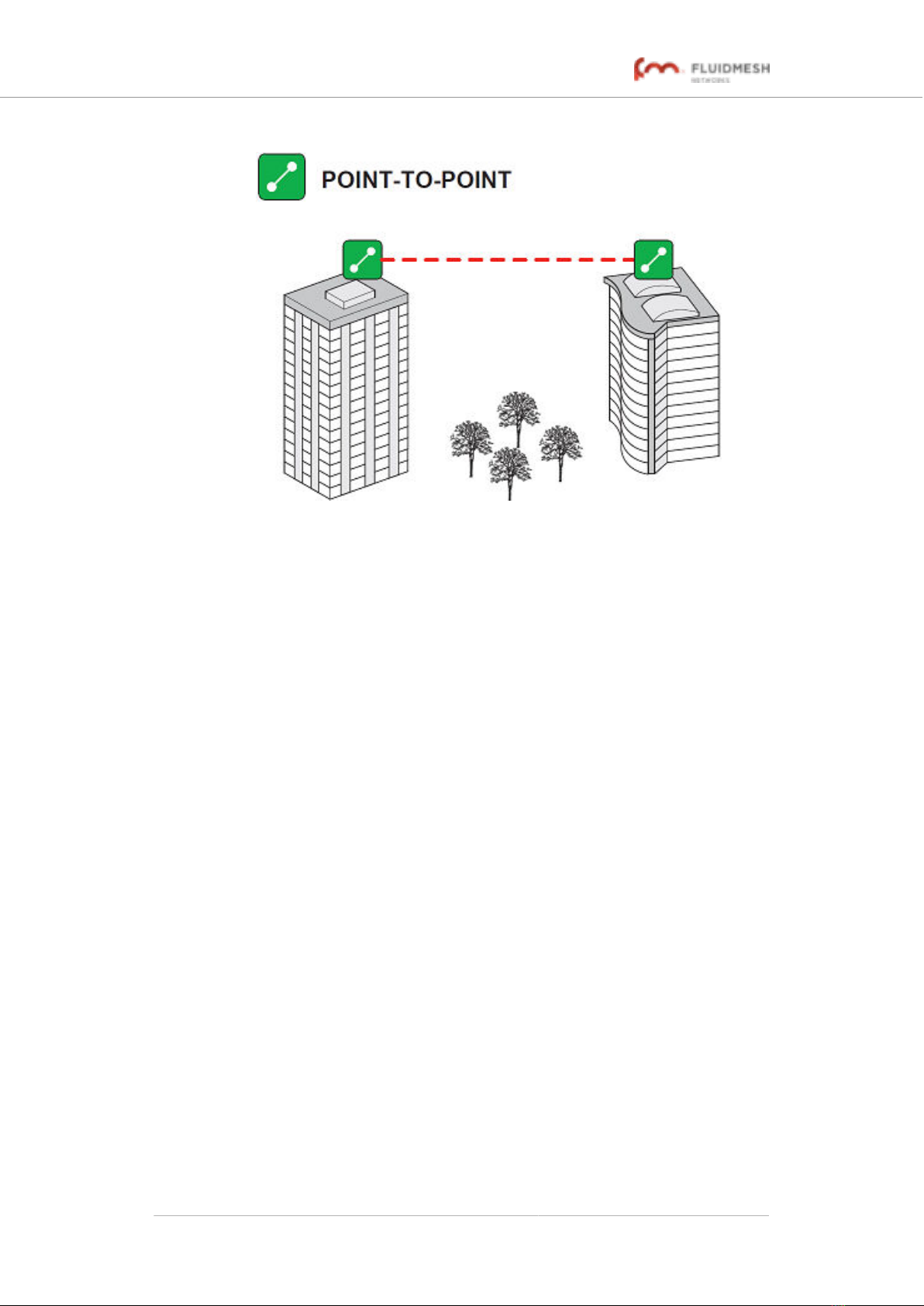
Figure 1. Point-to-point network architecture
All network activity that takes place on wireless bridges is 'transparent' to
the network hosts. In other words, a wireless bridge forwards packets
from one network segment to another according to a 'Forwarding table'.
The forwarding table is built by learning the network topology from
analysis of incoming traffic.
In this configuration, no explicit interaction takes place between the
wireless bridge and the network hosts. The network segments on either
side of the wireless bridge share the same IP subnet. Therefore, each
network host must use a unique IP address within the subnet.
3.2.4. Mesh network architecture
Fluidmesh Networks offers wireless networking solutions that are based
on the mesh networking architecture, but can also fill more traditional
networking roles if needed. This allows substantial reliability and flexibility
advantages when compared to traditional wireless solutions.
A simplified example of a wireless mesh network is shown in Figure 2
(page 18). In such a network, every Fluidmesh hardware component
transmits the data packets that come from the components directly linked
to it.
In a reliable mesh network with an acceptable amount of redundancy,
every stream of data packets may reach the base station through any of a
variety of paths. The Fluidmesh 4200 FIBER is designed to act as an
'intelligent router' that is able to forward packets coming from other
Fluidmesh components in real time, based on an optimal, software-
determined path. In addition, the absence of any single point of failure
greatly increases reliability when compared to any other wireless or wired
data-transmission technology.
Fluidmesh 4200 FIBER
© Fluidmesh Networks LLC Page 17 of 180
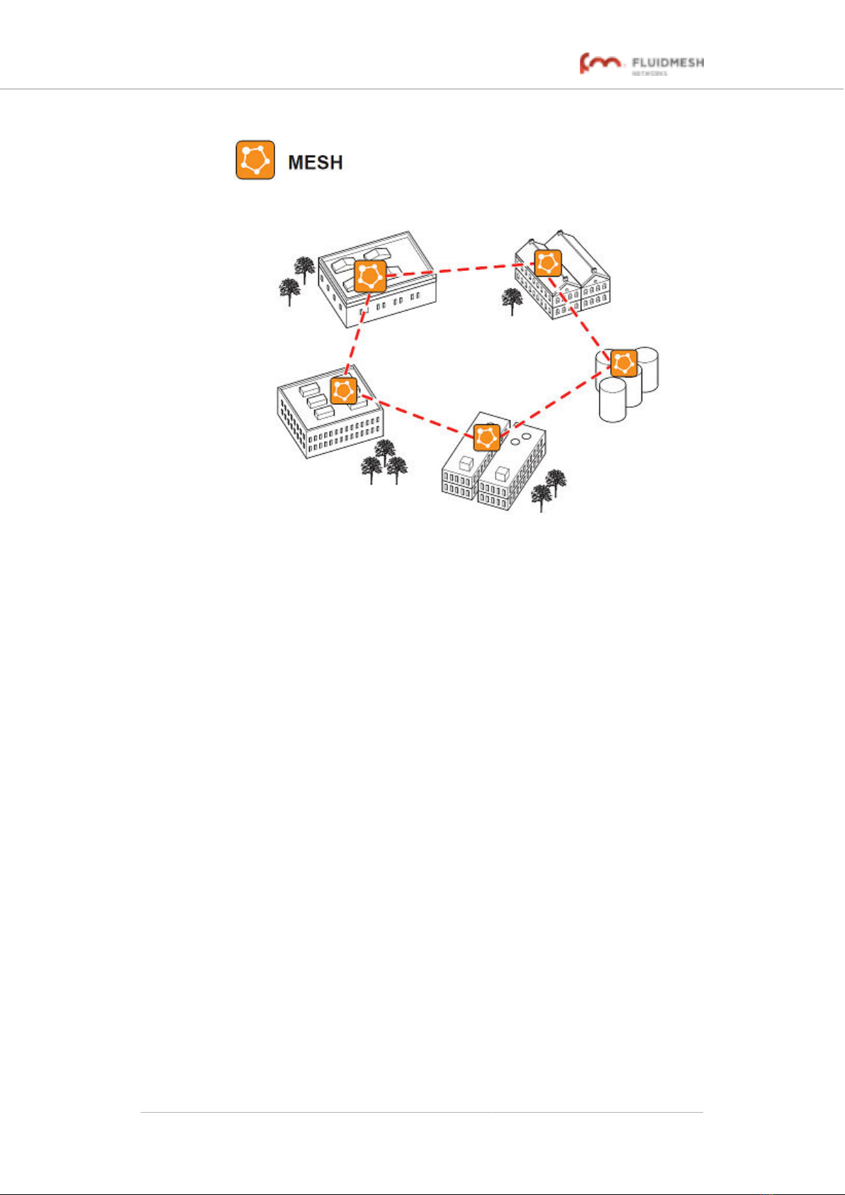
Figure 2. Fluidmesh Mesh Networking Architecture
3.2.5. Point-to-multipoint architecture with FluidMAX
FluidMAX™ is Fluidmesh's proprietary and patented communications co-
ordination protocol for wireless mesh networks.
The FluidMAX protocol is based on the concept of point-to-multipoint
network architecture (Figure 3 (page 19)) with improved features and
capabilities that allow the technology to meet or exceed the needs of the
security and industrial automation industries.
Fluidmesh 4200 FIBER
© Fluidmesh Networks LLC Page 18 of 180
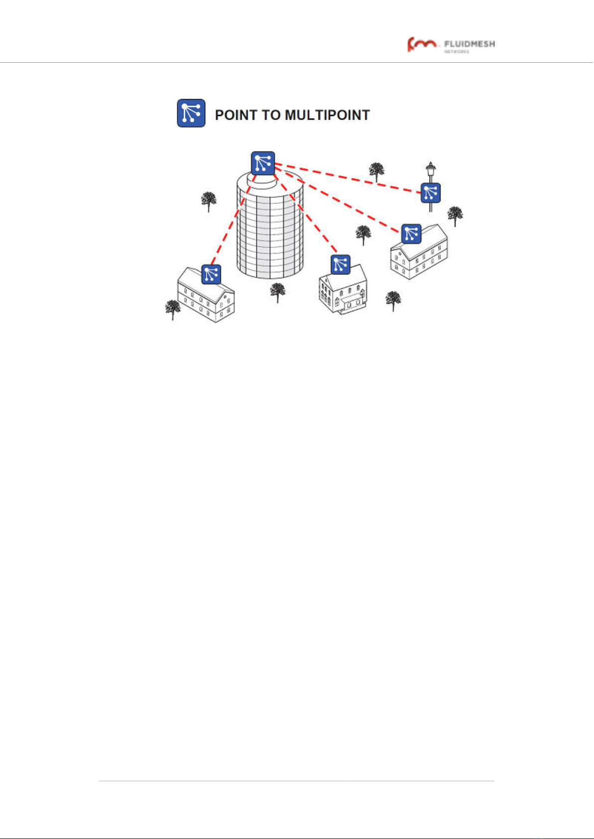
Figure 3. Typical point-to-multipoint networking architecture
FluidMAX is based on a centralized Media Access Control (MAC)
protocol. It allows point-to-multipoint networks to be created by facilitating
quick, reliable communications between Fluidmesh radio transceiver units
that are part of the same network. Using FluidMAX technology, a
Fluidmesh unit can be used as the center point of a star topology in a
point-to-multipoint network arrangement using sector antennas, or using
antenna splitters connected to more than one directional antenna. The
Fluidmesh unit at the center of the star topology is assigned a Master role,
co-ordinating communications to and from all other units (which are
assigned Slave roles). Assuming a default communication channel width
of 40 MHz, the MAC protocol used by FluidMAX is capable of supporting
data throughput of up to 150 Mb/s.
Provided that the sum of the data throughput requirements of all slave
units in the star topology is less than or equal to 150 Mb/s, FluidMAX
technology allows an increased data throughput rate per slave unit. This
allows the number of installed slave units to be reduced.
FluidMAX operates automatically and is fully integrated within the mesh
network architecture. By continuously monitoring the network topology,
installed Fluidmesh units are able to automatically use the FluidMAX MAC
protocol, or remain in the initial mesh operating mode. No additional
configuration is needed to enable the FluidMAX features, as the
communication protocol is automatically chosen by FluidMAX, based on
the detected network topology.
Fluidmesh 4200 FIBER
© Fluidmesh Networks LLC Page 19 of 180
3.3. Fluidmesh Network Addressing
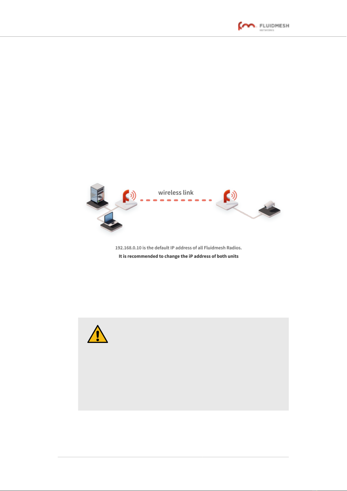
3.3.1. Bridge IP addressing
If needed, the Fluidmesh 4200 FIBER can be operated in Bridge mode.
This creates a single point-to-point connection between two network
segments. A simplified example of a Bridge mode connection is shown
in Figure 4 (page 20).
As shipped from the factory, the wired ethernet ports of all Fluidmesh
hardware components are assigned the same default IP address of
192.168.0.10/24.
No default IP address is associated with the wireless interface.
Figure 4. Wireless network architecture (bridge configuration)
3.3.2. Unit identification and addressing
Mesh- and bridge-capable radio transceiver identification
CAUTION
This section contains theoretical explanations of the underlying
concepts behind mesh network addressing, and is intended for
use by qualified network engineers only.
• For specific instructions on Fluidmesh hardware
installation, see “Hardware installation” (page 24).
• For specific instructions on how to configure a
Fluidmesh radio transceiver unit using the configurator
interface, see “Device configuration using the
configurator interface” (page 50).
Regardless of its configuration and operating mode, every Fluidmesh
radio transceiver is shipped from the factory with a unique unit
identification (ID) number. This number always takes the following form:
Fluidmesh 4200 FIBER
© Fluidmesh Networks LLC Page 20 of 180
Table of contents


