Fluke Calibration 5322A-LOAD User manual

PN 5006848
July 2018
©2018 Fluke Corporation. All rights reserved.
All product names are trademarks of their respective companies. Specifications are subject to change without notice.
Fluke Corporation
P.O. Box 9090
Everett, WA 98206-9090
U.S.A.
Fluke Europe B.V.
P.O. Box 1186
5602 BD Eindhoven
The Netherlands
ООО «Флюк СИА
Й
ЭС»
125167, г. Москва,
Ленинградский проспект дом 37,
корпус 9, подъезд 4, 1 этаж
1
5322A-LOAD
High Voltage Load Adapter
Instructions
Introduction
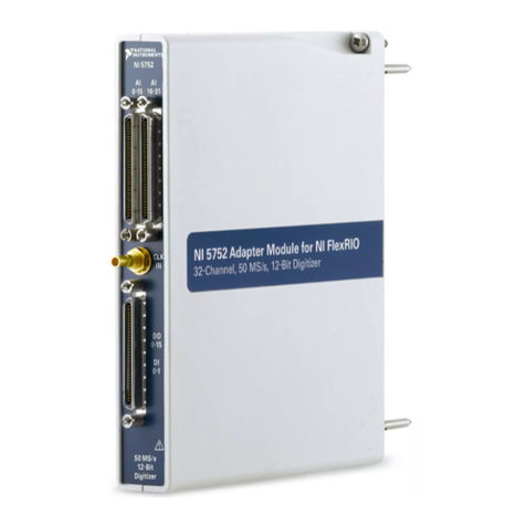
The 5322A-LOAD High Voltage Load Adapter (the
Product) loads a hipot tester to create leakage current
during hipot tester calibration with the 5322A
Multifunction Electrical Tester Calibrator (hereafter the
Calibrator). As shown in Figure 1, the Product consists
of nine power-rated resistors configured to provide
nine resistance taps from 10 kΩto 10 MΩ. Each of the
nine resistors in the Product can be put in parallel with
any other resistor. To do this, use the supplied high-
voltage jumper leads to short the resistor's red terminal
to the resistor’s corresponding black terminal.The
Product withstands a maximum voltage of 1.2 kV to
5.5 kV, depending upon the selected resistor.
HI
LO
10k 25k 50k 100k 250k 500k 1M 5M 10M
Output
Ieu004.eps
Figure 1. Load Schematic
XW Warning
To avoid possible electric shock or
personal injury, use this Product only as
specified in this Instruction Sheet or the
5322A Operators Manual.
How to Contact Fluke Calibration
To contact Fluke Calibration, call one of the following
telephone numbers:
•Technical Support USA: 1-877-355-3225
•Calibration/Repair USA: 1-877-355-3225
•Canada: 1-800-36-FLUKE (1-800-363-5853)
•Europe: +31-40-2675-200
•Japan: +81-3-6714-3114
•Singapore: +65-6799-5566
•China: +86-400-810-3435
•Brazil: +55-11-3759-7600
•Anywhere in the world: +1-425-446-6110
To see product information and download the latest
manual supplements, visit Fluke Calibration’s website
at www.flukecal.com.
To register your product, visit
http://flukecal.com/register-product.

5322A-LOAD
Instructions
2
Symbols
The symbols used in these instructions and on
the Product are shown in Table 1.
Table 1. Symbols
Symbol Description
XWARNING. HAZARDOUS VOLTAGE. Risk
of electric shock.
WWARNING.RISK OF DANGER. Risk of
electric shock.
Consult user documentation.
)Certified by CSA Group to North American
safety standards.
PConforms to European Union directives.
Conforms to relevant Australian Safety and
EMC standards.
AC (Alternating Current)
.Protective conductor terminal
Earth
Fuse
Conforms to relevant South Korean EMC
Standards.
~
This product complies with the WEEE
Directive marking requirements. The affixed
label indicates that you must not discard this
electrical/electronic product in domestic
household waste. Product Category: With
reference to the equipment types in the
WEEE Directive Annex I, this product is
classed as category 9 "Monitoring and
Control Instrumentation" product. Do not
dispose of this product as unsorted
municipal waste.
Preparing for Operation
The Product (see Figure 2) comes with a power line
adapter (to run the cooling fans), a ground cable, three
shorting cables, and these instructions.
The power line adapter comes with five mains plug
adapters that are compatible with different power plug
configurations.
Prior to use:
1. Select the appropriate plug adapter that matches
the local power mains outlet.
2. Attach the plug to the power line adapter. The
power line adapter is now ready for use with the
Product.
3. Once you place the Product on top of the
Calibrator, connect the grounding cable between
the Product’s rear-panel ground terminal and the
rear-panel ground terminal of the Calibrator. See
the grounding cable connection in Figure 3 where
the rear of the Product is shown.
XW Warning
To prevent possible electrical shock, fire,
or personal injury:
•Make sure that the ground terminal on
the rear of the Product is connected to
the ground (GND) terminal on the rear
of the Calibrator. Any application with
non-grounded housing is strictly
prohibited.
•Use only the shrouded high-voltage
banana plug jumpers that are supplied
with this Product to connect resistor
values. Connect the black terminal first
and disconnect the black terminal last
when you connect resistors.

High Voltage Load Adapter
Preparing for Operation
3
WCaution
To prevent damage to the Product, make
sure that the vents on the bottom of the
Product and the fan exhaust vents are
clear of obstructions for proper cooling.
Connect one end of the power line adapter to the
mating power input connector socket on the rear panel
of the Product and the other end to the mains power
outlet.
WCaution
Failure to have the fans operating may
lead to over heating and component
failure.
Push the rear-panel switch to the “I” side of the switch
to turn on the cooling fans. A light on the front panel
illuminates and indicates that power is on. Turn off the
power switch when the Product is no longer being
used.
Ieu001.eps
Figure 2. 5322A-LOAD Front Panel
PROTECTIVE
EARTH (GROUND)
POWER INPUT
12V
10 VA MAX.
NO USER SERVICEABLE PARTS CONTAINED WITHIN.
HAZARDOUS VOLTAGES PRESENT. DO NOT REMOVE COVERS.
SAFETY WARNING
DISCONNECT POWER AND SIGNAL LEADS
BEFORE SERVICING.
READ MANUAL BEFORE USE.
REFER SERVICETO QUALIFIED PERSONNEL.
FLUKE CORPORATION
www.fluke.com
DURING USE,
TERMINAL MUST BE
CONNECTED TO THE
PROTECTIVE EARTH
OF THE 5320A
Rear
Ground Cable
USB
ehq101.eps
Figure 3. Grounding Cable Connection

5322A-LOAD
Instructions
4
Use the Load for Leakage Current
Tests
Select the load resistor based on the appropriate
voltage amplitude for the test or the value
recommended in the hipot tester’s calibration
procedure. A load resistor is connected to the Output
terminals when a resistor's red and black terminals
are shorted together using a high-voltage shrouded
banana jumper lead.
See Paralleling Resistors for making additional
resistance values. See the 5322A Operators Manual
for more detailed application information.
WCaution
To avoid damage, never exceed the
maximum rated voltage, power, and
current limit of the Product.
Usage Limits for Safe Operation for Each
Load Resistor
Safe operation of the Product depends on the amount
of voltage and the length of time it is applied to the
Product. For the 10 kΩ, 35 kΩ, 50 kΩ, 100 kΩ, and
250 kΩresistors, there are time limits where the
higher-voltage levels can be safely applied. This is
graphically shown in Figure 4 for the 10k, 25k, 50k,
100k, and 250k resistors.The maximum voltages can
be applied for up to 3 minutes for these resistors. Due
to self heating, exceeding the 3-minute limit for high
voltages can cause both degradation of performance
and a permanent shift in the resistor value. However,
reduced-voltage levels can be safely applied for
increasing longer times. At specific levels, sustained
voltages can be applied indefinitely. The other
resistors (500k, 1M, 5M and 10M) do not have a time
limit for the maximum voltage (5500V). See Figure 4.
Safe Area
0
1000
2000
3000
4000
5000
6000
110100
Time (min)
Voltage (V)
250 k
100 k
35k/50k
10k
ehq101.eps
Figure 4. Safe Area Chart
Example
The 100 kΩresistor can withstand 5500 V for
3 minutes while it can withstand 4000 V for
60 minutes or longer.
Paralleling Resistors
The Product can output additional values by placing
combinations of the nine resistors in parallel as shown
in Table 2.
To place resistors in parallel, short together
combinations of the given resistors’ red and black
terminals using the supplied high-voltage shrouded
banana jumper leads. For example, to parallel the
10 kΩand 25 kΩresistors, short the 10 kΩred and
black terminals, and the 25 kΩred and black
terminals. This places these two resistors in parallel at
the Product Output terminals. The resultant output is
7.14 kΩ, for a 70 mA leakage current at 500 V, as
shown in Table 2.
In Figure 5, the 10k Ohm, 25k Ohm, and 50k Ohm
resistors are in parallel, giving an output of 6.25 kΩ.
HiPot
Tes te r
Ieu003.eps
Figure 5. Leakage Current Test Connection
The maximum applicable working voltage for parallel
combinations is the maximum voltage of the resistor
with the lowest voltage rating.
WCaution
Do not exceed the specified
voltage limits of any given
resistor.

High Voltage Load Adapter
Paralleling Resistors
5
Example
To set up a leakage current of 3 mA at a test voltage
of 1000 V, find the row in Table 2 for 3 mA and then
select the desired test voltage. For 1000 V, parallel
the 500 kΩand 1 MΩresistors to make a 333.33 kΩ
output.
Table 2. Parallel Combination of Resistors Versus Voltage Versus Current
Current
(mA) 500 V 1000 V 2000 V 5000 V
0.05 10M - - -
0.1 5M 10M - -
0.2 - 5M 10M -
0.3 - 5M, 10M - -
0.4 - - 5M -
0.5 1M - - 10M
0.6 1M,5M - 5M, 10M -
1 500k 1M - 5M
1.5 500k, 1M - - 5M, 10M
2 250k 500k 1M -
2.5 250k, 1M - - -
3 250k, 500k 500k, 1M - -
4 - 250k 500k -
5 100k 250k, 1M - 1M
6 100k,500k 250k, 500k 500k, 1M 1M, 5M
7 100k, 250k 250k, 500k, 1M - -
8 100k, 250k, 500k - 250k -
10 50k 100k 250k, 1M 500k
12 - 100k,500k 250k, 500k -
14 - - 250k, 500k, 1M -
15 50k, 100k - - 500k, 1M
16 - 100k, 250k, 500k - -
20 25k 50k - -
30 25k, 50k 50k, 100k - -
50 10k - - -
70 10k, 25k - - -
80 10k, 25k, 50k - - -

5322A-LOAD
Instructions
6
Performance and Verification Test
With normal operation, verify the resistance values of
the Product at least once per year. Also, verify the
load resistor if there is a possibility of the resistance
values changing due to excessive heating or power
dissipation.
To verify the electrical performance of the Product,
use one of these test methods to ensure the load
resistors are within specification:
•Voltage Test Method - Use voltage and current
levels that ensure that the resistors dissipate a
reasonable power as they are verified.
•Mutlimeter Test Method - Use a multimeter to
measure the load resistance.
Both methods check to see if it is within 10 % of the
nominal value. The multimeter test uses minimal
voltage and current levels, dissipating negligible
power when measuring the resistance values of the
load resistance.
Either test method can be used, but Fluke Calibration
recommends the voltage method as it verifies the
resistance value while the resistor disipates actual
power – similar to the normal usage of the Product.
The voltage method signal levels are based on
capabilities of the recommended voltage calibrators.
These levels use voltages up to 1 kV. It is possible
and acceptable to test using other sources to test at
higher voltages, but staying within the limits of the
Product’s safe area of operation.
Table 3 lists the load resistance nominal value for
each load resistor terminal.
To use the voltage test method, apply a test voltage
across each resistance, between the respective input
and COM terminals. The resulting current through the
resistor is measured, and the value of the resistance
is calculated. Use a calibrator as the precision-voltage
source. Use a multimeter to measure the current.
Figure 6 shows the test equipment setup. Refer to
Table 3 for the respective sourced voltage level
settings and the nominal currents to be measured.
Note
Fluke Calibration recommends a Fluke
5520A or 5500A Calibrator as a source
for the voltage method due to its output
voltage/current capabilities. Fluke
Calibration recommends a Fluke
8845A Digital Multimeter (or
equivalent) for measurements with
either test method.
For the voltage test method, test each resistor as
follows:
1. Apply the recommended voltage (Vs) at power
mains frequency (either 50 Hz or 60 Hz) between
the terminal for the resistor being measured and
the COM terminal.
2. Measure the current (Im) flowing through the load.
3. Calculate the resistance (RL) by dividing the
sourced voltage by the measured current
(RL=Vs/Im).
The calculated resistance should be within 10 % of
the nominal resistance value found in Table 3.
Repeat steps 1 through 3 for each load resistor
terminal and adjust the applied voltage per Table 3.
For the alternative multimeter test method, measure
each resistor as follows:
1. Place the probes of a multimeter between the
selected resistor input (red) terminal and the COM
terminal.
2. Read the measured resistor using the resistance
mode of the multimeter, and note the value.
3. Ensure the measured value is within 10 % of the
nominal resistance.
Repeat steps 1 through 3 for each load resistor
terminal per Table 3.

High Voltage Load Adapter
Performance and Verification Test
7
POWER
I
O
0•
123
456
789
ENTER
M
k
mVHz
FIELD
EDIT
/
+
F
OPR EARTH EXGRD SCOPE MENU
PREV
SHIFT
RESET
CE
SETUP
REF
NEW
TC
MEAS
¡F
µ
n
p
W
dBm sec
¡CA
MULT
x
DIV
÷
MODES
MORE
STBY
HI
LO
TRIG
GUARD
TC
20A
NORMAL AUX
5520A CALIBRATOR
SCOPE
OUT
V, , ,RTD A, -SENSE, AUX V
20V PK MAX
20V PK MAX
5320A-LOAD
1200V MAX
140 W MA X
2000V MAX
110 W M AX
2000V MAX
80W MAX
5500V MAX
300W MAX
5500V MAX
120 W MAX
5500V MAX
60W MAX
5500V MAX
30W MAX
5500V MAX
6 W MAX
COM
10 k 35k 500k 1M50k 100 k 250k 5M
100 m A 40 mA 10 mA 4 mA 1mA
POWER
20 V MAX
8846A
6-1/2 DIGIT PRECISION MULTIMETER
0.20100 mA~
DCV ACV DC I ACI TRIG
FREQ
PERIOD
TEMP ZERO
INSTR
SETUP
MEAS
SETUP
RANGE
F1 F2 F3 F4 F5
BACK
MEMORY
ANALYZE
INPUT SENSE
HI
LO
FRONT
REAR
10 A
1V
400
mA
4
W
HI
LO
2W/4W
V
300V
FUSED
1000V CAT I
600V CAT II
Ieu002.eps
Figure 6. Test Equipment Connections for Voltage Test Method
Table 3. 5322-LOAD Resistance Verification Values
Nominal
Resistance
Value
Voltage Method – Verifying the Load Resistances while under Power Alternative DMM
Verification
Method
Externally
Applied Test
Voltage at
mains
Frequency
Nominally
Required Test
Current
Measured
Current
Calculated
Resistance
RL=Vs/Im
(±10 % of nominal)
Measured
Resistance
(±10 % of nominal)
10 kΩ200 V ac 20 mA
25 kΩ315 V ac 9 mA
50 kΩ300 V ac 6 mA
100 kΩ600 V ac 6 mA
250 kΩ1000 V ac 4 mA
500 kΩ1000 V ac 2 mA
1 MΩ1000 V ac 1 mA
5 MΩ1000 V ac 0.2 mA
10 MΩ1000 V ac 0.1 mA

5322A-LOAD
Instructions
8
Replaceable Parts
Table 4 lists the replaceable parts for the Product.
Table 4. Replaceable Parts
Description Fluke PN
POWER ADAPTER 100-240V AC, 12 V DC, with five plug adapters 3132484
GROUNDING CABLE 3132491
TEST LEAD, HIGH VOLTAGE, BANANA, 25 cm set of 3 (RED) 5006907
General Specifications
Power supply voltage.............................................. AC adapter 100-240 V, output voltage 12 V @ 0.4 amps min.
Warm-up time ......................................................... Not applicable
Specifications confidence level............................... 99 %
Temperature
Operating Temperature .......................................... 5 °C to 40 °C
Recommended Calibration Temperature (Tcal) ..... 23 °C
Storage Temperature.............................................. -20 °C to +70 °C
Altitude, Maximum
Operating................................................................ 3 050 m (10 000 ft)
Storage ................................................................... 12 200 m (40 000 ft)
Dimensions............................................................. 430 mm X 462 mm X 95 mm (16.9 in X 18.2 in X 3.7 in)
Weight (net) ............................................................ 3 kg (8 lb 4.5 oz)
Power Consumption ............................................... 5 W maximum
Safety class ............................................................ I according to EN 61010-1
Electrical Specifications
Total resistance range .................................................. 10 kΩto 10 MΩ
Number of specific resistance values........................... 9
Tolerance to Nominal Value ......................................... 10 % (One year, Tcal ±5 °C)
Maximum Ratings
Nominal Value Max. Voltage Max. Dissipation Power Max. Time at Maximum Power
10 kΩ1200 V 140 W Limited to 3 minutes (see Figure 4)
35 kΩ2000 V 110 W Limited to 3 minutes (see Figure 4)
50 kΩ2000 V 80 W Limited to 3 minutes (see Figure 4)
100 kΩ5500 V 300 W Limited to 3 minutes (see Figure 4)
250 kΩ5500 V 120 W Limited to 3 minutes (see Figure 4)
500 kΩ5500 V 60 W No limit
1 MΩ5500 V 30 W No limit
5 MΩ5500 V 5 W No limit
10 MΩ5500 V 3 W No limit
Table of contents

