Flying Penguin RC FPRC Zero User manual

E
Estim
a
W
T
Flyi
F
P
Bramp
t
www.f
l
flyingp
e
Sp
e
WingSpan
Fuselagele
n
mptyWeigh
t
a
tedFlying
W
W
ingArea:1
5
T
ransmitter:
4
ng
P
P
RC
t
on,Ontari
o
l
yingpengui
n
e
nguin@liv
e
e
cification
s
–42.75”(10
n
gth–30.5”(
t
–9.5‐10oz.
W
eight–20‐2
5
5
1sq.Inch(9
4
or5channe
P
eng
u
ZE
R
o
Canada
n
rc.com
e
.ca
s
85mm)
775mm)
(150‐160g)
5
oz.(320‐40
0
75sq.cm)
lwithflaps
u
in
R
R
O
0
g)
R
C

1|Page
INTRODUCTION
Introduction…………………………………………….…...1
Electronics&hardware…………………………..….…2
BuildingMaterials………………………………………...2
Tools……………………………………………………………..2
Assemblyinstructions
1.PowerCoreBaseAssembly…………………….….2
2.RearFuselageFrame………………..……….………7
3.CompleteFuselageFrame………….…..…..……..8
4.Hardwareinstallation………………………….…..11
5.FuselageCover………………………………………..13
6.FrontAccessCover...………………………….…….19
7.CanopyCover.………………….………………….…..21
8.Wings………………………………………………..…….25
9.Rudder/TailWing………………………………..…33
10.WingReinforcement………………………..……35
11.FitRudder/TailWing……………………..…….36
12.AirScoop/Rearpanels………………………….36
13.LandingGearOption……………..…..…………..38
14.FinalConnections………..…………………………39
PartsIndex………………….……………………………….40
1.YourFPRCZeroshouldnotbeconsidereda
toy,butratherasophisticated,workingmodel
thatfunctionsverymuchlikeafull‐sizeairplane.
AlthoughtheFPRCZEROisalight‐weight
model,justthesameasanyR/Cplane,itshould
stillbeflownwithcare.Evenwhileglidingat
slowspeeds,theFPRCZEROcouldpossibly
causeinjurytoyourselforspectatorsand
damageproperty.Ultimately,itisthe
modeller’sresponsibilitytoselectasuitable,
safeflyingarea.
2.YoumustassembletheFPRCZEROaccording
totheinstructions.Donotalterormodifythe
model,asdoingsomayresultinanunsafeor
unflyablemodel.
3.Bepatient.Youmusttakethetimetobuild
straight,trueandstrong.
4.YoumustuseanR/Cradiosystemthatisin
excellentcondition.
5.YoumustcorrectlyinstallallR/Candother
componentssothatthemodeloperates
correctlyonthegroundandintheair.
6.Youmustchecktheoperationofthemodel
beforeeveryflighttoinsurethatallequipment
isoperatingandthatthemodelhasremained
structurallysound.Besuretocheckconnections
oftenandreplacethemiftheyshowsignsof
wearorfatigue.
7.IfyouarenotalreadyanexperiencedR/C
pilot,youshouldflythemodelonlywiththe
helpofacompetent,experiencedR/Cpilot.
Remember:Takeyourtimeandfollowthe
instructionstoendupwithawell‐builtmodel
Thatisstraightandtrue.
Ifyouhavenotflownthistypeofmodelbefore,
werecommendthatyougettheassistanceof
anexperiencedpilotinyourR/Cclubforyour
firstflights.Ifyou’renotamemberofanR/C
club,yourlocalhobbyshophasinformation
aboutclubsinyourareawhosemembership
Includesexperiencedpilots.
CONTENTS
NOTE:
We, as the model designer, provide you
with top quality plans and detailed
instructions, but ultimately the quality of
your finished model depends on how you
build it; therefore, we cannot in any way
guarantee the performance of your
completed model, and no representations
are expressed or implied as to the
performance or safety of your completed
model.

2|Page
‐Motor:1200kv/250wbrushlesselectric
‐ESC:25ampbrushlessspeedcontroller
‐Battery:2200mAh3S11.1VLipoPack
‐Servos:(4x)9‐10gramdigitalmicroservos
‐Propeller:8x6Eor9x6E
‐ControlHorns(x4)
‐PushRods:1mmpianowire.(2x16”&2x3.5”)
‐Four(4x)sheetsfoamboard/foamcoreboard
3/16”x20”x30”(5x510x760mm)
‐One(1x)sheetposterboard
‐1/8”hobbyplywood
‐Two(2x)wooddowels.1/8”diameter,5”long.
‐PopsicleSticks
‐Velcroorrareearthmagnets
‐3/16”dia.orsquarecarbontube(optional)
‐X‐Actoknife&replacementblades
‐Utilityknife&replacementblades
‐Metalrulerorstraightedge
‐HotgluegunorCAAdhesive
‐Penorpencil
‐Drillandsmallwoodbits
‐ClearPackingTape
‐SmallScrewdrivers
Partsrequired:1‐5
1.Startwithpowercorebase(1)flatontable.
2.Applyathinlayerofwhiteschoolglueor
multi‐purposecraftgluetoshadedsurfaceas
shownabove.
3.Foldtopsurfaceover.Applingevenpressure,
holddownuntildry.
ElectronicsandHardware
BuildingMaterials
Tools
ASSEMBLYINSTRUCTIONS
1.POWERCOREBASE
ASSEMBLY
ADDITIONALREQUIREDITEMS

3|Page
4.Repeatsteps2and3forbottomsurface.
5.Nextwecancombineparts(2A‐2A)and
(2B‐2B).First,useapenorpenciltomarkthe
centerontheedgeasshownabove.Thiswill
helpustoalignthefuselagecoverlater.
6.Applyathinlayerofwhiteschoolglueor
multi‐purposecraftgluetoshadedsurfaceas
shownabove.Combineparts(2A),asthetwo
partsareidenticalalledgeswillalign.
7.Repeatsteps5and6for(2B).

4|Page
8.Repeatsteps5and6for(4A‐5A)and(4B‐5B).
Applygluetoframesection(5)firstthen
combinewith(4).
9.Framesections(5)areslightlysmallerthan
framesections(4)soalignthepartswiththe
squareopeningandbottomedge.
10.Preparepart(3).Removefoambetween
50%cutlinesleavingpaperonoppositeside.A
smallflattopscrewdriverisgoodforthis.
11.Placeabeadofglueinthespaceasshown
above.Foldthesidesothatitrestontopofthe
Adjacentsurface.
12.Repeatstep11fortheotherside.

5|Page
13.Nextwecancombineparts(1‐5)
14.Placeabeadofgluealongthetop/front
edgeofthepowercorebase(1).
15.Attachframesection(2A)topowercore
base(1).Alignwithfrontedgeandcenter.Make
sureframesection(2A)is90°topowercore
base(1),holduntildry.
16.Applygluetofrontedgeandbottomedges
ofpart(3)asshownabove.
17.Attachpart(3)totopofpowercorebase(1)
andtobackofframesection(2A)asshown
above.Aligntheinsidewallsofpart(3)withthe
squareopeninginfrontofframesection(2A).

6|Page
18.Applygluetobottomofframesections
(4A/5A)andtothebackedgesofpart(3)as
shownabove.Attachframesection(4A/5A)to
topofpowercorebase(1)withframesection
(5A)facingback.Alignwithsquareopeningin
part(3)andsidesofpowercorebase(1).
19.Applygluetobottomedgeofframesection
(2B).Attachtobottomofpowercorebase(1)as
shownabove.Alignwithfrontedgeandcenter.
Makesureframesection(2B)is90°topower
corebase(1),holduntildry.
20.Applygluetobottomedgeofframesection
(4B/5B).Attachtobottomofpowercorebase
(1)withframesection(5B)facingbackasshown
above.Viewfromthesideandalignwithframe
section(4A/5A)ontop.Makesureframe
section(4B/5B)is90°topowercorebase(1),
holduntildry.

7|Page
Partsrequired:6‐10
21.Applyathinlayerofwhiteschoolglueor
multi‐purposecraftgluetoonesideofframe
section(6).Combineparts(6),asthetwoparts
areidenticalalledgeswillalign
22.Usearulerandpenorpenciltocreatea
centerlineononesideofframesection(6).
Thissidewillfacethefrontoftheframe.
23.Applyasmallamountofglueoverthetab
slotinsideframe(7)asshownabove.Insert
framesection(6)withcenterlinefacingthe
front.
24.Repeatstep23forframesection(8).
2.REARFUSELAGEFRAME

8|Page
25.Applyasmallamountofglueintabslotsin
framesections(6)and(8)andtobackedgeof
sideframe(7)asshownabove.Insertsecond
sideframe(7)intoframesection(6)and(8).
26.Applyasmallamountofglueonthetop
centerofframesections(6)and(8)asshown
above.Insertframesupport(9)betweenframe
sections(6)and(8).
27.Repeatsteps26forframesupport(10)on
thebottomofframebetweenframesections
(6)and(8)asshownabove.
Partsrequired:powercorebaseassembly(1‐5),
rearfuselageframe(6‐10)andparts11‐14.
`
28.Applygluetoeachsideoftheslotinthe
backofthepowercorebase(1)aboutthewidth
ofthesideframe(7)asshownabove.
3.COMPLETEFUSELAGEFRAME

9|Page
29.Insertendsofsideframes(7)intoslotatthe
backofthepowercorebase(1).Makesurethe
powercorebaseandrearframetop/bottomis
orientedcorrectly.
Tip:Afoamblockcanbeusedtosteadythe
framefortherestofthebuildprocess.
30.Applygluetothebottomedgeofframe
section(11)andtobackedgeofpowercore
base(1)abovesideframes(7)asshownabove.
31.Framesection(11)shouldrestontopofside
frame(7)andbesidebackofpowercorebase
(1)andalignedwithedgeofsideframe(7).
32.Placeabeadofgluealongtheedgesof
servoplate(12)andacrossframesection(6)as
shownabove.Centerservoplate(12)with
framesection(6).

10|Page
33.Placeabeadofgluealongthebottomand
onesideedgeofframesupport(13)andside
frame(11)asshownabove.Inserttheframe
support(13)betweenframesection(11)&(6).
34.Repeatstep33forsecondframesupport
(13)tooppositesideasshownabove.
35.Preparebottomframesupports(14).Fold
partoveratthe50%cutasshownabove.Apply
gluetoinsideofframesupport(14)asshown
above.Placeflatontableandapplyalittle
downpressureuntildry,repeatforsecond
framesupport(14).
36.Testfitbatterybeforemovingtonextstep.
Enlargebatteryopeningifnecessaryandusea
penciltotracethesidesofthebatteryon
bottomofpowercorebase(1)forreference.

11|Page
37.Placeabeadofgluealongthetopofframe
support(14)andonthesideofframesection
(5B)asshownabove.Insertframesupport(14)
betweenframesections(5B)and(6).
38.Repeatstep37forsecondframesupport
(14)onoppositeside.
39.Placeasmallbeadofglueofonesideof
servoandattachsecondservofacingopposite
directionasshownabove.
40.Placeservowiresthroughopeninginservo
plate(12).Applyasmallamountofgluetothe
bottomoftheservotabsoneachsideofservos.
5.HARDWAREINSTALLATION

12|Page
41.Insertservosintoservoplate(12)asshown
above.
42.Gluetwostrawsbetweensmallholesin
framesections(6)and(8)asshownabove.
Thesewillhelpguidethecontrolrodtothe
servoslaterinthebuild.
43.Use1/8”hobbyplywoodoroldplasticgift
cardstocreatereinforcementplatesforthe
powercorelockingholes.
44.Gluethereinforcementplatestothetop
andbottomofthepowercorebase(1)as
shownabove.
45.Testfitbatteryandmarklocationofrearof
batteryonbottomofpowercorebase(1).
13|Pa
g
46.Glue
V
andtoun
section(
5
batteryh
a
duringfli
g
g
e
V
elcrostrips
t
dersideofsq
5
B)asshown
a
rnesstohol
d
g
ht.
t
opowercor
e
uareopenin
g
above.This
w
d
thebattery
e
base(1)
g
inframe
w
illcreatea
inplace
Part
s
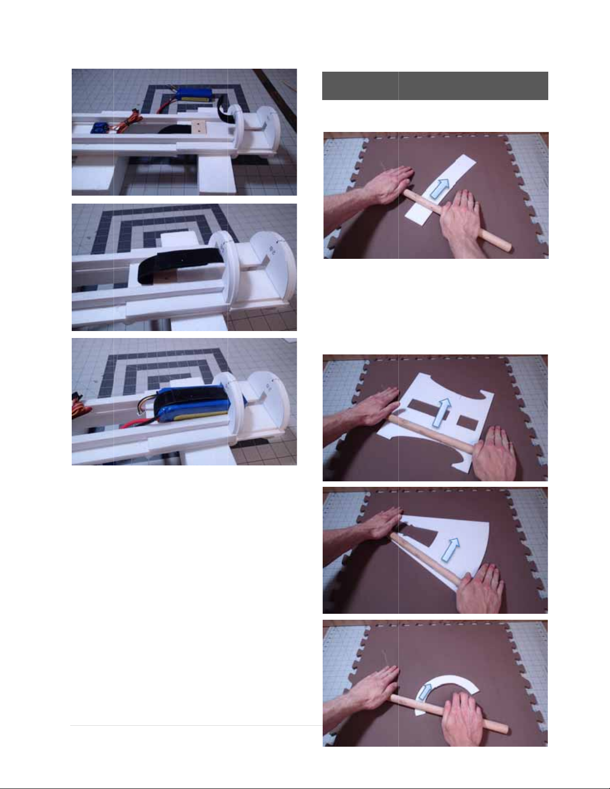
47.
P
Lay
t
cou
c
pin
r
inth
s
required1
5
P
reparethef
u
t
hepartsflat
c
hcushionw
o
r
ollacrossth
e
h
efoamassh
5.F
U
5
‐19
u
selagecove
r
onapieceo
f
o
rksbest)an
d
e
parttocrea
ownabovea
U
SELAGE
r
parts(15‐1
9
f
foam.(Afla
t
d
usingarolli
teanatural
c
ndbelow.
COVER
9
).
t
ng
c
urve

14|Page
48.Allfuselagecoverpartsshouldnowhavea
naturalcurveasshownabove.Thiswillmake
fittingoverthefuselageframemucheasier.
49.Dryfitfuselagecover(15)andmarkthe
endsatthebottomcenterandtrimifrequired.
50.Trimeachedgetocreateasnugfit.

15|Page
51.Applyasmallbeadofglueonthecenter/top
offramesections(2A)and(4A)asshownabove.
52.Centerthefuselagecover(15)between
framesections(2A)and(4A)andalignwith
frontasshownabove.Makesurethelonger
sideoffuselagecover(15)facestheback.
53.Togluetheframecover(15)totheframe
startwithoneside.Applygluetothetopedges
offramesection(2A)and(4A)andalongthe
sideedgeofthepowercorebase(1)asshown
above.Holdthefuselagecover(15)inplaceand
holduntildry.
54.Completethesidebyapplyinggluetothe
bottomsideedgesofframesections(2B)and
(4B)asshownabove.Holdthefuselagecover
(15)inplaceandholduntildry.
55.Nowmovetotheoppositesideandrepeat
theprocess.Startwiththetop,applyingglueto
theframesectionsandalongpowercorebase.
Foldoverandholduntildry.
56.Finishthebottomarea.Applygluetothe
sideframesandfuselagesection(15)edgeas
shownabove.Foldoverandholduntildry.

16|Page
FinishedFrontFuselageCover(15)
57.Nextwecanattachthecenterfuselage
cover(16).Usingthepreviousprocess;dryfit
first,trim(ifrequired),centerandgluetotopof
framesections.
58.Startwithonesideandgluethefronthalfof
thefuselagecoverfirst.Applygluetoedgeof
framesection(5A)andalongthesideframeas
shownabove.Foldoverandholduntildry.
59.Finishthebottomarea.Applygluetothe
sideedgeofframesection(5B)asshownabove.
Foldoverandholduntildry.
60.Repeatsteps58‐59tofinishthefronthalfof
fuselagecover(16).
61.Next,applygluetothesideofframesection
(6)andalongthesideframeasshownabove.
Foldoverandholduntildry.

17|Page
62.Finishthesidebyapplyinggluetotheside
edgeofframesection(6)asshownabove.Fold
overandholduntildry.
63.Repeatsteps61‐62tofinishthebackhalfof
fuselagecover(16).
64.Applygluetoonesideofsupportpart(17)
andinsertinsidefuselageasshownabove.
Centerwithfuselagecover(16)andrepeatfor
theotherside.
Thiswillhelptostrengthentheareawherewe
willinstallawooddowelforsecuringthewing.
65.Repeattheprocessforrearfuselagecover
(18).Dryfitfirst,trim(ifrequired),centerand
gluetotopofframe.
66.Doonesideatatime.Fronthalffirst,
startingwithtoparea.

18|Page
67.Gluethebottomareaofthefronthalffirst.
68.Placeasmallbeadofglueononeedgeof
thebottom/backoffuselagecover(18).Hold
togetheruntildry.Wipeaccessglueawaywitha
pieceofscrapfoam.
69.Applyabeadofgluealongthebackedgeof
thesideframeasshownabove.Holdthe
fuselagecovertotheframeuntildry.Repeatfor
theotherside.
70.Sandtheouteredgeofthenosefuselage
cover(19)toabevelshape.
Thebevelshapewillallowthecovertofitflush
tothefrontedgewhencurved.
71.Startatthetopapplyingasmallamountof
gluetothefrontedgeandusetheprocesswe
usedfortheotherfuselagecovers.Workyour
wayaroundaboutanincheachtime.

19|Page
Completedfrontfuselage
Completedrearfuselage
Completedsideandbottomviewoffuselage.
Partsrequired20‐22
72.Drawacenterlineonthesidesofcover
frame(21)andonthebottomofcover(22).
Measure3/4”or19mmfromthefrontedgeand
makeamarkasshownabove.Rollthecover
(22)aswedidforthefuselagecoverstocreate
anaturalcurve.
6.FRONTACCESSCOVER
Table of contents
Popular Toy manuals by other brands

MGA Entertainment
MGA Entertainment Little Tikes My First Mighty Blasters POWER... manual

Tamiya
Tamiya Lockheed P-38 F/G Lightning manual

Faller
Faller OCHSENHAUSEN STATION manual

RC Factory
RC Factory Flash 3D aerobatic EPP Building instructions

E-FLITE
E-FLITE Sukhoi SU-26m 480 Assembly manual

Mega Bloks
Mega Bloks Collector Series instructions


