The Train Department TD 52550 User manual
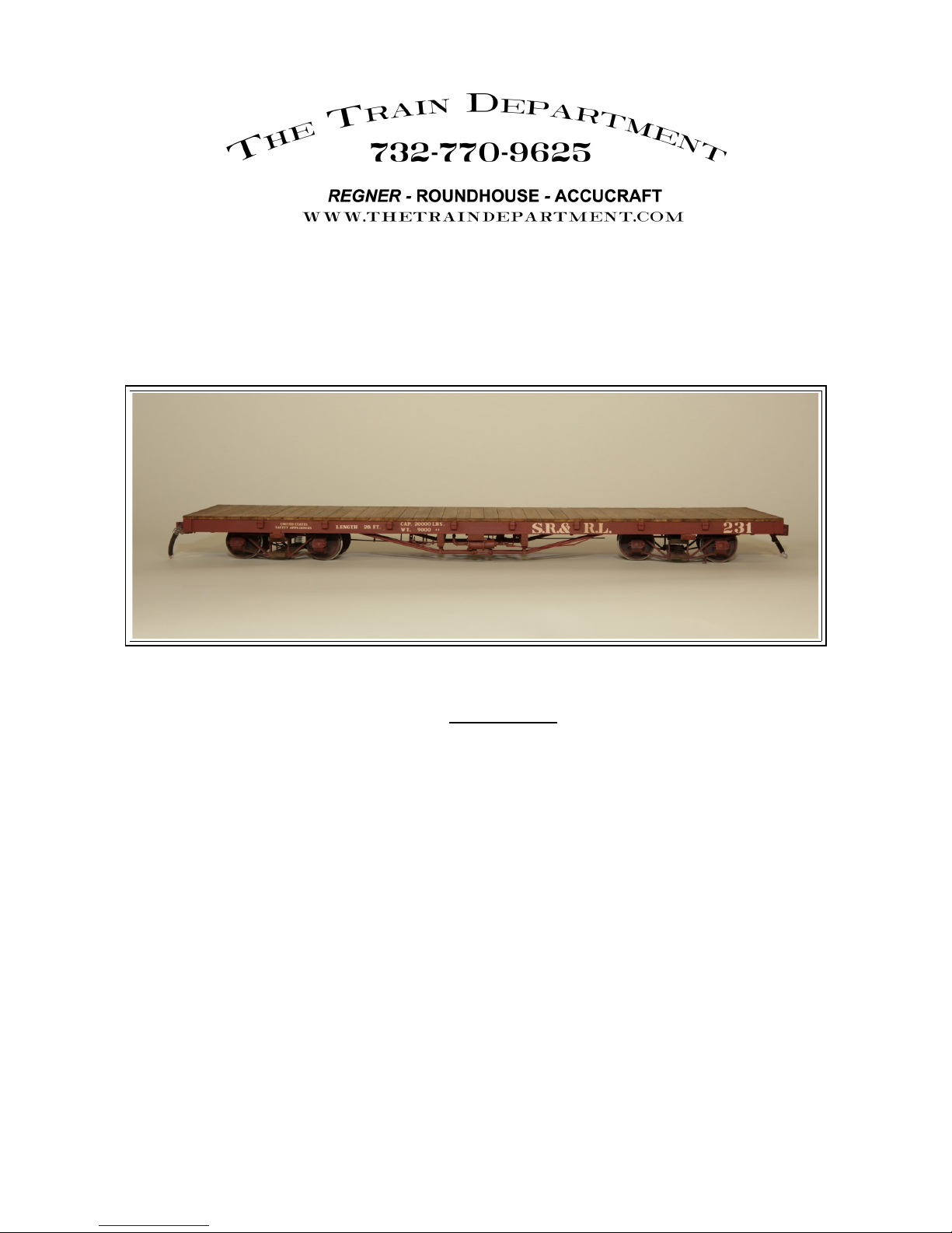
P/N TD 52550 S.R.R.L 28' FLAT CAR
Tools required
#0/1 Phillips driver
3/32” Nut driver
Pliers – Needle and Flatnose
Small Vise
Small ammer
Sandpaper 320/400 grit
Swiss files
ACC/CA Glue Medium or Gel
E6000 Adhesive
Wood Glue waterproof (Titebond III)
Solder/Flux for brass/steel. 95/5 lead/tin or similar solder
Drill bits - #60, 1/16”, 3/32”, 1/8”
Please read the instructions fully before starting.
Decide on paint and weathering before assembly as boards can be lightly distressed
prior.
For all of the instructions of the frame and the details I will be working with the deck upside down.
Meaning decking side on the bottom. This will insure all the details and parts are properly laid out.
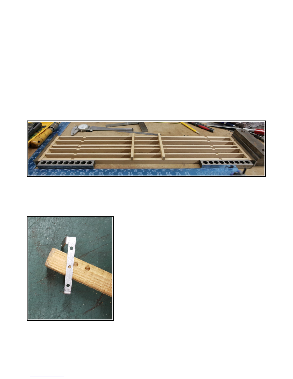
Using a wide flat work surface lay out the frame sills and end beams with the outer predrilled side sills
on the outside. The drilled holes will be towards the bottom. Using a grid or large square glue the end
beams to the sills. File or clean the dado joints as needed. Glue all but the 2nd sill to the end beams.
Do not g ue the 2nd si to the end beam yet as it needs to be removed for dri ing the inkage
support ater.
I have just laid in the needle beam for a frame spacer to keep the sills aligned. Do not glue them in
place yet.
With the frame cured, remove the Brake linkage support and using flat pliers or a vise bend the tabs
down at the scribed lines. Be sure to bend the correct way using the photo as a guide.
Depending on the flat car model you want to build measure
and markout the needle beams. 46” or 50” centered on the car
frame.
46” = sca e 3.358” 50” = sca e 3.650
Once marked and placed into position, using the brake linkage
support that you folded locate the mounting points of the #0
lag bolts using the holes to mark with a pencil. Drill with a
#60 drillbit in the needlebeam and sill that is loose on the
frame. (Use the frame images at the end of the instructions for
linkage layout and rough heights) The top of the bracket will
be just above needlebeam for the linkage clearance.
Once drilled you can glue in the 2nd sill to the frame and glue on the Needlebeams.

Next up we will mark out and bend the truss rods. You can build with full or short truss rods. As with
full truss rods you easily get frame and truck clearance issues I opted for short rods cut at the sill and
mounted. Drill/file the turnbuckle to accept the 3/32” trussrods. The end beams will be drilled 3/32” a
scale inch in (.072”) from the side sill centered on the end beam for a single rod. If you opt for a
double they are staggered rods 3.5” and 4.375” from the top of the end beam. Both are next to the sills
so I used those as my guide. If you are running full trussrods you can file and thread the ends for 2-56
thread for the supplied nuts. Otherwise I used a 2/56 bolt and nut on the washer as a made up NBW. I
also supplied laser cut square end washers if they suit your car build. ( I do have cast square end beam
washers available) Bend and fit the trussrods in place. To securely mount the trussrods as short, I used
small 1/16” cotter pins and used the head as the mount to drill and press into the side sills. DO not
dri through!
Glue in the 2 truck mounting blocks ( Qty 2 - 0.5” tall/0.405” wide/1.25” long) between the center sills
centered at the small dado for the truck truss rod support.
Take the single wood block for the brake cylinder (0.25” tall/.0650” wide/ 1.330” long) and glue to the
outer and 2nd sill aligning the one edge to the center of the car. Block is glued to the right side of center.
Take the 2 buffer blocks ( 0.550” tall/.0.220” wide/ 1.350” long) and glue to the center of the end
beams. Using the plastic NBW drill and install 4 per side on the buffer blocks.
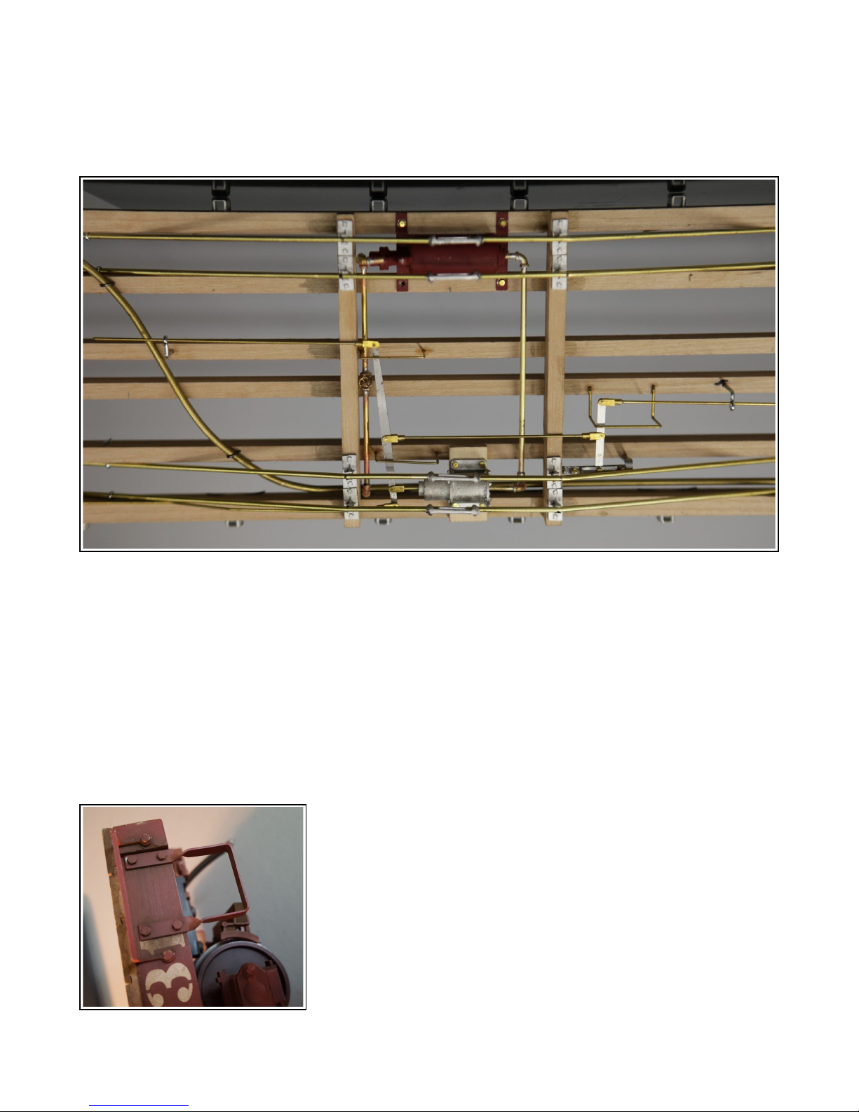
Brake Details
Using the photos as a guide all the hardware and details can be added. You can also use the book Two
Foot plans by M2FQ page 22, Can purchase from Gary Kohler. (Keep in mind the book drawing is a
view from above the car)
Take the brake cylinder and drill out the dimples for the #0 Lag. Use the holes as a guide and mark the
location to the block you glued on. Drill the wood #60 for the #0 Lag bolts. The brake cylinder will
need 2 holes drilled, One on the front a 1/16” hole for the linkage rod and the rear for the air line 3/32”
The Air tank is 2 parts to be glued together, use a strong glue suck as E6000 as it is a thicker bond.
Drill the rear of the tank for the air cylinder line 3/32” and the bottom of the triple valve inlet 3/32 for
the incoming line. Be careful as its a thin wall after drilled. Take the laser cut steel plate and use as
a drill guide for the air tank to mount the tank to the plate using 2 of the #2-32 self tapping screws.
Predrill 1/16” into the tank. Mount the plate and tank to the frame as shown using 4 - #0 lag bolts
predrilling the holes #60
All of the airlines and linkages are made up brass wire and Trackside details pipe fittings for the scale
look. This can be simulated or done fully as shown. The wire and castings are not included in the kit
but can be purchased easily.
1/8” for main airline from car end to end.
3/32” for the air valve and from the valve to the cylinder
3/64 brass wire for brake linkages from all levers
Trackside Details (TD-195) Clevis fittings
Trackside Details (TD-228) Large handwheel valve straight through
Trackside Details (TD-249) Large elbows for plumbing

All of the linkages can be soldered together for strength. The laser parts have 2 long levers, the one
just under 3” is for the flat car. The other is for the future boxcar and unused on this kit.
The short 3 hole lever for the pivot linkage mounts to the already installed pivot support. The top
prebent strap bolts and acts as a pivot housing. You will need to bend and adjust the strap to fit the
holes. Use the 3 – 0-80x .250” bolts/nuts to mount. I used again 1/16” cotter pins for the linkage
supports where they are cut and terminated before the trucks. All other linkage and hangers are 3/64”
brass wire bend to suit. The clevis I used a 1/32 brass wire used as a pin to the linkage.
The stake pockets are held in with the.028” wire supplied. Cut into 2” lengths and using a set of flat
pliers to prebend into a U. Mark the location and width of the bend on the plier nose using a casting to
get the right width. Insert the wire into the predrilled holes and pull to the pocket and bend over the
wire on the inside to lock in. You can either leave as is or use a drop of E6000 on each wire end. (Bend
the wire over securely with a screwdriver or something to give a sharp bend on the inside.)
To install the grab irons, remove from the sheet and bend the ends 0.350” from the round end into a
90degree bend. Mount 2 per side sill at each end. Mount one per end beam on the left side(keeping the
deck upside down) Lay the irons flush with the work table to mark and drill #60 the mounting for #0
lag bolts.
To install the steps remove the strips from the sheet and using a
vise or pliers bend at the notch unto a U shape. You will need to
mark and twist the tops to mount to the sills. Do this 4 times.
Mark and drill 4 #60 holes for #0 lags
Note that your steps wi not be f ush with the end beam.

The truck bearing mounts can be mounted to the frame with the 2-32 screws and predrilling 1/16”
Before mounting you will need to solder the large ring to the mount centered on the mounting hole. The
smaller ring will solder to the square plate that mounts to the truck. This makes up a truck bearing
pivot. Best not to paint but oil this surface. Drill the center truck mounting block 3/32” for the #6
mounting screws to be installed later.
Bend with pliers the ends for the trussrod plastic NBW. The ends will bend in to about 70degrees.
Using the E6000 glue in the large plastic NBW.
The square bearing can be glued/screwed or pinned to the truck top beam.
At this point the whole frame can be painted and gloss clearcoated. Be sure to take and cover the top
surface so you can glue the decking on after its decaled. Install the decals per the photos of the car you
are modeling or use the supplied images as a guide. Once the decals are dry, apply another gloss clear
coat then a final semigloss or matt clearcoat. This will ensure the decals are sealed and edges are not
longer visible.
Once the decals and details are all painted the decking can be added. Starting with a starter board start
to glue in shorter sections all the decking. You can also use a headless pin nailer. End with the last
board and trim to fit it needed.
Once the decking is dry you can install the brake wheel parts. Take
the T bracket and center the arm on the middle of the 2nd sill. Using
the #0 lags mount the bracket and the pawl. Using the short 3/32 wire
as a guide locate the lower bracket to the end beam and keep the
brakewheel perpendicular to the decking. The lower bracket needs to
be bent 90degrees and twisted as shown. Once mounted, mark the rod
and cut 3.5” then mark the location of the ratchet to be soldered on so
that the bottom of the rod is just 1/32” past the lower bracket. Glue on
the handwheel to the top. Paint to suit.
The anglecocks can be mounted to the bottom of the end beams aligning to the outside of the edge of
the 2nd sill. Use the supplied U strap to mount and glue in with E6000. Can also stake it in with some
1/32” wire bent into a U staple. Can join the plumbing pipe and the casting with some 5/32” K/S
tubing. Cut the rubber hose to about 2” and slip on the anglecock and insert the gladhand to the other
end.
The coupler housings are designed for 830/930 Kadee coupler. Use the short #6 screws and the single
nylon spacer as the bushing to mount the coupler. If using link and pin mount to suit the car.
Build the trucks per the instructions provided. To add the brakes, Mount the brake beams to the long
strips with the 2-32 self tapping screws. Using the strips as a guide mark and drill the lower brake
beam to center the brake supports. 2-32 screw to attach the strips from the top of the lower beam.
Glue on the brake shoes to the end of the beams.
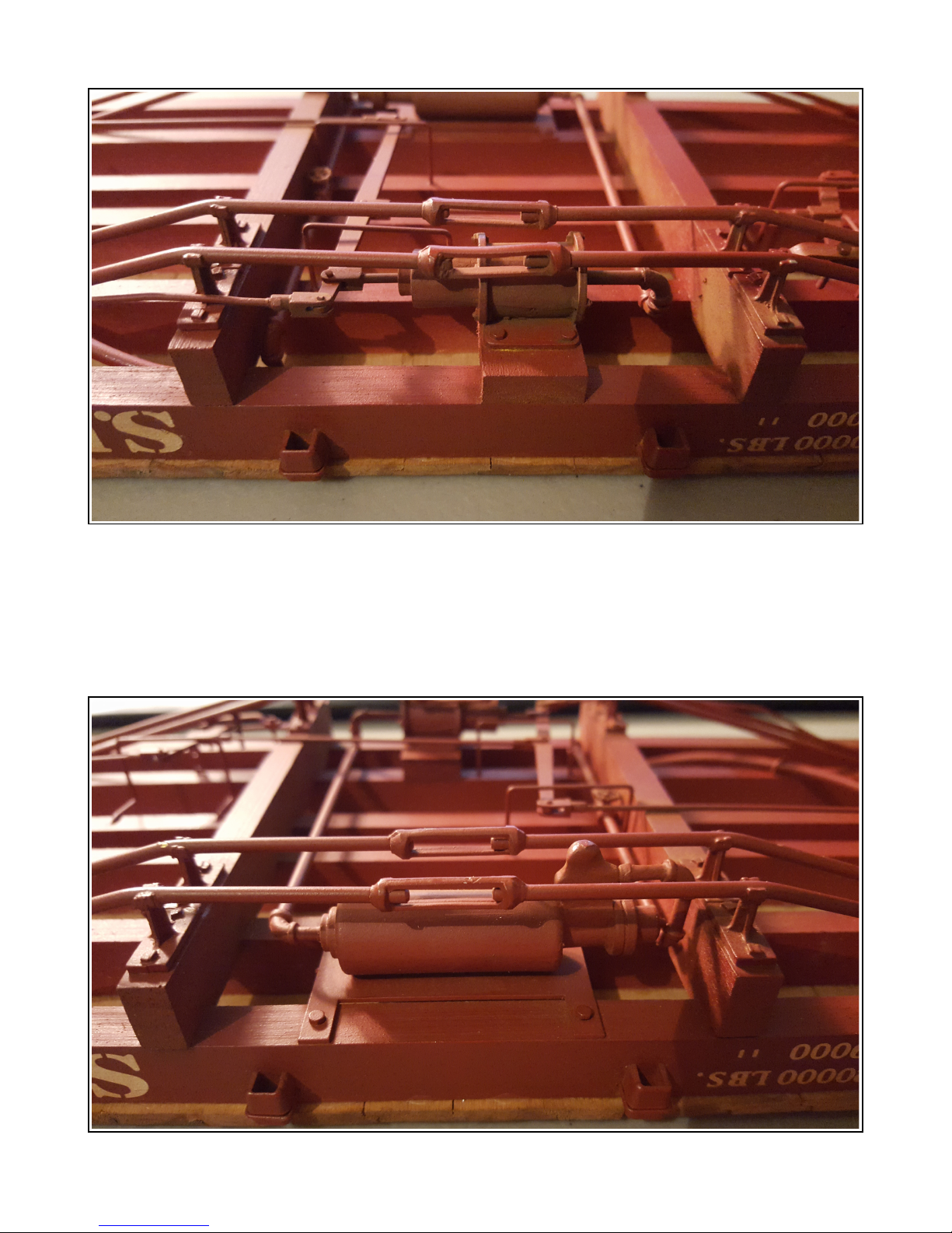
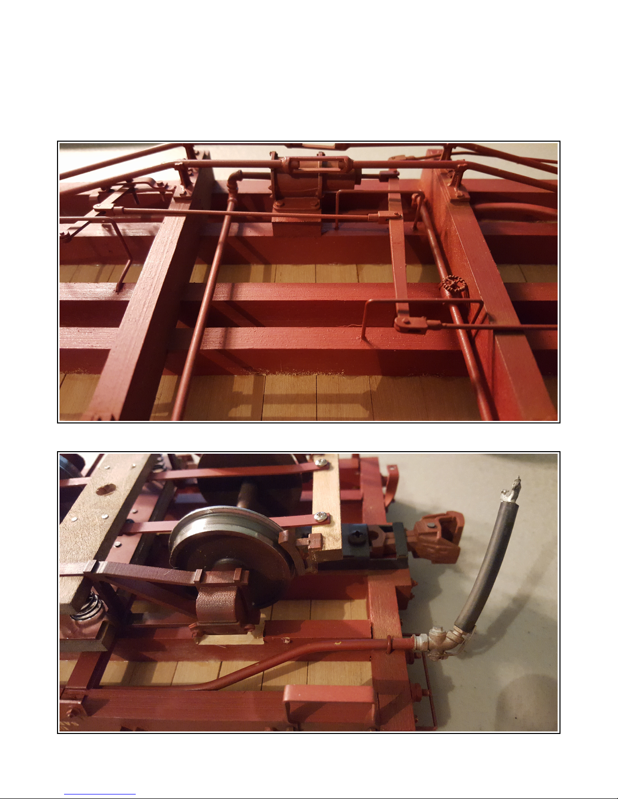
Table of contents
Other The Train Department Toy manuals

Popular Toy manuals by other brands

Hangar 9
Hangar 9 Taylorcraft 20cc ARF Assembly manual

Horizon Hobby
Horizon Hobby Viper 90mm EDF instruction manual

Mattel
Mattel Hot Wheels Disney Pixar Toy Story 3 Claw... instructions

Hasbro
Hasbro G.I.JOE WOLF HOUND quick start guide

Innoflight
Innoflight GALAXY 950 operating manual

Silverlit
Silverlit PicooZ Tandem Z-1 instruction manual


