flying Thinz Mad 3D Taco User manual

Mad 3D Taco
An All Out 3D Fun Fly Plane
The FlyingThingZ Mad 3D Taco is a fun 3D aerobatic park flyer’s dream. This is a high performance
electric R/C airplane designed for all out 3D aerobatics using inexpensive power systems such as the
GWS EPS350D motor/gearbox combos.
Utilizing space age materials such as depron and carbon fiber, simple construction methods, and
adding small but powerful electric drive systems, you'll get a spectacular performing electric R/C park
flyer airplane capable of performing 3D maneuvers previously only expected from much larger and
more expensive glow or gas models. Torque rolls with easy; knife edge and harrier right on the deck;
upright or inverted flat spins; If you can dream it up, the FlyingThingZ Mad3D Taco can do it.
All parts are laser cut with the utmost precision which makes assembly a snap. No special tools are
required for alignment, all the parts fall together effortlessly. The Mad 3D Taco could easily be assem-
bled within 3 to 5 hours.
Copyright © 2005Kit# FTZ3D003
Specifications
Wingspan: 37”
Weight: 14 to 16 oz
Radio: 4 Channel with Micro Servos
Motor: GWS 350D to HiMax 2025

2
Table of Contents
Warranty Information...................................................3
Warnings and Safety Precautions............................................. 3
Before Starting the Assembly Process........................................... 3
Using This Manual.................................................... 4
Kit Contents........................................................4
Required Tools and Adhesives...............................................4
Wing Assembly...................................................... 5
Preparing Control Surfaces................................................ 5
Elevator Assembly.....................................................5
Finalized Assembly.................................................... 6
Painting Tips....................................................... 6
Install Control Surfaces..................................................7
Radio & Control Preparation............................................... 8
Radio Installation.....................................................8
Finalize Radio Setup................................................... 10
Throws & Center of Gravity................................................10
Pre-Flight Checklist....................................................11
AMA Safety Code.....................................................11

3
Warranty Information
FlyingThingZ, Inc. guarantees this model to be free from defects in material and workmanship at the date of purchase. This warranty
does not cover any parts damaged by use or modifications. In no way shall FlyingThingZ, Inc. liability exceed the original cost of the
purchased model. Further, FlyingThingZ, Inc. reserves the right to modify this warranty without prior notice.
In that FlyingThingZ, Inc. has no control over the final stages of assembly or material used for the final assembly, no liability shall be
assumed nor accepted for any damage of the final user-assembled product. By the act of using the final product, the user accepts all
resulting liability.
We, as a kit manufacture, provide you with a top quality kit and manual, but the quality and flying characteristics of your finished
model depend on how you build it; therefore, we cannot in any way guarantee the performance of your completed model and no rep-
resentations are expressed or implied as to the performance or safety of your completed model.
If the buyer is not prepared to accept the liability associated with the use of this product, the buyer is advised to return this kit
immediately, in new and unused condition, to the place of purchase.
Warnings and Safety Precautions
READ THROUGH THIS MANUAL BEFORE STARTING ASSEMBLY. IT CONTAINS IMPORTANT WARNINGS AND
INSTRUCTIONS CONCERNING THE ASSEMBLY AND USE OF THIS MODEL.
AN RC AIRCRAFT IS NOT A TOY! IF MISUSED, IT CAN CAUSE SERIOUS BODILY HARM AND DAMAGE TO PROPERTY.
FLY ONLY IN OPEN AREAS, PREFERABLY AT AMA (www.modelaviation.com) APPROVED SITES. FOLLOW ALL INSTRUC-
TIONS INCLUDED WITH YOUR RADIO AND ENGINE.
You must assemble the model according to the instructions. Do not alter or modify the model, as doing so may result in an
unsafe or unstable aircraft. In a few cases the instructions may differ slightly from the images provided. In these cases, the written
instructions should take precedence.
Take your time to build straight, true and strong.
You must use an R/C radio system that is specifically designed for aircraft frequencies, properly tuned and in first class working
condition. The correctly sized engine displacements and miscellaneous components should be used throughout the building process
as specified on this manual.
Check the operation of your model before each flight and insure that all equipment is fully operational and all hardware is secure.
Be sure to check all linkage connections and parts that may become dislodged during flight.
This kit is not intended as a trainer. If you are not an experienced pilot, you should fly the model only with the help and supervi-
sion of a competent, experienced R/C pilot.
Before Starting the Assembly Process
Before beginning assembly of the Mad 3D Taco, remove all parts from their packages for inspection. Inspect all hardware, fuselage
parts, wing components and foam for damage. If you find any damaged or missing parts, please contact us directly.
FlyingThingZ, Inc.
34 Chatham Hill Road
Stroudsburg, PA 18360
www.flyingthingz.com
4
Using This Manual
This manual is divided into sections to aid in the assembly process. It provides an easier more concise layout allowing for breaks
between each major section. Additionally, check boxes have been provided next to each step to help keep track of the completed
assembly process. Steps with two check boxes indicate that the step is repeated, such as for a right and left wing panel, control link-
ages or fuselage side. Remember to take your time and follow the directions carefully.
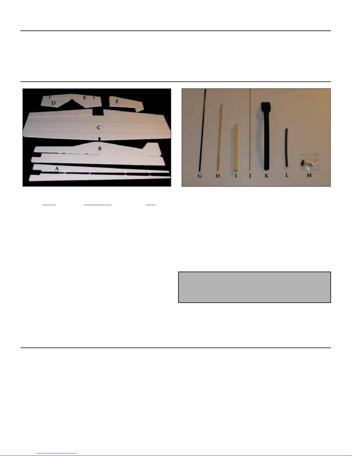
Kit Contents
Part # Description Qty.
AHorizontal Fuse 2
BVertical Fuse 1
CWing 1
DElevator 2
EHorizontal Stab 1
FRudder 1
GCarbon Fiber Rod 4
HSkid Plate 1
IMotor Mount 1
JControl Rod Wire 1
KVelcro Strap 1
LHeat Shrink Tubing 1
MEZ Connector 4
Not Shown Elevator Joiner 1
Required to Complete Kit
4 Channel Radio with 4 Micro Servos (eg. Hitech HS-55)
Electric Motor (GWS 350D, HiMax 2015 or 2025)
Speed Controller (eg. Phoenix 25)
Battery Pack (7.4v or 11.1v Li-Po or NiMH)
Gear Box
Propeller
Avoid Using CA to bond parts on foam. Regular CA will eat
the foam and ruin it. FlyingThingZ recommends epoxy, foam
safe CA or Gorilla Glue
5 or 30 Minute Epoxy
#120 Sand Paper
Sanding Block
Hobby Knife
Pen or Pencil
Assorted Screw Drivers
Building T-Pins
Razor Saw
Wire Cutters
Needle Nose Pliers
Paper Towels
Ruler
Mixing Sticks
Alcohol
Rotary Tool / Dremel
Router Attachment
Hot Glue Gun
Hinges or Hinge Tape
Drill
1/16” Drill Bit
Double Sided Tape
Double Sided Velcro Tape
Paint
Foam Safe CA or Gorilla Glue
Required Tools and Adhesives
5
Wing Assembly
Glue the two carbon fiber rods into the precut slots on the
back of the wing. Make sure to lay the wing on a flat level sur-
face before allowing the glue to set. Wipe off any excess glue
with alcohol and paper towels.
Install the wing into the vertical fuselage. Use t-pins and the
provided squares to attach the wing to the fuselage. Run a bead of
glue alone the top and bottom edges of the wing. Quickly move to
the next step before the glue sets.
Insert the motor mount into it’s slot in the fuselage and into
the notch on the wing. Glue it in place making sure that motor
mount is centered with the fuselage. The motor mount should
help straighten the wing.
Put the Taco aside as the glue sets and move on to the next steps.
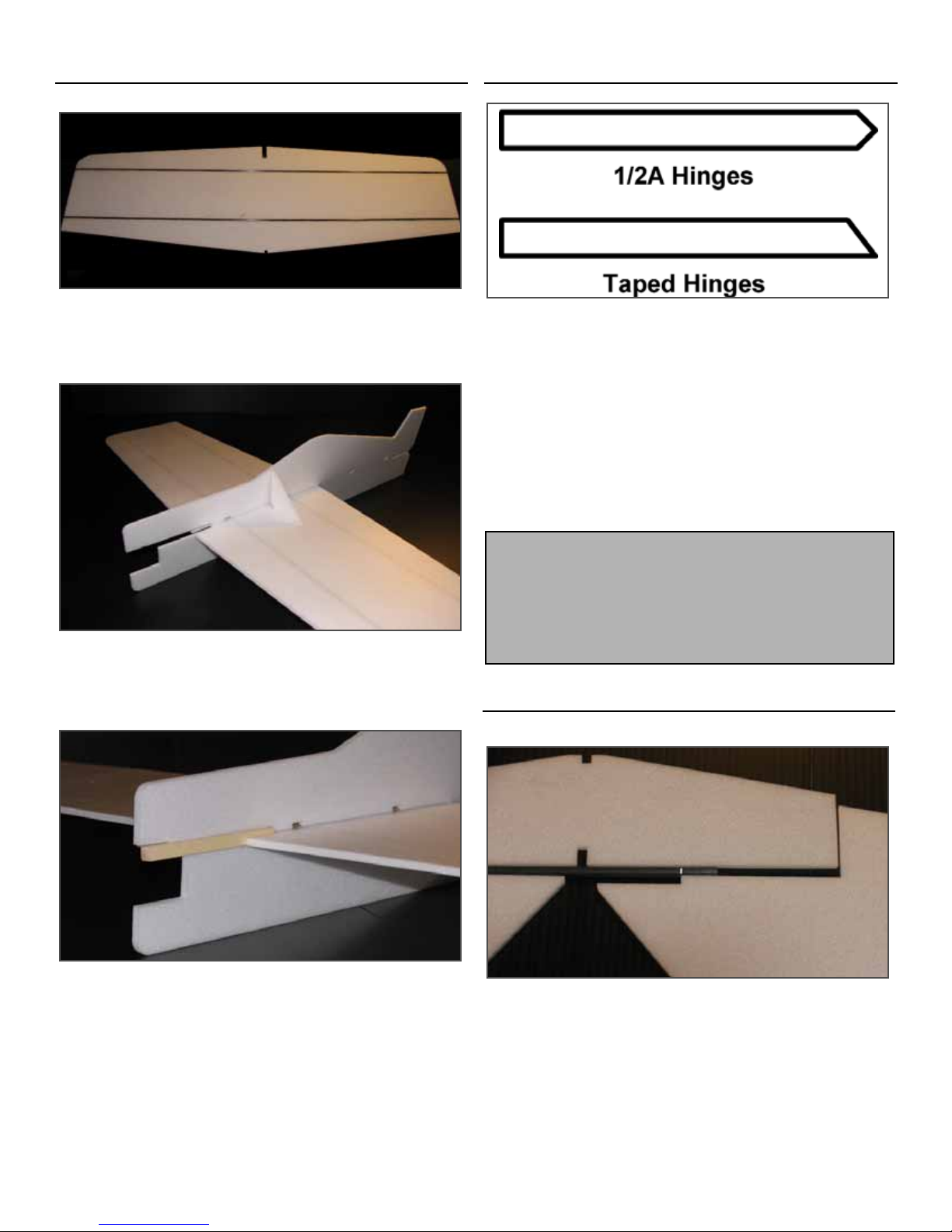
Preparing Control Surfaces
To prepare the control surfaces, you have to make a decision. If
you are going to hinge your control surfaces with regular hinges,
then the surface must be shaped as shown above for the 1/2A
Hinges.
If you prefer to use tape to hinge your control surfaces, then the
surfaces must be shaped as shown above for Taped Hinges.
Using #120 grit sandpaper on a sanding block, shape the edges
of your control surfaces as shown above for your preferred hing-
ing method. Make sure the correct edge on the control surface is
shaped by checking them against the wing or stab.
Elevator Assembly
Dry fit the elevators onto the horizontal stab with the elevator
joiner between the two elevator halves. Make a mark on the
elevator joiner where it meets the second elevator. Cut the eleva-
tor joiner on the mark. Make sure to compensate for the outside
edges of the elevator that butt up against the horizontal stab.
FlyingThingZ recommends taking the extra time and steps to
hinge your control surfaces with Dubro 1/2A Hinges (part# 118
or 119)
If you’d prefer to use the tape method, we recommend using
Dubro’s Electric Flyer Hinge Tape (part#916)

6
Test fit the elevators with the joiner installed. Sand down the
joiner as necessary to get a good fit. Make sure the elevators are
not rubbing against the stab.
Using your preferred gluing method, join the two elevator
halves with the elevator joiner in place. Make sure to lay them on
a flat surface to assure they are perfectly level.
Put the elevator assembly aside as the glue sets and move on to the
next steps.
Finalized Assembly
Slide the horizontal stab through the back of the Taco. The fit
is extremely tight so be careful when inserting it. Once inserted,
make sure that the stab is fully seated in position before gluing.
Use the provided squares with t-pins to hold the assembly in place
as the glue sets.
Dry fit the horizontal fuselage on top of the wing. From the
bottom of the Taco, make a mark onto the horizontal fuselage
where the wing’s leading edge and trailing edge meet. Do the
same for the horizontal stab. This is to assure you don’t put glue
outside the wing area. Apply a liberal amount of glue to the hor-
izontal stab between your marks and glue into place. Use t-pins
to hold the assembly together as the glue sets.
Glue the skid plate onto the Taco’s belly. Once the glue has set,
the Mad 3D Taco is ready to be painted.
Painting Tips
It’s finally time to paint your Mad 3D Taco.
Before painting the model, make sure it it free of dust and oil. Use
alcohol and a lint free rag to rub off any oils or dust on the model.
Alternatively, you can use a tack cloth to remove dust.
FlyingThingZ recommends standard spray paint that can be
picked up at most hardware stores. There is one thing that you
should avoid when using spray paints. Make sure it does not con-
tain any rust inhibitors. Rust-O-leum and other paints with these
inhibitors will deteriorate the foam.
When applying the paint, use multiple light coats. Painting it on
too thick will add weight and create runs. Use the foam triangles
to test your paint before applying it on the Taco.
Other painting methods you can use are:
Permanent Colored Magic Markers
Latex Based Paint
Acrylic Based Paint
Airbrushing

7
Install Control Surfaces
1/2A Hinges
Use a hinge as a guide to mark both the wing and the aileron
where the hinge locations will be. The wing half should have 4
hinges evenly spaced apart from each other.
Repeat this step for the rudder and elevators. The rudder uses
3 hinges and the elevator uses 2 hinges per side.
Using a hinge slotting tool, make a slit in the foam at the
locations marked in the previous step. With a small amount of
glue, install the hinges into the wing. If a hinge tool is not avail-
able, use your best judgement for centering the slits where the
hinges will install.
Repeat this step for the rudder and elevators.
Install the aileron using a small amount of epoxy. Move the
ailerons up and down so that the hinge pins don’t get stuck.
Finally, repeat the same process for the rudder and elevator.
Keep moving the control surfaces to assure they don’t get stuck.
Tape Hinges (Optional Method)
Optional: Apply the first strip of tape to the wing or stab. Place
the control surface at the angle that was created on the control sur-
face and attach tape to the control surface.
Optional: Move the control surface to the opposite side and add
an additional strip of tape to the other side.
Optional: The finished taped hinge control surface.
Tip: Applying a small amount of vaseline or oil to the hinge
pin will help prevent it from getting gummed up with glue.
8
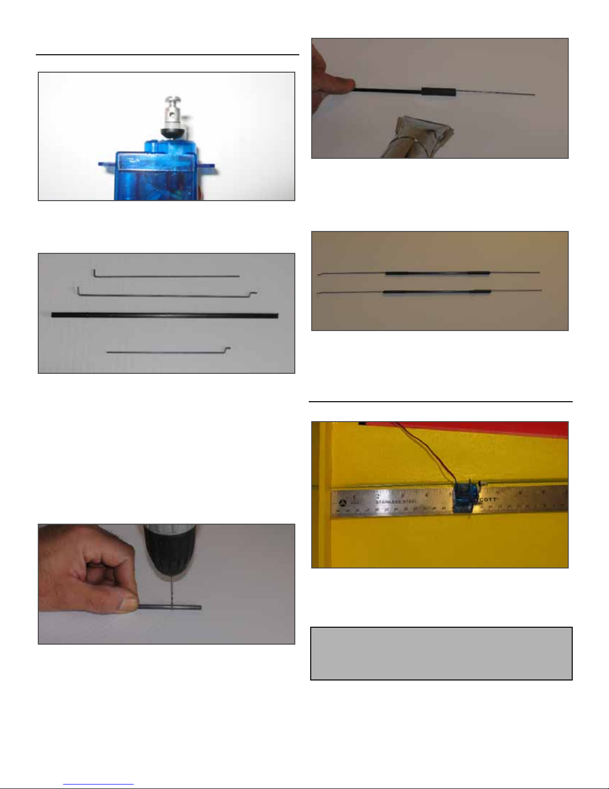
Radio & Control Preparation
Attach the control horns to your servos and attach the
included Mini EZ Connectors to the outer most hold on the control
horn as shown above.
Cut down the carbon fiber rods to 8”.
Create two wires with a 90 degree bend at 5 1/2”. The wire
should run 5 1/2” then turn 90 degrees. Make sure the bend is no
more than a 1/4” long.
Create two wires with a 90 degree bend and a Z bend on the
other side that is 4 1/2”. The length of the wire before any bend
should be 4 1/2”.
Finally create two wires with a Z bend bend at 4”. The wire
should run 4” then turn into a Z bend.
Drill a 1/16” hole, 1” from each end of the carbon rod. Make
sure the holes line up as much as possible with each other.
Cut down the heat shrink tubing to 1 1/2” pieces. Place
the tubing over the carbon fiber rod and insert the 90 degree bend
into the drilled hole. Using a hot air gun or lighter, heat the tub-
ing until it wraps tightly around the rod and wire. Add a few
drops of CA into the opening of the rod for added strength.
One side should use the wire that has the Z bend, while the other
end, should just have the straight wire as shown in the image
above.
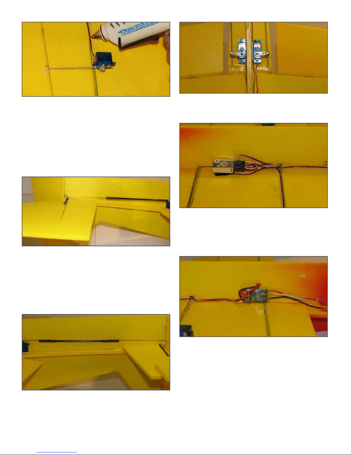
Radio Installation
Install the aileron servos on the bottom of the wing 5” from
the side of the fuselage. Use double sided tape or hot glue to hold
the servo in place. Repeat on the other side. Make sure to clean
all surfaces with alcohol before applying your double sided tape.
Tip: FlyingThingZ recommends using double sided tape over
hot glue. During extremely hot days, we have experience ser-
vos coming loose during flight.
9
Attach the aileron control rod wire through the control horn.
You may have to use a drill bit or X-acto knife to make the hole a
little bigger for the rod. Slip the wire through the hole in the EZ
connector and punch the control horn into the foam on the aileron.
Make sure the holes on the control horn are as close to the center
of the wing / aileron joint as possible.
Glue the horns in place. Add a small dot of glue on the
opposite side that protrudes from the control horn.
Use a few beads of hot glue to hold the wire in place.
Attach a control horn to one of the assembled carbon fiber rod
control arms. Run the other end through the EZ Connector on the
elevator servo. Line up the rod with the vertical fuselage and
punch the control horn through the foam as close to the joint
between the stab and elevators.
Glue the horns in place and place a small dot of glue on the
opposite side that protrudes from the control horn. Do not attach
the servo at this time.
Install the rudder control horn in the same manner as previ-
ous steps.
The elevator and the rudder servos should be lined up as
shown above. Use double sided tape or hot glue to hold the ser-
vos in place. Use beads of hot glue to hold the wires in place.
Install the receiver as far forward as the shortest servo wire
will allow. You’ll have to make a hole in the vertical fuselage to
pass the wires from the other side to the receiver. When you route
your receiver antenna, try to keep it away from your servo leads.
Use double sided velcro tape to hold the receiver in place. Use
beads of hot glue to hold the wires in place.
Install your speed controller on the opposite side of the receiv-
er. Pass the wire to the receiver through the hold crated to pass the
servo leads through. Create another hold above the speed con-
troller to pass the battery connector through. Attach the speed
controller to the model with double sided velcro tape. Use beads
of hot glue to hold the wires in place.
10
Mount the battery onto the vertical fuselage centered with the
leading edge of the wing. Cut slits on the top and bottom of the
battery location to pass the provided velcro strap through. Make
sure the battery leads can plug into the speed controller.
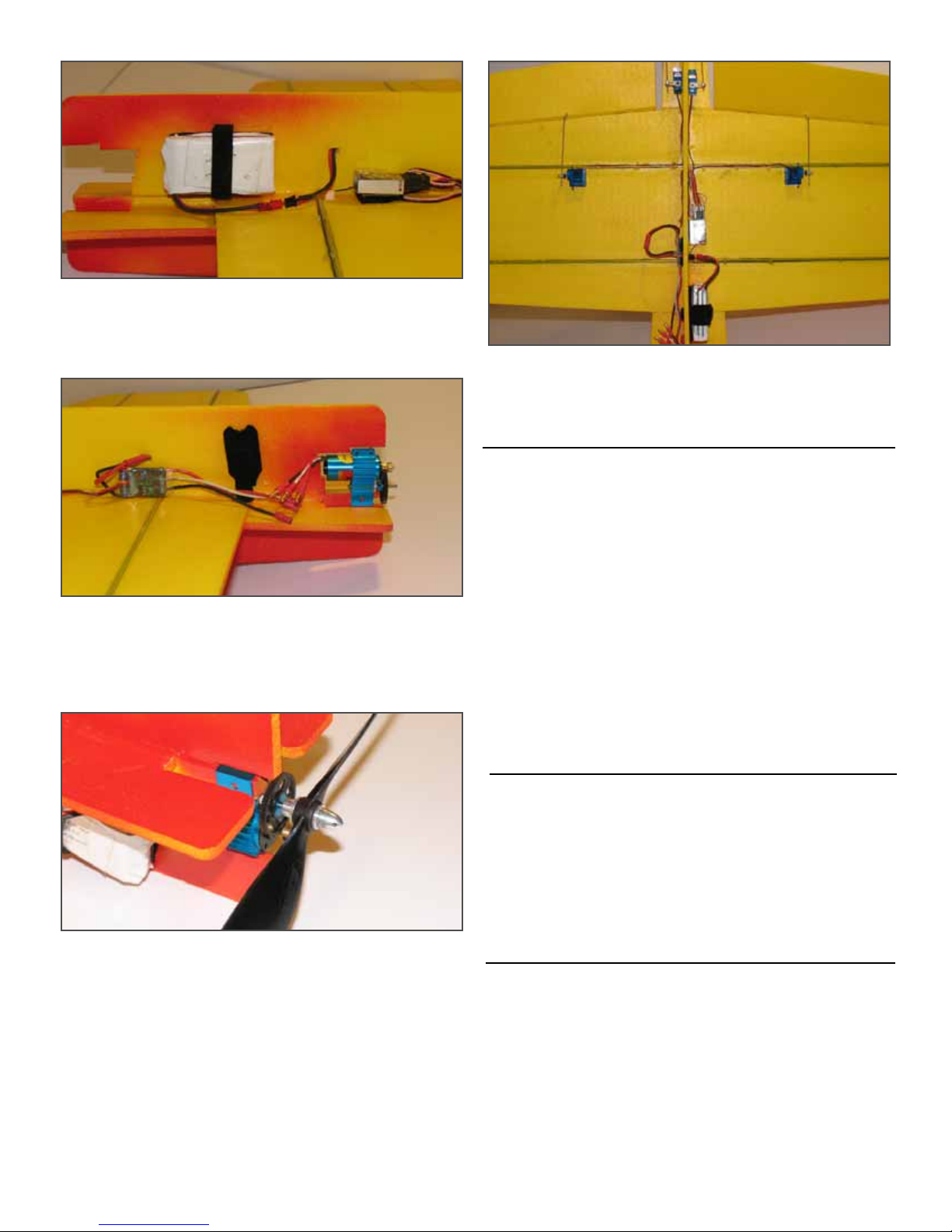
Install the motor and gearbox onto the motor mount. Using a
1/16” drill bit, make a hole to secure the gearbox to the motor
mount. Use a servo mounting screw to secure the gearbox to the
motor mount. DO NOT connect your motor wires to the wires on
the speed controller at this time.
Securely install the propeller onto the gearbox output shaft.
Follow the manufacturers recommendations for securing the prop
and prop nut to the shaft.
The final setup should ultimately look similar to the image above.
Make sure to secure your wires with hot glue or your preferred
method.
Finalize Radio Setup
Turn on your transmitter and connect the battery to the speed
controller. Center all servos using the transmitters trim or sub-
trim. Make any necessary adjustments on the EZ Connectors and
control rods to assure your control surfaces are perfectly lined up.
Make sure all the control surfaces operate in the proper direc-
tion for your control input.
Follow the manufactures instructions on setting up the speed
controller and motor/gearbox combination you have chosen for
your plane.
Attach the motor wires to the speed controller. Make sure
your throttle operates in the proper direction. Be extremely care-
ful with the prop when connecting the battery for the first time.
Throws & Center of Gravity
The throws should be set as high as possible on all control sur-
faces. Set a 50% dual rate on one switch as a bailout if you feel
the controls are too sensitive.
The CG should be 5 1/4” from the leading edge. Adjust the bat-
tery position to obtain a balancing point on or as close to the
location of the center of gravity.
Damage Repair
Repairing a damaged aircraft is easy and very quick. Usually,
you can be up and flying again within minutes of a severe crash.
Use 5 minute epoxy or hot glue to join any broken parts. Make
sure not to melt the foam with the hot glue gun.
If you bend your drive shaft, try straightening it out before
replacing it. We’ve bent a few shaft and have been able to bend
them back close enough to avoid vibrations.

11
Pre-Flight Checklist
Check the CG according to the steps outlined in the balanc-
ing section of this manual
Make sure that battery and receiver are securely mounted.
Make sure your receiver antenna is fully extended. Do not
cut any excess antenna wire.
Use a threadlocking compound on all metal to metal
fasteners such as nuts, bolts and set screws.
Make sure all hinges are secure and in good working
condition.
Reinforce holes for wood screws with CA where
appropriate.
Confirm all controls operate freely and in the correct direc-
tion. Make sure all throws are set as specified in this manual.
Make sure all your wire connections are secure and in good
physical condition.
Make sure the prop nut is fully fastened and secure.
Place your name, address AMA number and telephone
number on or inside your model.
Cycle all battery packs and make sure they are fully charged
before flying.
Range check your radio at the flying field before the first
flight following the radio manufacturer's instructions.
GENERAL
1. A model aircraft shall be defined as a non-human-carrying
device capable of sustained flight in the atmosphere. It shall not
exceed limitations established in this code and is intended to be
used exclusively for recreational or competition activity.
2. The maximum takeoff weight of a model aircraft, including
fuel, is 55 pounds, except for those flown under the AMA
Experimental Aircraft Rules.
3. I will abide by this Safety Code and all rules established for the
flying site I use. I will not willfully fly my model aircraft in a
reckless and/or dangerous manner.
4. I will not fly my model aircraft in sanctioned events, air shows,
or model demonstrations until it has been proven airworthy.
5. I will not fly my model aircraft higher than approximately 400
feet above ground level, when within three (3) miles of an airport
without notifying the airport operator. I will yield the right-of-
way and avoid flying in the proximity of full-scale aircraft, utiliz-
ing a spotter when appropriate.
6. I will not fly my model aircraft unless it is identified with my
name and address, or AMA number, inside or affixed to the out-
side of the model aircraft. This does not apply to model aircraft
flown indoors.
7. I will not operate model aircraft with metal-blade propellers or
with gaseous boosts (other than air), nor will I operate model air-
craft with fuels containing tetranitromethane or hydrazine.
8. I will not operate model aircraft carrying pyrotechnic devices
which explode, burn, or propel a projectile of any kind.
Exceptions include Free Flight fuses or devices that burn produc-
ing smoke and are securely attached to the model aircraft during
flight. Rocket motors up to a G-series size may be used, provided
they remain firmly attached to the model aircraft during flight.
Model rockets may be flown in accordance with the National
Model Rocketry Safety Code; however, they may not be launched
from model aircraft. Officially designated AMA Air Show Teams
(AST) are authorized to use devices and practices as defined
within the Air Show Advisory Committee Document.
9. I will not operate my model aircraft while under the influence
of alcohol or within eight (8) hours of having consumed alcohol.
10. I will not operate my model aircraft while using any drug
which could adversely affect my ability to safely control my
model aircraft.
11. Children under six (6) years old are only allowed on a flight-
line or in a flight area as a pilot or while under flight instruction.
12. When and where required by rules, helmets must be properly
worn and fastened. They must be OSHA, DOT, ANSI, SNELL or
NOCSAE approved or comply with comparable standards.
RADIO CONTROL
1. I will have completed a successful radio equipment ground-
range check before the first flight of a new or repaired model
aircraft.
2. I will not fly my model aircraft in the presence of spectators
until I become a proficient flier, unless I am assisted by an experi-
enced pilot.
3. At all flying sites a straight or curved flightline must be estab-
lished, in front of which all flying takes place. Only personnel
associated with flying the model aircraft are allowed at or in
front of the flightline. In the case of airshows, demonstrations, or
competitions, straight lines must be established. An area away
from the flightline must be maintained for spectators. Intentional
flying behind the flightline is prohibited.
4. I will operate my model aircraft using only radio-control fre-
quencies currently allowed by the Federal Communications
Commission (FCC). Only individuals properly licensed by the
FCC are authorized to operate equipment on Amateur Band fre-
quencies.
5. I will not knowingly operate my model aircraft within three (3)
2005 Official AMA National Model Aircraft Safety Code
Effective January 1, 2005

12
miles of any preexisting flying site without a frequency-manage-
ment agreement. A frequency-management agreement may be an
allocation of frequencies for each site, a day-use agreement
between sites, or testing which determines that no interference
exists. A frequency-management agreement may exist between
two or more AMA chartered clubs, AMA clubs and individual
AMA members, or individual AMA members. Frequency-man-
agement agreements, including an interference test report if the
agreement indicates no interference exists, will be signed by all
parties and copies provided to AMA Headquarters.
6. With the exception of events flown under official AMA
Competition Regulations rules, after launch, no powered model
may be flown outdoors closer than 25 feet to any individual,
except for the pilots and helpers located at the flightline.
7. Under no circumstances may a pilot or other person touch a
model aircraft in flight while it is still under power, except to
divert it from striking an individual.
8. Radio-controlled night flying is limited to low-performance
model aircraft (less than 100 mph). The model aircraft must be
equipped with a lighting system which clearly defines the air-
craft's attitude and direction at all times.
9. The operator of a radio-controlled model aircraft shall control
it during the entire flight, maintaining visual contact without
enhancement other than by corrective lenses that are prescribed
for the pilot. No model aircraft shall be equipped with devices
which allow it to be flown to a selected location which is beyond
the visual range of the pilot.
FREE FLIGHT
1. I will not launch my model aircraft unless I am at least 100 feet
downwind of spectators and automobile parking.
2. I will not fly my model aircraft unless the launch area is clear
of all individuals except my mechanic, officials, and other flyers.
3. I will use an effective device to extinguish any fuse on the
model aircraft after the fuse has completed its function.
CONTROL LINE
1. I will subject my complete control system (including the safety
thong where applicable) to an inspection and pull test prior to
flying. The pull test will be in accordance with the current
Competition Regulations for the applicable model aircraft catego-
ry. Model aircraft not fitting a specific category shall use those
pull-test requirements as indicated for Control Line Precision
Aerobatics.
2. I will ensure that my flying area is clear of all utility wires or
poles and I will not fly a model aircraft closer than 50 feet to any
above-ground electric utility lines.
3. I will ensure that my flying area is clear of all nonessential par-
ticipants and spectators before permitting my engine to be
started.
SPECIALIZED SUPPLEMENTAL SAFETY CODES
Specialized supplemental Safety Codes exist for the following:
RADIO CONTROL COMBAT (#525)
GENERAL RADIO CONTROL RACING (#530)
GIANT SCALE RADIO CONTROL RACING (#515-A)
GAS TURBINE OPERATION (Note: Special waiver required)
(#510-A)
These special codes and appropriate documents may be obtained
either from the AMA Web site or by contacting AMA
Headquarters.

13
Unique and Exotic Aircraft from FlyingThingZ
Indy Sport Car M1A1 Flying Tank
Flagship .40 Extra 300 3D
Sky Cutter .40 V2 Witch Wilga

Table of contents
Popular Toy manuals by other brands


Fisher-Price
Fisher-Price BGC55 instructions

ATOMIC MASS GAMES
ATOMIC MASS GAMES STAR WARS LEGION SWL11 Assembly

MTHTrains
MTHTrains RAIL KING SOUTHERN Ps-4 4-6-2 DIE-CAST STEAM... operating instructions

Tomy
Tomy Starlight Dreamshow Instructions for use

HPI Racing
HPI Racing Sprint 2 sport instruction manual

YIBOO
YIBOO Dragon 807 UJ807 user manual