FM Systems PG-1 User manual
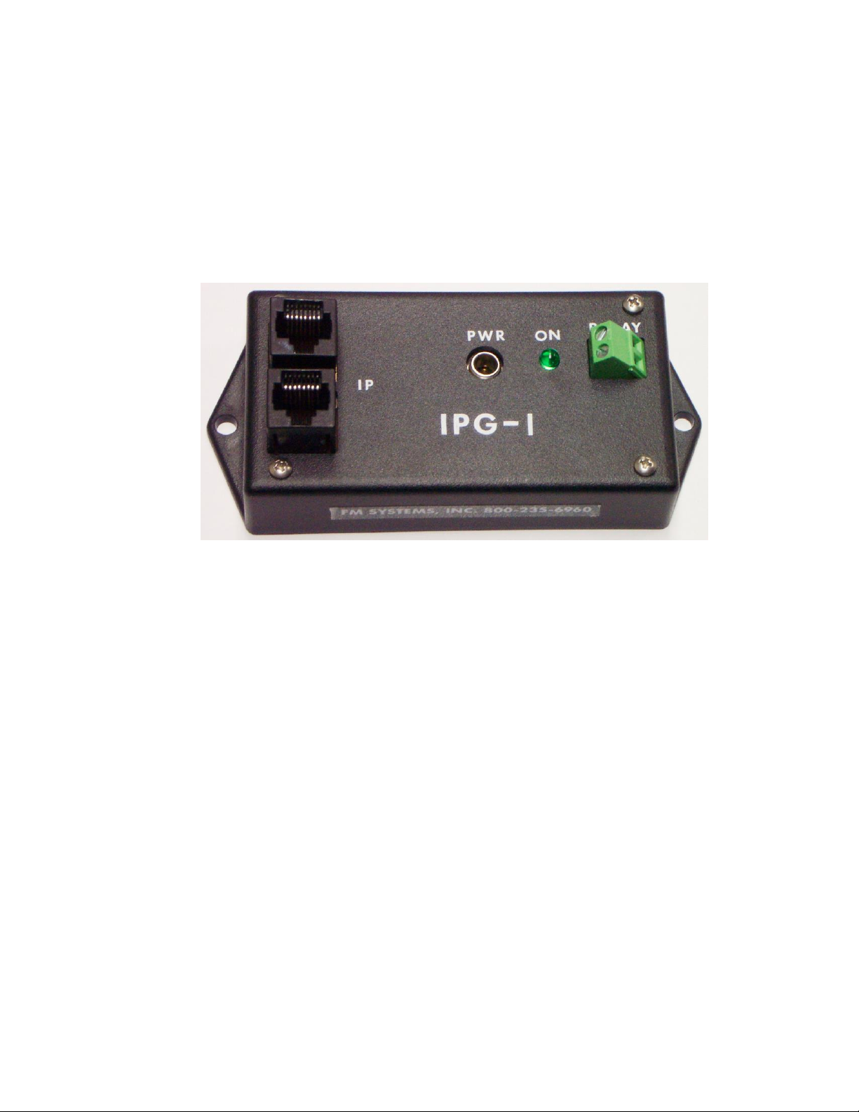
IPG-1
IP CAMERA-GUARD
INSTRUCTION BOOK
IB6444-01

TABLE OF CONTENTS
DESCRIPTION 2
MOUNTING INSTRUCTIONS 2
HOW TO CABLE THE IPG-1 3
POWER SUPPLY INSTALLATION 3
OPERATION 3
CARE AND MAINTENANCE 3
APPLICATIONS (WHERE TO USE THE SYSTEM) 3
GROUND LOOPS THAT CAUSE INTERMITTANT DATA 3
PROGRAMMING THE RELAY OUTPUT 4
TROUBLE SHOOTING THE DATA SIGNAL 5
IPG-4.ISB PAGE 1 OF 5

DESCRIPTION
The IPG-1 Camera Guard monitors the communication path of IP camera data signals.
This supervisory system will identify the loss of any video data signal due to removal of the
camera, loss of power to the camera, a camera cable disconnect, or a defective camera output.
The IPG-1 continuously displays the "Data on" condition of one IP camera with an L.E.D.
indicator for the camera channel and relay contact output for external alarms. Use it to monitor
your IP cameras and shut down un-attended gas pumps if the IP camera is tampered with.
A normally Open or Normally Closed Alarm contact is provided to send an alarm or
activate equipment when loss of data occurs. This contact is field programmable for Normally
Open or Normally Closed contact operation. Connect this unit to a local alarm panel to alert
monitor personnel that a camera is being tampered with or send a message to a remote site by
connecting the alarm output to external dialing equipment. It can be used to shut down
equipment such as gas pumps when the IP video fails.
The IPG-1 will identify tampering or failure of cameras when it occurs, reducing the
liability associated with extended and undetected loss of area security when cameras are
rendered inoperative without notification. The IPG-1 increases the level of security provided by
the IP video camera.
The IPG-1 Camera Guard can be connected anywhere between the camera and the
Monitor equipment in the IP video data path. You can connect it near the IP camera to activate a
local alarm or at the monitor location to alert guard personal and automatically shut down
equipment. The "High Impedance Loop through Input" will not affect the data or picture quality of
the video signal even if the power fails. The unit detects the loss of data communication between
the IP camera and the monitor location for any reason such as power loss at the camera or
camera failure, broken, shorted or disconnected wire cables and tampering of any kind.
Use this unit in any IP video installation that requires guaranteed continuous video
monitoring. Use the IPG-1 to monitor the camera in sensitive areas like loading docks or any
area subject to the unauthorized movement of product or stock. Or use it to determine if you
have an intermittent failure problem in any IP video system. The IPG-1 has an easy mounting
flange that will mount to any surface with just two screws and is supplied with a 24 VDC power
cube.
MOUNTING INSTRUCTIONS
The rugged one piece mounting structure allows you to mount the unit firmly in place with
two screws. Select a place to mount the unit away from harsh or wet environments indoors is
recommended. The IPG-4 should be located near the monitor equipment or anywhere along the
path of the IP video signal. Select a position that gives you the best access to cable the system
and reduce the labor in installation.
HOW TO CABLE THE IPG-1
Attach the cable coming from the camera to one of the IP Video 8P8C (RJ-45)
connectors. The connector pair loops through so you can use either one for the input or output.
Then attach a cable from the other IP Video 8P8C (RJ-45) connector to the monitor equipment.
IPG-1ISB PAGE 2 OF 5

POWER SUPPLY INSTALLATION
The IPG-1 is powered by a 24 VDC wall mount power transformer. Just plug the 24 VDC
connector into the jack marked "24VDC PWR". The Green LED will not illuminate until both the
power supply and the video data is applied.
OPERATION
When IP video is applied to the IPG-1 it takes a continuous sample of the camera signal
and monitors the data level. When correct IP data levels are detected the unit displays a green
LED “ON” and the alarm relay is energized. The alarm output is field selectable with jumper J2
on the PC card for normally open (NO) or normally closed (NC) contact operation. A separate
set of jumpers J3 select Relay Contact output or Low Voltage Supply output. When the Low
Voltage Supply is selected, the low voltage supply appears at the relay output terminals under
the control of the Normally Open or Normally Closed relay jumpers.
If the IP Video level drops below operational limits a relay will de-energize to operate the
alarm contacts and the LED will be off indicating a loss of data from the camera.
If the NVR "Network Video Recorder" fails to communicate with the camera the camera
will stop transmitting video and go into a polling mode. This failure of the NVR will be detected by
camera polling signals and the unit will output an alarm condition on the relay but the LED will
slowly flash on and off indicating a loss of data communication from the NVR.
CARE AND MAINTENANCE
There is no routine maintenance or calibration required with this equipment.
APPLICATIONS (WHERE TO USE THE SYSTEM)
This system can be used anywhere that an IP video signal on cable exists. It can be used
near the camera to operate a local alarm or at the monitor site for integration into the existing
alarm system. It can be used with access control to prevent access to areas unless video is
operational to guaranty that users are video taped entering the monitored area.
GROUND LOOPS THAT CAUSE INTERMITTANT DATA
The IPG-1 is completely isolated from ground to prevent ground loops from occurring due
to installation of the Camera Guard. Each camera connection is also isolated from each other to
prevent ground loop creation. The IPG-1 will not induce ground loops in the data signal.
PROGRAMMING THE RELAY OUTPUT
The relay output can be programmed in the field using the jumper jacks on the PC board.
The units are shipped from the factory programmed for (NO) Normally Open contacts. If (NC)
Normally Closed contacts are desired follow the steps below.
1. Remove the four black screws in the outer most corners of the bottom lid of the product
enclosure. These are the recess flat-head screws. DO NOT REMOVE THE PAN HEAD
SCREW THAT ARE AT THE INSIDE EDGE OF THE BOX ON THE TOP SIDE.
IPG-1ISB PAGE 3 OF 5
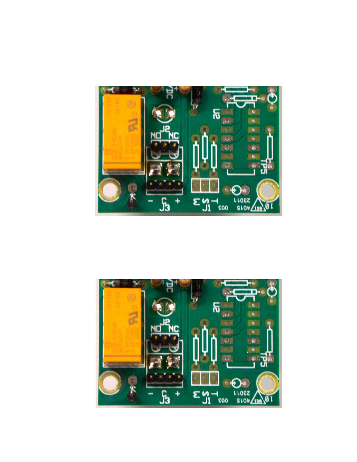
2. For contact relay output locate the black jumper jack on J2, next to the relay on the top of
the PC Board. There are three gold pins under the jumper jack. Select (NO) for Normally
Open or (NC) for Normally Closed and place the jumper jack on two of the three pins. The
top of the PC Board is marked with graphic to make programming easy. Note for relay
contact outputs the J2 jumper must be in the “C” position and only one shunt on the
middle two pins only.
3. For Low Voltage output operation position one shunt onto J3 connecting the outermost
two pins at the (+) mark and another shunt onto J3 at the other outermost two pins at the
(-) mark. There should be two jumper shunts on this jack for supply voltage output. Then
choose normally ON or normally OFF operation for the low voltage output and J2. For low
voltage supply output this unit is available in two versions. The 12 Volt version IPG-4/12
and the standard 24 Volt version IPG-1.
4. Replace the cover and the four black screws in the outer most corners of the enclosure.
IPG-1ISB PAGE 4 OF 5

TROUBLE SHOOTING THE DATA SIGNAL
The IPG-1 IP Camera Guard monitors the data flow from camera to the NVR and any
switches that might be in the system. The unit detects the loss of data transmission and
operates a relay to control pumps and other equipment. This unit will work best when the IP
video data is operating at full frame video, or high frame rate setting on the camera.
Features like built-in IP camera motion detection that only sends data when motion is
detected by the camera should be avoided as they radically reduce the amount of consistent
data flow and can cause a video loss detection to occur. Frame rates of 30 frames per second is
suggested with data rates set on low settings to even out the data flow. The purpose of these
setting is to provide as continuous a flow of data as possible. The IPG-1 is monitoring the
amount of data, so if the camera data is sent in quick bursts at high data rates and has long
periods of no data transmission in between the unit will consider that a loss of data transmission
and operate the relays accordingly. If the unit is placed after a data compressing switch or
repeater that causes the data flow to be compressed with long gaps in the data transmission this
can cause the unit to detect the long gaps in data flow as a failure of the video.
An indication of low data transmission can be determined by examination of the Green
LED lights on the IPG-1 unit. If the data rate is too low or un-even you may observe these LED
lights flickering or very dim and the relays could be turning on and off. This is a visible indication
of low data traffic and the frame rate on the camera should be selected to a high rate. Check to
see if the camera has any feature like built-in motion detection and turn it off in the camera. If
you suspect that a data switch or repeater is compressing the data by raising the data rate and
sending it at a higher Bit per second rate then temporarily move the unit to the input to the switch
and see of you get the same results. If the unit operates normally ahead of the switch, then the
switch should be replaced with one that does not re-configure the data flow.
If motion detection is needed to extend record time, do the motion detection and
reduction at the NVR in the recording setting and not in the camera itself. The IPG-1 uses the
data traffic of or amount of data sent by the camera to detect a loss of data so any equipment
that diminishes that data flow can affect how the unit operates the relays. Set the camera setting
for the best continuous flow of data possible for the best Camera Guard operation.
IPG-1ISB PAGE 5 OF 5
This manual suits for next models
1
Table of contents


