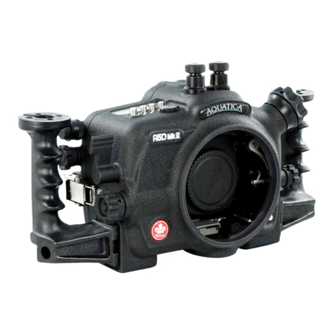
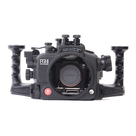
CONTROLS IN DETAIL
1. SHUTTER RELEASE LEVER : Pulling the shutter release lever back part way activates the camera meter and
autofocus. Pulling the lever back all the way fires the camera.
2. SUB-COMMAND INPUT / APERTURE KNOB : Rotates clockwise and counterclockwise. Use alone or in combination with
other controls to select or set various camera functions or modes. In “Manual” the exposure mode controls the aperture
settings (see camera manual).
3. EXPOSURE COMPENSATION CONTROL KNOB : Rotate clockwise to engage the Exposure compensation control [+/-].
Rotate the Main-Command knob to set the desired exposure compensation value.The value will appear in the Top LCD
panel and in the Viewfinder. Finally rotate the knob counterclockwise and completely up to set in the neutral position.
4. METERING SYSTEM LEVER : Rotate clockwise to engage the metering mode selector button. Then rotate Main-Command knob
clockwise or counterclockwise to select Spot, Center-Weighted or Matrix metering options. Finally rotate the knob
counterclockwise and completely up to set in the neutral position.
5. BULKHEAD CONNECTOR : For Flash Sync Cord. (Nikonos Type 5 pins).
6. EXTRA BULKHEAD CONNECTOR (OPTIONAL) : For additional Flash Sync Cord. (Nikonos Type 5 pins).
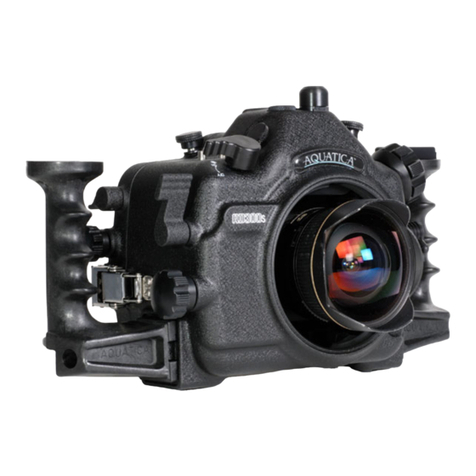
7. FOCUS/ZOOM KNOB : Turning allows manual focus of a single focus lens or rotation of the zoom mechanism of a lens.
7a. FOCUS/ZOOM PINION GEAR : Engages and operates the focus or zoom gear attached to the lens.
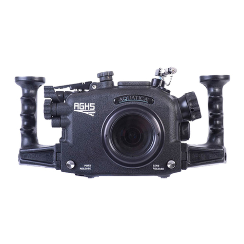
8. LENS RELEASE LEVER : activates the lens release button on the camera allowing easy removal of the lens.
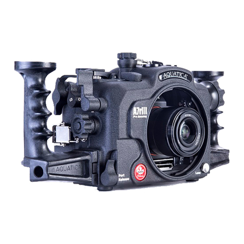
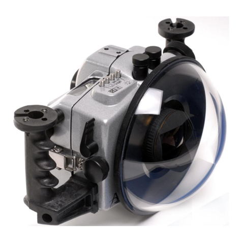
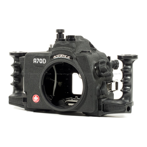
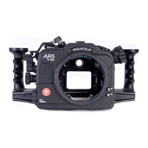
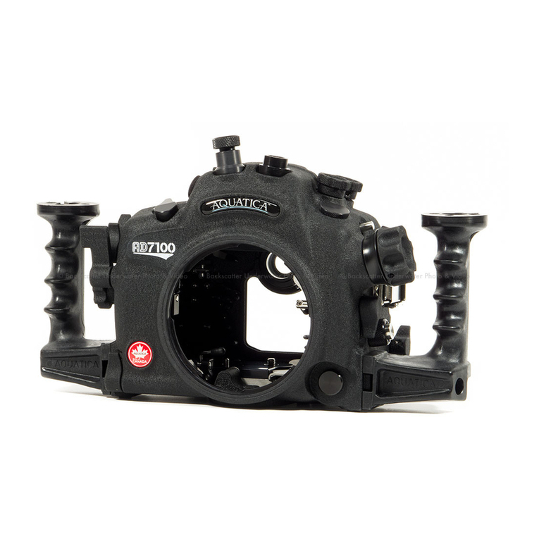
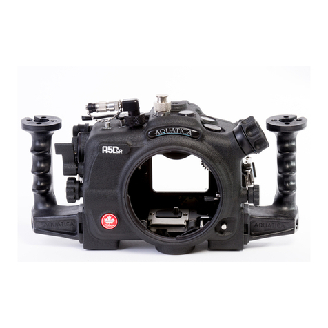
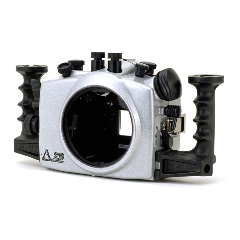
9. HAND GRIPS (X2) : Left and right grip allowing the mounting of strobe arms and accessories.
10. MOUNTING HOLE : These are 1/4-20 TPI holes that are ready to accept TLC Base Brackets or TLC Base Ball for strobe
arms or accessories.
11. HOT SHOE CONNECTOR : connects the camera to the Flash Bulkhead. Slide this Connector into the camera Hot Shoe.
When detaching do not pull the cord as this might damage the electrical connections.
12. BAYONNET MOUNTING FLANGE : allows the mounting of differents ports and extension rings on the housing.
13. CAMERA MOUNTING SADDLE : Supports the camera inside the housing in a fixed position.
14. MODE DIAL KNOB : Rotate to change the exposure mode (P,S,A,M)
15. MODE DIAL VIEWING PORT : For viewing selection of mode dial.
16. MOUNTING HOLES FOR ACCESSORY BRACKET : Two 1/4"-20 TPI holes to accept a TLC acessory bracket or TLC
base ball for mounting a strobe Arm or a modeling light.
17. VIEWFINDER : A full view of the illuminated camera viewfinder displays all necessary information.
18. MAIN-COMMAND INPUT KNOB : It rotates clockwise and counterclockwise. It can be used alone or in combination with
other controls to select or set various camera functions or modes. Refer to camera manual for in depth use.
19. TOP LCD WINDOW : displays essential camera operating data.
20. LCD ILLUMINATOR / FORMAT BUTTON : For engaging display illuminator. used for formatting card in conjunction
with button No. 22
21. AE / AF LOCK LEVER : Lock the autofocus or auto exposure according to preference.
22. SHOOTING MODE / FORMAT BUTTON : For selecting the single or continuous shooting mode, used for formatting
card in conjunction with button No. 20
23. BRACKETING BUTTON: Push to activate the bracketing function, rotate main command knob to desired exposure correction.
24. PLAYBACK BUTTON : Press to activate the monitor and review images.