FMC Technologies Smith Meter Ultra Series Instruction manual
Bulletin MNLS007 ║ Issue/Rev 0.0 (7/14)
Liquid Ultrasonic Flowmeters
Smith Meter®
Ultra™Series C Remote Display
Installation / Operation / Maintenance Manual
Rom

Page 2 • MNLS007 ║ Issue/Rev. 0.0 (7/14)
Important
All information and technical specications in this documentation have been carefully checked and compiled by the
author. However, we cannot completely exclude the possibility of errors. FMC Technologies is always grateful to be
informed of any errors.
Smith Meter® is a registered trademark of FMC Technologies.
Customer Support
Contact Information:
Customer Service
FMC Technologies Measurement Solutions, Inc.
1602 Wagner Avenue
Erie, Pennsylvania 16510 USA
P: +1 814 898-5000
F: +1 814 899-8927
www.fmctechnologies.com

Issue/Rev. 0.0 (7/14) ║ MNLS007 • Page 3
Ultra Series Remote Display I/O/M Manual Table of Contents
Table of Contents
1 – Overview....................................................................... 5
1.1. – Features .................................................................... 5
1.2. – Specifications ............................................................ 5
1.3. – Receipt of Equipment ................................................5
1.4. – Specifications ............................................................ 6
1.5. – Ultra 6c and Ultra 4c Architecture .............................. 6
1.6. – Receipt of Equipment ................................................6
1.7. – Pre-Installation Inspection ......................................... 6
2 – Installation.................................................................... 7
2.1. – Mechanical Installation ..............................................7
2.1.1. – General ...................................................................7
2.1.2. – For ATEX and IEC Installations .............................. 7
2.1.3. – For North American Installations ............................ 8
2.1.4. – All Installations - Notes ........................................... 9
2.1.5. – Installation of Cables .............................................. 9
3 – Display Control Board............................................... 11
3.1. – Wiring Examples/Information................................... 11
3.1.1. – Power Supply ....................................................... 11
3.1.2. – Network Ethernet Connection............................... 11
3.1.3. – Direct Connection to the Ultrasonic Meter ............12
4 – Powering Up the Remote Display ............................ 13
4.1. – Start-Up ...................................................................13
5 – User Display Interface............................................... 15
5.1. – Main Menu ...............................................................15
5.2. – Configuration ...........................................................15
5.2.1. – Configuration - General ........................................ 16
5.2.2. – Network Settings .................................................. 16
5.2.3. – Connections..........................................................17
5.2.4. – Modes ...................................................................19
5.3. – Maintenance Settings .............................................. 20
5.3.1. – Touch Screen Calibration ..................................... 21
5.4. – Information...............................................................21
5.5. – Reconnect ............................................................... 22
5.6. – Weights & Sealing Procedures ................................22
6 – Maintenance............................................................... 23
6.1. – Display HMI Electronics........................................... 23
6.1.1. – Board Replacement ..............................................23
6.2. – Returned Goods Policy............................................23
7 – Related Publications ................................................. 25

Page 4 • MNLS007 ║ Issue/Rev. 0.0 (7/14)

Issue/Rev. 0.0 (7/14) ║ MNLS007 • Page 5
Ultra Series C Remote Display I/O/M Manual Overview
1 – Overview
The Ultra Series Ultrasonic Flowmeter Remote Display Unit is a touch screen display designed
to be used as an HMI for FMC Technologies equipment with a web based operator interface.
The display is enclosed in an explosion proof housing and is designed to be located outdoors
and in hazardous environments. The Remote Display Unit includes all software for configuring
connections to the desired equipment and includes security functions for compliance with WELMEC
standards for weights and measures. Once configured, the display will automatically connect to
the desired Ultra Series flowmeter upon start up.
1.1 Features
• Touch Screen Display – The touch screen display is pressure sensitive and can
be activated with gloved hands.
• Security – The display includes built in security features for compatibility with
WELMEC standards for custody transfer.
• Configurable – The display can be configured to search for any FMC Technologies Ultra
Series meter on the network. Once configured the display will automatically connect to the
configured device.
• Automatic Connection – Once configured the display will automatically connect
to the configured device upon reboot.
1.2 Specifications
See specification sheet SSLS008, 5.7" Remote Display.
1.3 Receipt of Equipment
When the equipment is received, the outside packing case should be checked
immediately for any shipping damage. If the packing case has been damaged, the local
carrier should be notified at once regarding their liability. Carefully remove the unit from
its packing case and inspect for damage.
If damage has occurred during shipment or parts are missing, a written report should
be submitted to the Customer Service department by using the contact information at
the beginning of this manual.
Prior to installation, the unit should be stored in its original packing case and protected
from adverse weather conditions and abuse. Throughout the installation process, the
electronics should be protected from adverse weather conditions.

Page 6 • MNLS007 ║ Issue/Rev. 0.0 (7/14)
Ultra Series C Remote Display I/O/M Manual Overview

Issue/Rev. 0.0 (7/14) ║ MNLS007 • Page 7
Ultra Series C Remote Display I/O/M Manual Installation
2 – Installation
2.1. Mechanical Installation
2.1.1. General
The display is designed to be mounted to a plate through the holes tapped in to the rear
of the housing using size M6 x 1.8 screws.
The display unit must be supplied with an Ethernet RJ45 connection and 24 VDC power.
The cable, conduit and conduit fittings for these connections must meet installation
requirements, such as hazardous area classifications, humidity, temperature, voltage,
current and others. All conduit connections must be installed with approved conduit seals
within the required distance according to the applicable electrical code(s).
The touch screen is protected by an intrinsic safe barrier. The enclosure must be
grounded as per national electrical code regulations, for example NEC/CEC etc.
2.1.2. For ATEX and IEC Ex Installations
The following installation instructions apply for the certified equipment listed in
the equipment covered portion of the table below as per section 1.06 of Annex II of
Directive 94/9/EC (ATEX Directive):
Standards used:
IEC 60079-0 6th Edition, EN 60079-0: 2012, UL 60079-0 4th Edition
IEC 60079-1 6th Edition, EN 60079-1: 2007, UL 1203 4th Edition
IEC 60079-11 6th Edition, EN 60079-11: 2012, UL 60079-ll 5th Edition, UL 913 7 Edi-
tion UL 1203 4th Edition
Cable entries must be in accordance to EN/IEC 60079-1 section 13.
For wiring systems utilizing cable glands, the gland and/or thread adaptor must be
Page 8 • MNLS007 ║ Issue/Rev. 0.0 (7/14)
Ultra Series C Remote Display I/O/M Manual Installation
Ex d certified. The cable end must be securely installed and, depending on the cable
type, be properly protected from mechanical damage.
For wiring systems utilizing conduit, an Ex d certified sealing device must be used
immediately at the entrance of the enclosure. Any unused entry must be suitably blocked
with an Ex d certified plug.
The maximum ambient temperature for the enclosure is 60°C; if the enclosure is directly
mounted to a process piping system that exceeds this value then the enclosure shall
be remotely mounted to guarantee the 60°C ambient is not exceeded.
Equipment bonding shall be provided at the external grounding facility terminal.
External connection is not required when using metallic conduit or armored cable.
CAUTION: To prevent ignition of hazardous atmospheres and to prevent electrical
shock, disconnect from supply circuits before opening, keep tightly closed when circuits
are in operation.
WARNING: Contains internal battery-powered circuit to prevent ignition of hazardous
atmospheres, do not open enclosure unless area is known to be non-hazardous. To
reduce the risk of ignition of hazardous atmospheres, conduit runs must have a sealing
fitting connected within 18 inches of the enclosure. Substitution of components may
impair intrinsic safety.
Special conditions for safe use:
• Select wiring and cable glands suitable for 90°C operation.
• Contact manufacturer at address listed for information on the dimensions of the
flameproof joints.
FMC Technologies Measurement Solutions, Inc.
1602 Wagner Avenue
Erie, Pennsylvania 16510
USA
2.1.3. For North American Installations:
Conduit connections must be in accordance to: USA – National Electric Code (NFPA
70), Canada – Canadian Electric Code (CSA C22.1).
A listed seal-off box must be used immediately at the entrance of the enclosure. (i.e.:
within 3 inches). Any unused entry must be suitably blocked with a suitable listed plug.
Marking Equipment Covered Certicate
Ex d ib IIB T5 Gb
IP66
Tamb = -40°C to +60°C
Remote Mounted
Display
DEMKO 13 ATEX
1204991X
IEC Ex UL 13.0019X

Issue/Rev. 0.0 (7/14) ║ MNLS007 • Page 9
Ultra Series C Remote Display I/O/M Manual Installation
2.1.4. All Installations – Notes
CAUTION: To prevent ignition of hazardous atmospheres, disconnect from supply cir-
cuit before opening any enclosure. Keep tightly closed when circuits are in operation.
WARNING: Contains internal battery-powered circuit. To prevent ignition of hazardous
atmospheres, do not open enclosure unless area is known to be non-hazardous.
DO NOT SWITCH POWER ON until all questions pertaining to installation wiring are
resolved. Any damage caused by unauthorized operation will void the warranty.
CAUTION: The cable installation must be performed according to the relevant cabling
lists and/or connection diagrams.
2.1.5. Installation of Cables
Due to customer or location specific requirements, the cables for communication and
power supply lines are not a part of the delivery. However, the technical specifications
for the cables MUST be followed. Prior to installation, these requirements must be
checked. The number of and types of cables are dependent on options utilized by the
end customer. A set of wiring diagrams are available covering the different options later
in this manual.
Cables must be protected against mechanical damage.
Be aware of the minimum bending radius of the cable. The bending radius for multi-
core cable is normally 6 times the diameter. However, the minimum bending radius for
a fiber optic cable may vary from this and must be checked with the cable manufacturer
in each case.

Page 10 • MNLS007 ║ Issue/Rev. 0.0 (7/14)
Ultra Series C Remote Display I/O/M Manual Installation

Issue/Rev. 0.0 (7/14) ║ MNLS007 • Page 11
Ultra Series C Remote Display I/O/M Manual Installation
3 – Display Control Board
3.1. Wiring Examples / Information
3.1.1. Power Supply
The electronics are designed to be powered by 24 VDC, +20% / -15%, 7W.
The shield of the cable should be connected only at the electronic enclosure,
via the cable gland.
Connect input power cable to connector CN4
DC Input Wire Terminal
24 VDC (+) CN4-1
24 VDC (common) CN4-2
Ground CN4-3
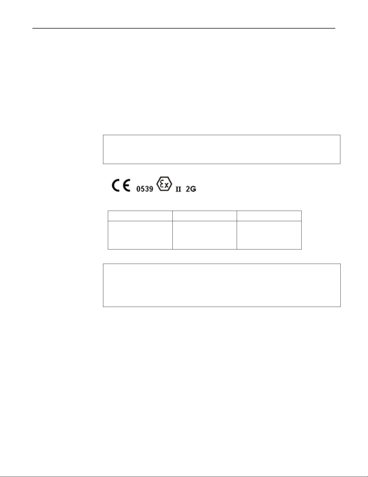
3.1.2. Network Ethernet Connection
The display utilizes ANSI/IEEE 802.3 Ethernet operating at 10/100 Mbps. The 10/100
Base-TX connection is made to the RJ45 connector at ETH1. The display unit will need
to be able to see the IP address of the ultrasonic meter from this network connection in
order to function. Refer to Configuration (Section 5.2) of this manual for details on
connecting to the ultrasonic meter.
Comm. Port Connection Port
10/100 Base-TX ETH1
Page 12 • MNLS007 ║ Issue/Rev. 0.0 (7/14)
Ultra Series C Remote Display I/O/M Manual Display Control Board
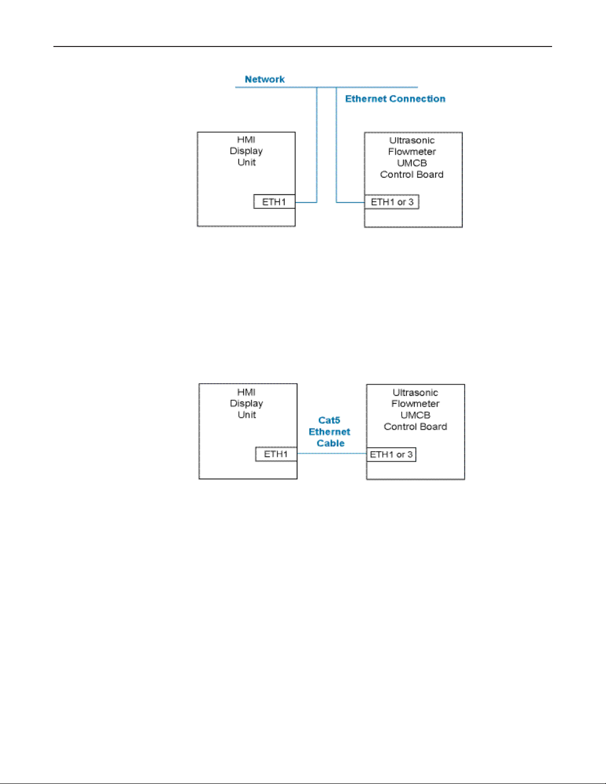
3.1.3. Direct Connection to the Ultrasonic Meter
The display unit can also be connected directly to the Ultrasonic meter using a CAT5
Ethernet cable (or better). Note that the Remote Display will still need to be configured
with the Serial Number or IP Address of the ultrasonic meter to function. Refer to
Configuration (Section 6.2) of this manual for details on connecting to the ultrasonic
meter.
Maximum cable distance: 100m (328ft)

Issue/Rev. 0.0 (7/14) ║ MNLS007 • Page 13
Ultra Series C Remote Display I/O/M Manual Powering Up the Remote Display
4 – Powering Up the Remote Display
Before powering on the display unit, verify that the following items are completed:
• Display unit has been installed securely to a fixed mounting location.
• Power and network connections have been checked for proper wiring and
connection integrity.
• All conduit and/or gland connections are in adherence to applicable electrical codes.
When power is applied to the unit it will go through a boot sequence and the unit will
attempt to connect to the configured device. If the display has not been configured or if
it fails to connect to the desired device, the display will return to the Main Menu.
4.1. Start-Up
Upon power up the unit will proceed through the following boot sequence:
1. FMC Technologies logo screen with boot progress bar.
2. For a short period, a configuration icon is shown (gears graphic); if this button is
pressed, the connection sequence in the next item is skipped and the display
connects immediately to the Display main menu.
3. If the display is configured, it will attempt to connect with the host device:
a. If the Primary URL is configured, the display will attempt to connect to this
host. If the Primary URL fails it will try to connect to the device with the
specified "Device Serial Number".
b. If a host serial number is configured, the display will search the network for
an FMC Technologies device with the specified serial number, obtain an IP
address, and attempt to connect with that host. If it fails with the device serial
number it will attempt to connect to the secondary URL.
c. If a fallback URL is configured the Display will attempt to connect to that host.
4. If step 2 is unsuccessful in connecting to any configured device or if the
Remote Display has not been configured, the Remote Display main menu will
be shown. From the Main Menu the connection settings can be configured and
the connection sequence repeated.

Page 14 • MNLS007 ║ Issue/Rev. 0.0 (7/14)
Ultra Series C Remote Display I/O/M Manual Powering Up the Remote Display
Issue/Rev. 0.0 (7/14) ║ MNLS007 • Page 15
Ultra Series C Remote Display I/O/M Manual Display User Interface
5 – User Display Interface
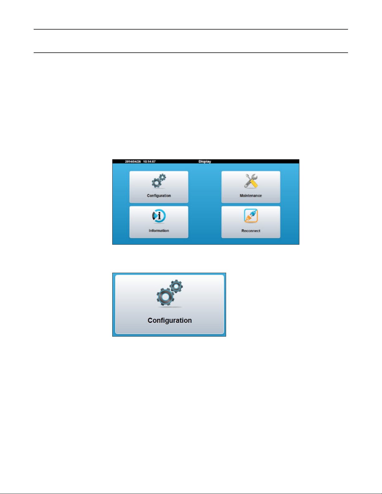
5.1. Main Menu
The main menu will be displayed if the display does not connect to a device after pow-
ering up. The main menu can also be accessed by interrupting the startup process by
tapping the configuration icon during startup. The following information and configuration
options are presented in the display main menu:
• Configuration – settings for a connection to a device
• Maintenance – adjustment of display setting
• Information – key identification and settings data
• Reconnect – initiate a reconnection to the configured device
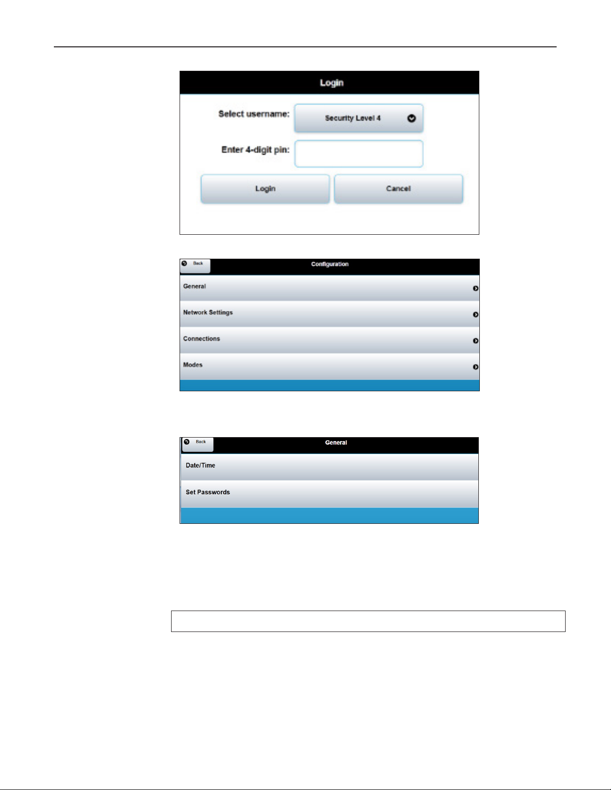
5.2. Configuration
The configuration tab is used .to set up the display to communicate with the desired
device and to set the password to control access of the display settings. A password
is required to access the configuration settings. When the Configuration Button Icon is
selected, a Login Screen will appear. There are two different levels of security access
for the Display with the following default passwords:
• Level 4 Password – 4444 Network configuration level
• Level 5 Password – 5555 Weights & Measures access level
It is recommended to change the passwords from the default value to a more secure
setting. Refer to Section 5.2.1 for password setting instructions.
Page 16 • MNLS007 ║ Issue/Rev. 0.0 (7/14)
Ultra Series C Remote Display I/O/M Manual Display User Interface
5.2.1. Configuration – General
Date/Time – Adjust the date and time of the display unit. Once the display has been
sealed the date and time adjustment will be locked out.
Set Passwords – Update the passwords for either level 4 or level 5 access. The
screen will prompt for the old password and for the new password to be entered twice
for confirmation.
The password is unique to the remote display and is not shared with the ultrasonic meter.
IMPORTANT: Record all password modifications and store in a secure location.
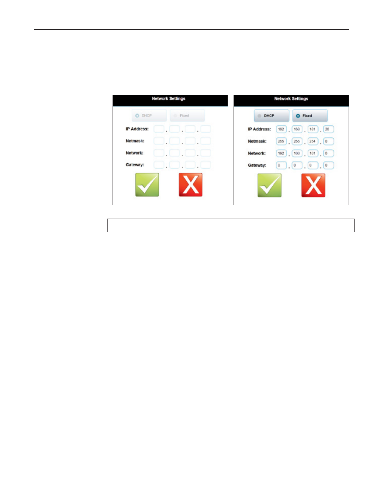
5.2.2. Network Settings
The network settings are to configure the address of the Remote Display on the net-
work. Note that this is not the address of the meter that the display is connecting to. The
display is required to have a unique IP address because it exists as a device on the IP
network. There are two modes to create the display’s network address:
DHCP - The Dynamic Host Configuration Protocol is used to request the IP address from
the network server. With this configuration checked, the DHCP server assigns a local
Issue/Rev. 0.0 (7/14) ║ MNLS007 • Page 17
Ultra Series C Remote Display I/O/M Manual Display User Interface
IP address to the Remote Display connected to the local network. This is the default
network setting from the factory.
Fixed – If the network administrator prefers to fix the IP address then this configuration
can be used. The network settings for the fixed address must be entered manually on
the display screen.
Note: The unit must be power cycled for the new settings to take effect.
5.2.3. Connections
The connections setting is used to connect to the desired ultrasonic flow meter.
Primary URL – This fixes a target IP/URL address that the display will first attempt to
connect to upon startup of the unit. In order to configure this value the IP address of
the ultrasonic flow meter must be known.
Primary Timeout – Maximum time allowed for the primary URL connection attempt, in
seconds. The URL connection attempt can be skipped by setting a zero timeout.
Device Serial Number – The unique serial number assigned to the ultrasonic meter
control board. The Ultra S eries flow meter will broadcast this Serial Number over the
network in a way that the Remote Display unit can detect. When the Remote Display
matches the configured Serial Number to a device on the network it will form a connec-
tion. The ultrasonic meter Serial Number will be displayed in the meter electronics box.
This is the recommended connection method to the ultrasonic flow meter.
Device Timeout – Maximum time to allow for the device Serial Number connection
attempt.
Secondary URL – An alternate target IP/URL address that the display will attempt to
connect to. In order to configure this value the IP address of the target device must be
known.
Secondary Timeout – Maximum time allowed for the secondary URL connection at-
tempt. The connection attempt can be skipped by setting a zero timeout.
Minimum Up Time – A minimum time since power up to allow before attempting a host
connection. Setting this to a larger value (in seconds) may be needed if the display
attempts to connect to its host before the host is ready to accept connections (for ex-
ample, if all instruments are turned on with the same power source, and the host takes
longer to boot up).

Page 18 • MNLS007 ║ Issue/Rev. 0.0 (7/14)
Ultra Series C Remote Display I/O/M Manual Display User Interface
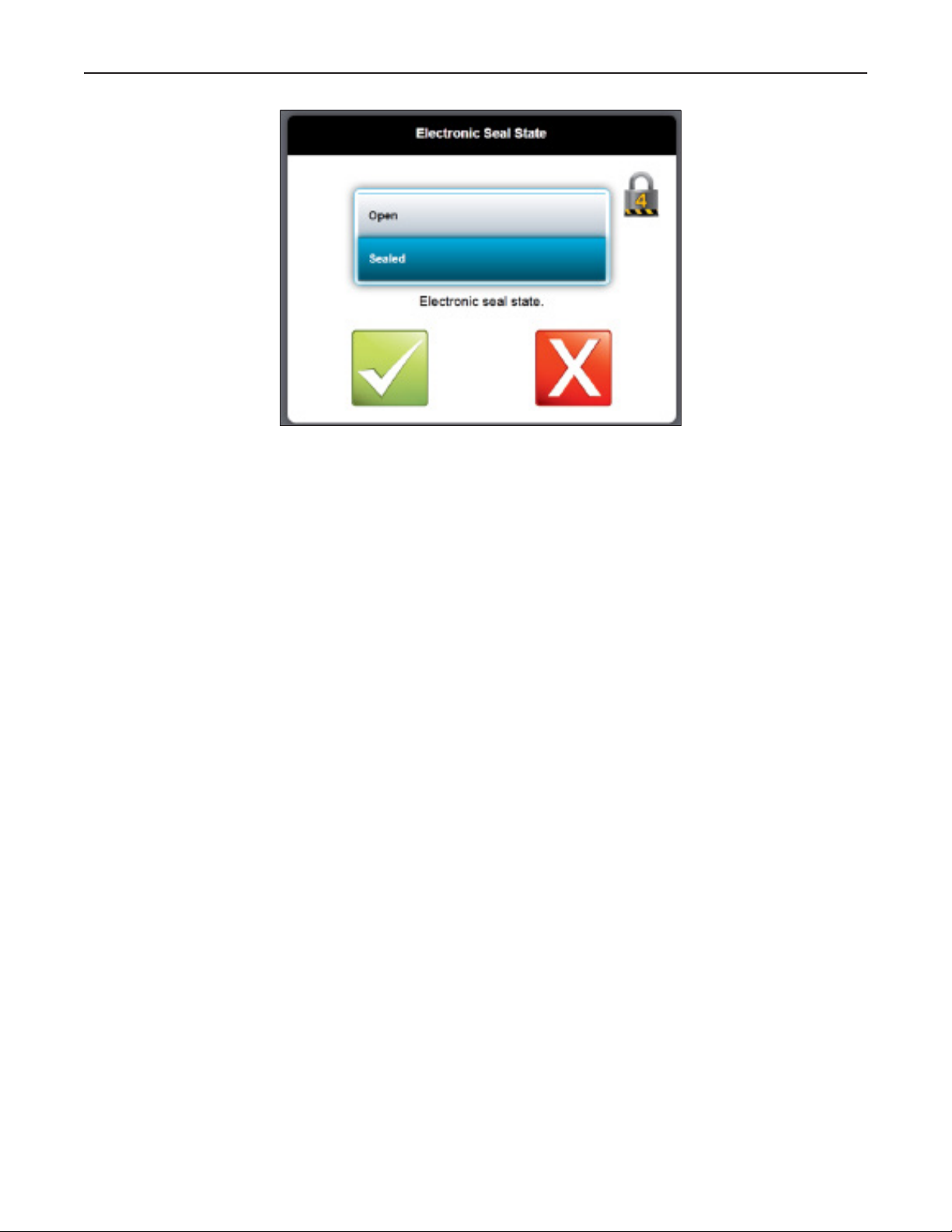
5.2.4. Modes
The Modes setting is used to configure the electronic seal and to configure the back-
lighting sleep mode for the display.
Electronic Seal State
This is used to set the electronic seal onto the display unit. Sealing locks out the ad-
justment of parameters that would be required to be fixed by a weights and measures
official. Sealing can only be opened on Level 4 or 5 access. Sealing can only be set
by Level 5 access.
Issue/Rev. 0.0 (7/14) ║ MNLS007 • Page 19
Ultra Series C Remote Display I/O/M Manual Display User Interface
Backlight Timeout
This sets the amount of time before the LCD backlight switched off for a sleep mode.
The following backlight timer duration options are available from the configuration screen.
• Always On
• 1 Minute
• 5 Minutes
• 20 Minutes
• 1 Hour

Page 20 • MNLS007 ║ Issue/Rev. 0.0 (7/14)
Ultra Series C Remote Display I/O/M Manual Display User Interface
5.3. Maintenance Settings
Allows for the unit to be reset to factory defaults by clearing all new settings.
5.3.1. Touch Screen Calibration
Opens a touch position calibration screen. This will calibrate the screen input by
displaying a series of touch screen targets and matching the input values with the known
location of the targets.
5.3.2. Password Reset
This option allows resetting all passwords to factory defaults. The procedure described
below must be followed to successfully accomplish this task. Please note that if success-
ful, the electronic seal will be broken and the action logged; if the unit is under Weights
and Measures control, it will need inspected and sealed again.
Table of contents


