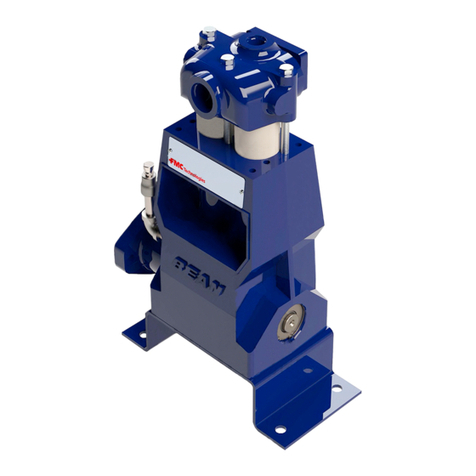
FMC M12-HD Manual

M12-HD
Piston Pump Operation &
Maintenance Manual

FMC M12-HD OPERATION AND MAINTENANCE MANUAL
2
FMC Safety Instructions
Many accidents occur through the careless operation and maintenance of mechanical
equipment. You can avoid hazards associated with the use of high-pressure
mechanical equipment provided by FMC by always following the safety precautions
listed below. If these warnings are not followed, bodily injury including death could
occur to you or other persons. FMC cannot anticipate every possible circumstance
that might involve a potential hazard, therefore the warnings listed in this publication
are not inclusive. As the user, you must decide if a particular operating mode, repair
technique, or tool is safe before performing or using.
The procedures and illustrations provided in this manual are based on the best
information available at the time of publication. Procedures, specifications, torque
requirements, and other values may be updated at any time. Always contact FMC or
your FMC equipment dealer for the most complete and current information before
starting any repair job. Contact FMC any time if you are unsure about any procedure
involving FMC equipment.
•Do not perform any operation, maintenance, or lubrication of this equipment until
you have read and understood the information provided to you in this manual and
any additional information provided by the manufacture of the equipment the pump
was supplied with.
•Never attempt a service procedure until you are certain all pressure has been
removed from the pump and the drive is disengaged and locked out.
•Never operate the pump without a relief valve, rupture disk, or other type of
overpressure safety device properly installed.
•Never exceed the rated pressure or speed of the pump for any reason.
•Never operate the pump without proper guards in place for all moving parts.
•Use caution when solvents are used to clean or degrease equipment. Most
solvents are highly flammable.

FMC M12-HD OPERATION AND MAINTENANCE MANUAL
3
TableofContents
Safety Instructions....................................................................................................2
General Features......................................................................................................4
Storage Requirements
Short Term Storage.....................................................................................5
Short Term Storage in Severe Environments..............................................5
Long Term Storage......................................................................................5
Precautions During Freezing Weather ........................................................6
Lubrication Requirements.........................................................................................7
Suction System Information......................................................................................7
Periodic Maintenance Schedule...............................................................................8
Service Procedures
Replacing Piston Cup Seals........................................................................9
Valve Replacement .....................................................................................12
Oil Seal Replacement..................................................................................15
Special Tools............................................................................................................16
Trouble-Shooting Guide ...........................................................................................17

FMC M12-HD OPERATION AND MAINTENANCE MANUAL
4
General Features
The FMC M12-HD pump is a high performance pump specially designed for the demanding
duties of horizontal drilling. The M12-HD is a piston style pump that utilizes high performance
rubber pistons running in a hardened liner for maximum component life between service. The
pump also features abrasive service valve assemblies with a special seating elements
designed to seal even when sand and other particulates are present in the fluid.
FMC pumps are extremely flexible. They can be powered by engines, electric or hydraulic
motors. FMC supplies many different types of drive connections that allow hydraulic motors
to be directly coupled to the pump frame to save space and weight. Some hydraulic motor
drives incorporate an external gear reduction system. If your pump is equipped with an
external gear reducer, consult the manufacturer for information about operation, service, and
maintenance procedures required for the equipment. FMC M12 pumps do not share common
oil reservoirs with gear reducers.
Standard M12 pump designs require a liner wash system for proper operation. Some
systems are provided directly by FMC, but most are provided by your OEM. Each system is
different, but all incorporate a recirculation tank, circulation pump, and an assortment of
hoses, tubing and nozzles that direct the wash stream to the back of the piston. Once the
wash water has been sprayed on the piston, drain piping collects it and transfers it back to the
supply tank.
The purpose of the liner wash is to provide a small amount of water to the back of the piston
during operation to cool and lubricate the piston. Without this wash water, friction between
the piston and liner generates excessive heat that can cause premature failure of the piston.
Never operate your pump without a clean supply of liner wash water to each of the three
pistons.

FMC M12-HD OPERATION AND MAINTENANCE MANUAL
5
Storage Requirements
FMC pumps come from the factory prepared for storage periods of up to six (6) months in proper
environmental conditions. Indoor storage in a dry, temperature-controlled location is always
recommended. If pumps are to be stored short term (less than six (6) months) in a severe
environment, they should be prepared using the procedures outlined in the “Short Term Storage
For Severe Environments” section below. If the pump is to be stored, or is inactive, for periods in
excess of six (6) months, it is necessary to prepare the pump as outlined in the “Long Term
Storage” section
Short Term Storage
If the pump is stored in an indoor, temperature controlled environment for less than six (6) months,
no special steps are required to prepare it for storage. As a general rule, pumps in corrosive fluid
applications should drain fluid end, flush with water or other suitable rust preventative, and blow dry
using compressed air whenever idle for periods in excess of one (1) week.
Short Term Storage for Severe Environments
Drain any fluid from pump and blow dry with compressed air. Spray a fog of preservative oil into
suction and discharge ports of fluid end, then install pipe plugs in openings. Remove the oil fill cap
(or plug) and the power end breather vent. Spray a heavy fog of preservative oil into the oil fill hole
until it can be seen coming out of the breather opening. Coat all exposed, unpainted metal
surfaces (ex. Driveshaft) with a preservative oil. Replace the oil fill cap and breather vent, then
cover the entire pump with a weather resistant covering such as a canvas or plastic tarp.
Long Term Storage
Long-term storage is defined as any period when the pump is in storage or idle for periods in
excess of six (6) months. Remove the piston cup seals and store them in a separate location with
a controlled environment where they are protected from UV exposure. If the pump has been in
service, flush the fluid end with water to clean out any of the remaining pumpage, then blow the
fluid end dry using compressed air.
Drain any remaining oil from the pump power end, then remove the power end cover to expose the
drive components. Spray all internal parts with a rust preservative that is soluble in lubricating oil
while rotating the driveshaft several turns by hand to insure complete coverage. Replace the power
end cover and add a concentrated internal rust inhibitor per manufacturers recommendations.
Spray a rust preventative onto all exterior machined surfaces paying careful attention to any
unpainted areas like the crankshaft extension. Remove the power end breather cap and store with
the piston cup seals. Cap the breather opening with a plug or other suitable means in order to keep
the preservative atmosphere sealed inside the power frame.
Never store the pump on the floor or ground. Always place it on a shelf or pallet that is several
inches above ground level. Cover the entire pump with a canvas or plastic tarp. Periodically
inspect the unit and rotate the crankshaft by hand several turns during each inspection. Drain and
replace the rust inhibitor after every six (6) months of storage.
Before operating the pump, drain the preservative and lubricating oil mixture from the power end.
Reinstall the drain plug, breather/filler cap, piston cup seals, and any other components that were

FMC M12-HD OPERATION AND MAINTENANCE MANUAL
6
removed for storage. Once these steps have been completed, fill with oil and follow normal start-up
procedures. Note that FMC can factory prepare units for extended storage for a nominal fee if
specified at the time of order.
Precautions during Freezing Weather Conditions
Freezing weather can cause problems for equipment when pumping water based fluids that
expand in volume when changing from a liquid to a frozen solid state. For example, when water is
left in a pump fluid end and exposed to freezing temperatures, the expansion of the water as it
freezes can rupture the fluid cylinder of the pump and cause permanent equipment damage or
personal injury.
Whenever the pump is stored or idle in conditions that are near or below freezing, any water based
fluids should be removed from the pump. The best way to do this is to run the pump for a few
seconds with the suction and discharge lines disconnected or open to atmosphere. This will clear
the majority of the fluid from the pumping chamber as well as the suction and discharge manifolds.
After the run, blow compressed air through the fluid end to remove all traces of fluid. If possible, lift
up the suction valve seats to insure that all fluid is drained from the pumping chamber between the
suction and discharge valves.
As an alternative to the previous procedure, a compatible antifreeze solution can be
recirculated through the fluid end. RV antifreeze, propylene glycol, is often used for this
purpose.

FMC M12-HD OPERATION AND MAINTENANCE MANUAL
7
LubricationRequirements
FMC pumps are supplied without oil in the crankcase and must be filled with oil prior to
startup. The FMC M12-HD pump requires 12 quarts (11.4 liters) of oil. Any anti-wear gear,
turbine, or hydraulic oil of the proper viscosity will work. Oils with EP, anti-foaming, or R&O
additives work well and are recommended by FMC. Use only high quality oil with a viscosity
of SAE 30 weight (ISO 100).
It is critical that condition of the oil be monitored carefully to insure it is at the proper level and
has not been contaminated. FMC provides a sight gage mounted at the rear of the pump
case that allows easy inspection of oil level and condition. The M12 pump does not require
any periodic greasing.
If your pump is equipped with an external gear reducer, consult its manufacturer for oil
requirements and service intervals. External gear reducers do not share a common oil
reservoir with the pump.
Suction System Information
FMC pumps require a minimum Net Positive Suction Head (NPSH) for proper operation. The
calculation of NPSH available for a specific pump system is a function of pump size, speed,
fluid temperature, suction pump diameter and length, and a host of other factors. This is a
complicated value for the average user to determine, so FMC has provided some general
guidelines that will work in the majority of installations.
FMC recommends that suction pipe be as short and directly routed from the source as
possible. Always use suction piping at least one pipe size larger than the pump inlet. Use
caution with flexible (fire) type hoses that can kink and restrict flow area. FMC also
recommends that a booster pump be used on all M12 pump installations. The booster pump
should be sized to provide between 20-50 psi AT THE PUMP INLET CONNECTION PORT
UNDER ALL OPERATING CONDITIONS AND SPEEDS.

FMC M12-HD OPERATION AND MAINTENANCE MANUAL
8
Preventative Maintenance
Schedule
Interval Component Type of Service Remarks
First 50 Hours Crankcase Oil Change Clean off any metal attached to the
magnetic drain plug before refilling
Daily Complete Pump Inspect Carefully go over the pump and
each component of the pump
system to insure proper operation
Daily Discharge Pressure Inspect Pressure should be steady.
Vibrations or erratic pressure
readings are a sign of valve, inlet
system, or other system problems
that must be addressed
Daily Piston Seals Inspect Check back side of piston seals for
signs of excessive leakage.
Replace promptly if leakage
becomes excessive to avoid
additional damage
Daily Crankcase Oil Inspect Check for proper level and for
signs of contamination
Daily Liner Wash System Change & Inspect Change the liner wash water and
inspect the system for proper
operation. Insure sediment has
not built up on bottom of wash
reservior
Daily Fluid End Flush Flush clean water through the
pump at the end of every day of
operation to prevent build up of
dried mud and polymer on fluid
end components
3 Months or 500
Hours Crankcase Oil Change Drain and refill with new oil. Clean
debris from magnetic drain plug

FMC M12-HD OPERATION AND MAINTENANCE MANUAL
9
Service Procedures
FMC pumps are designed to simplify all required maintenance. In addition to maintaining
clean crankcase oil at the proper level, the pistons, valves, and oil seals are all normal
expendable items that will eventually wear out and require replacement. Read and
understand each section completely before attempting to service the pump. This section
covers all normal service procedures on the fluid end of the pump. FMC drive ends do not
require routine maintenance and overhaul procedures may require special tools, equipment,
or training. If you suspect your pump requires drive end service, contact FMC or your
equipment OEM for assistance.
Replacing Piston Cup Seals
Pistons should be replaced whenever leakage increases to the point it becomes a steady
stream, not individual drops. For maximum uptime between service, FMC always
recommends that users replace all three pistons when service is required, not just the one
that shows signs of leakage.
•Pump several gallons of clean water through the pump
before service to remove the majority of mud or polymer
from the fluid end components.
•Bleed of all pressure inside pump fluid end. Shut valve on
inlet piping if provided to prevent flow of liquid into the
pump during service.
•Remove cradle cover to expose the pistons and cylinder
liners. If a liner wash system is installed on your pump,
remove any piping or nozzles that might interfere with
removal of the piston cylinders.
•Use a 3/8” socket wrench to remove the plunger clamp hex
bolts (59) and washers (58), then remove the plunger
clamp top (57) and bottom (56) from each of the three
pump cylinders.
•Slowly rotate the pump crankshaft at least one complete
revolution. With the plunger clamps removed,
friction between the piston and liner will hold each
piston assembly in the full forward (or top dead
center) position and provide working clearance for
removal of the pistons.

FMC M12-HD OPERATION AND MAINTENANCE MANUAL
10
•Use a 1-1/8” socket wrench to remove each of
the cylinder clamp hex nuts (46) and
washers (47).
•Slide each cylinder clamp (48) out over the end
of the cylinder (49) and remove.
•The remaining components of the piston-
cylinder assembly can now be removed from
the pump and taken to a workbench for further
disassembly and inspection. It may be
necessary to work the piston-cylinder assembly
from side to side while pulling back to free it
from the fluid cylinder counterbore if any corrosion has formed between parts. Cylinder o-
rings (50) may come out with the assembly or they can often stick in the fluid cylinder
counterbore.
•Push the piston assembly out through the back of the cylinder.
•Place the flats provided on the piston extension (40) in a bench vice. Remove the piston
nut (44) and dissemble the remaining components.
•Discard the piston (42), piston o-ring (45), and cylinder o-ring (50). Clean, inspect, and
save the remaining components so they can be reinstalled later. Take extra care to
inspect the bore of the piston cylinder (49). The ID of the cylinder must be smooth and
free of grooves or other defects for maximum service life of the pistons.
•The complete set of piston and cylinder components is shown below.
40 Piston Extension Rod
41 Piston Holder
42 Piston
43 Piston Washer
44 Piston Assembly Nut
45 Piston O-Ring
46 Cylinder Hex Nut
47 Cylinder Washer
48 Cylinder Clamp
49 Piston Cylinder
50 Cylinder O-Ring
51 Cylinder Stud
52 Crosshead Extension
53 Deflector Shield

FMC M12-HD OPERATION AND MAINTENANCE MANUAL
11
•Install new piston (42) and piston o-ring (45) into
the piston sub-assembly as shown (70). Note that
the piston o-rings cannot be seen in the
assembled view.
•Torque the piston nut (44) to 250 ft-lbs.
•Use a small amount of oil to lubricate the OD of
the piston, then insert the piston sub-assembly
(70) into the front end of the piston cylinder as
shown. Use a press or rubber mallet to drive the
piston to the approximate center of the piston
cylinder.
•Install new cylinder o-rings (50) in the piston
cylinder. Use a dab of grease to hold the o-
ring in the groove.
•Place the piston-cylinder assembly into the
counterbore of the fluid end and push in firmly
until it is seated at the base of the
counterbore.
•Slide the cylinder clamp (48) over the cylinder
and into position over the cylinder studs.
•Install and tighten the cylinder hex nuts (46)
and washers (47). Torque the nuts to 125 ft-
lbs in three stages to prevent cocking of the
cylinder.
•Use a wrench on the flats of the piston
extension (40) to twist and pull it up to proper
position in the crosshead extension (52). If the
assembly is properly aligned, the quill on the
end of the piston extension should easily slide
into the bore of the crosshead extension.
•Reconnect the plunger clamp assembly and
torque the hex bolts (59) to 5 ft-lbs.
•Reconnect liner wash piping that was removed
for service (if equipped) and replace the cradle
cover.

FMC M12-HD OPERATION AND MAINTENANCE MANUAL
12
Valve Replacement
Valves require replacement whenever pump pulsations levels begin to increase resulting in
rough, erratic operation. Inability to maintain proper discharge pressure is another sign that
valves have worn to the point where they require replacement. For maximum uptime
between service, FMC recommends that all 6 complete valve assemblies be replaced
whenever this service is performed, not just the valve (or components of the valve) that show
visible signs of damage.
•Pump several gallons of clean water through the
pump before service to remove the majority of mud
or polymer from the fluid end components.
•Bleed of all pressure inside pump fluid end. Shut
valve on inlet piping if provided to prevent flow of
liquid into the pump during service.
•Remove the valve cover hex nuts (1), washers (2),
and valve cover clamp (4). Remove the valve
cover (5) and valve cover o-ring (6) from each of
the three pump cylinders. It may be necessary to
use a pry bar in the groove provided at the base of
the valve cover to loosen it from the fluid cylinder.
•Remove the valve cover studs (4) so that the valve
puller tools can sit squarely on the top of the fluid
cylinder. The tops of the discharge valve cages
should now be visible through the valve cover ports
at the top of the fluid cylinder.
Note: FMC abrasive service (AR) valves are
secured to the fluid cylinder using a locking taper
mechanism. A valve puller kit is required for the
proper removal and replacement of these valves.
This kit is available from FMC under part number
5276358. Contact your equipment reseller for this part
if required.
•Use a 1-1/2” socket wrench on the hex of the valve
cage tool (11) to unscrew and remove the valve cage
(10).
•After the cage has been removed, lift the valve spring
(9) and valve (8) out through the valve cover port of the
fluid cylinder.
•The FMC valve puller tool must now be used to pull the
discharge valve seat free of the fluid cylinder.

FMC M12-HD OPERATION AND MAINTENANCE MANUAL
13
•Assemble the puller guide (19) and puller eccentric (18)
on one end of the puller stem (15) as shown. There are
two guides and two eccentrics provided in the kit. Use the
slightly larger diameter ones to remove the discharge
valve seats. The smaller diameter components will be
used later when removing the suction valve seats.
•Insert the end of the puller stem down through the discharge
valve seat (20). Work the puller guide (19) through the center
of the seat until it sits just underneath the seat. Hold the
puller stem firmly in position, then work from side to side until
the puller eccentric (18) drops down into the ID of the seat
and rests on the top of the guide as shown.
•Hold the puller stem (15) in this position and slide
the strongback (17) down over the stem until it rests
squarely on the top of the fluid cylinder (7).
•Run the puller nut (16) down the stem until it is hand
tight on the top of the strongback. You can now
release the puller stem, as the components will not
shift position with the nut in place.
•Using a heavy-duty 1-5/8” wrench, tighten the puller
nut down against the strongback to apply force to
the bottom of the valve seat. Note that up to 800 ft-
lbs of torque may be required to free the valve seat
from the fluid cylinder. Do not exceed this value.
•In many cases, torque alone will be sufficient to free
the valve seat. If unsuccessful with torque alone,
use the adapter nut (14) to connect the slide
hammer (13) and puller bolt (12) to the puller stem
(15). Leave the puller nut torqued from the previous
step. Drive the slide hammer firmly into the head of
the puller bolt to apply extra impact force to free the valve seat and lift out through the
valve cover bore in the fluid cylinder.
•Repeat the previous steps to remove the suction valves that are located just below the
discharge valves. Replace the puller guide and eccentric with the smaller diameter parts
provided in the kit to slide through the smaller bore of the suction valve. It will be
necessary to fish out the valve spring and valve from the suction valve using a variety of
hooks and loops of string or wire since the are located too deeply in the bore of the fluid
cylinder to be removed by hand.
•Remove the suction and discharge valves from the remaining two cylinders.

FMC M12-HD OPERATION AND MAINTENANCE MANUAL
14
Note: FMC M12 valves are held in place using a self-locking taper. The tapered portion
of the valve seat and the tapered portion of the fluid cylinder must be clean and dry
prior to assembly to insure proper operation. Failure to properly clean parts before
reassembly could lead to wash out of fluid cylinder or dislodgment of valve assemblies
during operation.
•To reassembly valves, first insure the fluid cylinder
and valve seats are clean, dry, and free from oil,
rust, or other debris. Use a hose, pressure washer,
or scrubbing cloth on the valve bores on the fluid
cylinder if necessary to insure proper cleanliness.
•Suction valves must be installed first, followed by
discharge valves. Valve assemblies from FMC will
arrive properly assembled and torqued direct from
the factory. If it is necessary to disassembly new
valves (or if you are not sure if they had been
previously disassembled) insure that the cage is
torqued to the seat to 25 ft-lbs before installation.
Use the hex provided on the valve cage tool (11) in
the puller kit to torque the cage.
•Lower the suction valve assembly into position on
the port taper of the fluid cylinder, lift slightly, then
allow to drop straight into the port. If the seat
drops straight it will seize in the taper and cannot
be removed by hand.
•Drive the valve assembly into the port taper using
several sharp blows from a mallet. The valve cage
can be bent or damaged if impact forces are
applied unequally or to the center of the valve
cage. To avoid bending the top of the valve cage, it
is advised to seat the valve assembly by driving on
the top of the valve stem as shown. If this is not
practical, drive on the top of the cage using a
device that spreads the force of the impact across
the full diameter of the valve cage (such as a wood
or bronze bar of the proper diameter). Make sure
valves are seated properly or they may dislodge
during operation and cause damage to the pump.
•Install the discharge valve assemblies using the
same procedures used for the suction valves.
•Install a new o-ring (6) in the valve cover. Use a
dab of grease or oil in the groove to help hold the
o-ring during assembly.
•Replace the valve cover (5) in the fluid cylinder.
Replace the studs (3), valve cover clamp (4),
washers (2), and hex nuts (1).
•Torque the valve cover hex nuts (1) to 200 ft-lbs.

FMC M12-HD OPERATION AND MAINTENANCE MANUAL
15
Oil Seal Replacement
•Remove the plunger clamp assembly from each of the three pump cylinders as outlined in
the previous sections.
•Remove the two socket head cap screws (65) from each of the oil seal holders.
•Gently pull the oil seal holder (66) free from the power end and slide out over the end of
the crosshead extension rod.
•Remove the seal gasket (68) from the power end counterbore.
•Use pliers to grip and remove the oil seals (67) from the seal holder. Note the direction of
each seal in the holder before removing. Make sure to install new seals in the same
direction.
•Replace the gasket (68) and oil seals (67) with new components then reassemble into the
pump.
•Torque the seal holder socket head capscrews (65) to 35 ft-lbs.

FMC M12-HD OPERATION AND MAINTENANCE MANUAL
16
Special Service Tools
FMC AR Valve Puller Tool
Part Number 5276358
Kit Includes the following parts:
1. Puller Bolt
2. Slide Hammer
3. Adapter Nut
4. Puller Nut
5. Strongback
6. Puller Eccentric (Discharge)
7. Puller Guide (Discharge)
8. Puller Stem
9. Puller Guide (Suction)
10. Puller Eccentric (Suction)

17
Trouble-shooting Guide
No flow from pump
Tank is empty
Inlet valve is closed
Inlet strainer is clogged with debris
Crankshaft is not turning
Insufficient pressure from pump ONLY
Pump speed is too slow
Relief valve improperly adjusted and by-passing fluid
Oversize or worn nozzle on equipment
Worn pump valves
Excessive leakage from pump seals
Insufficient flow from pump ONLY
Pump speed is too slow
Relief valve improperly adjusted and by-passing fluid
Worn pump valves
Excessive leakage from pump seals
Insufficient flow OR pressure AND rough operation
Valve Problem:
Pump valve stuck in open or closed position
Valve assembly is damaged or unseated
Valve seat is washed out
All pump cylinders not primed
nlet strainer is clogged with debris
Excessive gas in liquid due to:
Air leaks in suction line or fittings
High spots in suction line that allow formation of gas pockets
Vortex in tank near inlet pipe opening
Pump is cavitating due to:
Insufficient NPSHa (tank head or charge pressure)
Fluid viscosity is too high
Inlet line is too long and/or too small diameter
Pump runs rough, knocks, or vibrates ONLY
Loose piston assembly
Valve assembly is damaged or has unseated
Pump is cavitating due to:
Insufficient NPSHa (tank head or charge pressure)
Fluid viscosity is too high
Inlet line is too long and/or too small diameter
Worn or damaged power frame components
Pump is sucking air across worn piston cups
Suction pressure fluctuates rapidly
Pump is cavitating
Fluid leaking from pump
Piston cups are wearing and about to fail
Fluid cylinder bolts are not properly tightened
Fluid cylinder o-rings (or gaskets) are damaged
Piston assembly o-rings are damaged

18
Short piston seal life
High abrasive particle content in fluid
Wrong style or type of piston for service
Piston liner is damaged
Pump is cavitating (cylinders may run hot)
Piston assembly o-ring is damaged
Poor quality water used
Pump is allowed to run dry for extended periods of time
Liner wash system not properly maintained (if equipped)
Short valve life
High abrasive particle content in fluid
Valve assemblies only partially rebuilt during previous service
Valve assemblies damaged do to improper installation techniques
Poor quality water used
Pump is cavitating
Cracked fluid cylinder
Discharge pressure too high
Pump exposed to freezing conditions without properly draining
Hydraulic shock resulting from cavitation or entrained air
Discharge valve is stuck shut
Material or manufacturing defect
Crankshaft jerks or starts and stops rotation
V-belts are loose and slipping (if equipped)
Hydraulic system relief valve is chattering (if equipped):
Attempting to operate pump at excessively high discharge pressure
Discharge line is blocked or partially obstructed
Power end overheats (in excess of 180°F)
Discharge pressure too high
Low oil level
Improper oil viscosity
Contaminated power end oil
Pump speed is too fast
Pump is running backwards
Couplings are misaligned
V-belt drive tension is too tight
Pump located too close to heat source
Worn or damaged power frame bearings
Broken crankshaft or connecting rod
Pump exposed to freezing conditions without proper draining
Discharge pressure too high
Suction pressure too high
Hydraulic shock due to cavitation
Material or manufacturing defect
Broken Fluid End Bolts
Bolt or nut not properly torqued
Discharge pressure too high
Excessive piping loads on fluid end
Power end oil is contaminated
Pump has been operated with failed piston cup for extended periods of time
Use of high-pressure wash wand to clean near breather or oil seal areas
Deflector shields are missing or damaged
Crosshead extension oil seals are damaged or improperly installed
Excessive capacity in liner wash system
Improperly adjusted liner wash nozzle


Division Headquarters
FMC Fluid Control Division
6677 North Gessner Road
Houston, TX 77040
Phone 713.510.6800 • Fax 713.510.6806
Manufacturing & Customer Service
FMC Fluid Control Operation
2825 West Washington Avenue
Stephenville, TX 76401
Phone 800.643.6254 or 254.968.2181 • Fax 254.965.8278
Internet & E-Mail
http://www.fmcenergysystems.com/fcd/pumps
Table of contents
Other FMC Water Pump manuals
Popular Water Pump manuals by other brands

Standard Pump
Standard Pump SPFP05 Service & operating manual

EINHELL
EINHELL GC-DP 1340 G operating instructions

LEYBOLD
LEYBOLD RUVAC WS 251 Installation and operating instructions

Pentair
Pentair MYERS MDC Series Installation and operation manual

Franklin Electric
Franklin Electric Little Giant VCC-20S owner's manual

SMC Networks
SMC Networks LSP1 1 Series quick start guide

KSB
KSB Calio Installation & operating manual

Gude
Gude GP 18-0 Translation of the original instructions

Edwards
Edwards E1M18 instruction manual

DROPSA
DROPSA LOCOPUMP User and maintenance manual

Hydromatic
Hydromatic HPGLX200 Installation and service manual

Graco
Graco BULLDOG HYDRA-CAT E Series Instructions-parts list