FMC M28 User manual

Doc. No.: OMS500000104
Rev: A Page 1 of 42
Subject to contractual terms and conditions to the contrary, this document and all the information contained herein are the confidential and exclusive
property of FMC Technologies, and may not be reproduced, disclosed, or made public in any manner prior to express written authorization by FMC.
OPERATION, MAINTENANCE, & STORAGE PROCEDURE
M28 MANUAL
Rev ECN No. Date Reviewed By Approved By Status
A 5011457 30-Jan-04 Storey, Bryan T. Herold, John R. RELEASED
Summary:
This is an operations, storage and maintenance manual for an M28 pump. The M28 is a seven
inch stroke triplex positive displacement pump.
Doc. No.: OMS500000104
Rev: A Page 2 of 42
Subject to contractual terms and conditions to the contrary, this document and all the information contained herein are the confidential and exclusive
property of FMC Technologies, and may not be reproduced, disclosed, or made public in any manner prior to express written authorization by FMC.
Table of Contents
Section Title Page
1.0 Important Safety Instructions ....................................................5
2.0 M28 Pump Features....................................................................6
3.0 Storage Instructions...................................................................7
3.1 Short Term Storage.......................................................................7
3.2 Short Term Storage for Severe Environments..............................7
3.3 Long Term Storage.......................................................................7
3.4 Precautions during Freezing Weather Conditions.........................8
4.0 Installation Guidelines................................................................9
4.1 General Location...........................................................................9
4.2 Mounting Pump to Foundation and Power Source........................9
4.3 Suction Piping Recommendations................................................9
4.4 Discharge Piping Recommendations..........................................10
4.5 Multiple Pump Systems...............................................................11
5.0 How to Start a Pump.................................................................12
6.0 Recommended Lubricants.......................................................13
7.0 Preventative Maintenance Chart..............................................14
8.0 Component Parts List...............................................................15
9.0 Service Procedures...................................................................19
9.1 Replacing Plunger Packing.........................................................19
9.2 Removing the Fluid Cylinder.......................................................22
9.3 Replacing Plunger Rod Oil Seals................................................23
9.4 Replacing Valves........................................................................26
9.5 Servicing the Power End.............................................................26

Doc. No.: OMS500000104
Rev: A Page 3 of 42
Subject to contractual terms and conditions to the contrary, this document and all the information contained herein are the confidential and exclusive
property of FMC Technologies, and may not be reproduced, disclosed, or made public in any manner prior to express written authorization by FMC.
10.0 Fastener Torque Requirements...............................................33
11.0 Special Service Tools...............................................................34
12.0 Trouble-Shooting Pumps.........................................................36
13.0 Ordering Parts...........................................................................39
14.0 Glossary of Commonly Used Terms .......................................40
15.0 Reference Information..............................................................42
Doc. No.: OMS500000104
Rev: A Page 4 of 42
Subject to contractual terms and conditions to the contrary, this document and all the information contained herein are the confidential and exclusive
property of FMC Technologies, and may not be reproduced, disclosed, or made public in any manner prior to express written authorization by FMC.
List of Figures
Figures Page
Figure 1: Power End Components..................................................................................15
Figure 2: Fluid End Components ....................................................................................16
Figure 3: Plunger Packing Replacement.........................................................................20
Figure 4: Cylinder Cover Removal..................................................................................21
Figure 5: Removal of Fluid Cylinder................................................................................23
Figure 6: Oil Seal Replacement......................................................................................25
Figure 7: Back Cover Removal.......................................................................................27
Figure 8: Power End Disassembly..................................................................................28
Figure 9: Crank Shaft Bearing Removal..........................................................................29
Figure 10: Crankshaft Removal ......................................................................................30
Figure 11: Cross Head and Con Rod Removal...............................................................31
Figure 12: Crankshaft Lifting Tool...................................................................................34
Doc. No.: OMS500000104
Rev: A Page 5 of 42
Subject to contractual terms and conditions to the contrary, this document and all the information contained herein are the confidential and exclusive
property of FMC Technologies, and may not be reproduced, disclosed, or made public in any manner prior to express written authorization by FMC.
1.0 Important Safety Instructions
WARNING:
MANY ACCIDENTS OCCUR EVERY YEAR THROUGH
CARELESS USE OF MECHANICAL EQUIPMENT. YOU
CAN AVOID HAZARDS ASSOCIATED WITH HIGH-
PRESSURE EQUIPMENT BY ALWAYS FOLLOWING
THE SAFETY PRECAUTIONS LISTED BELOW.
Shut down or disengagethe pump and all accessory equipment before attempting any type of service.
Failure to do this could cause electrical shock or injury from moving pump parts or components under high pressure.
Bleed off all pressureto the pump and piping before attempting any maintenance to the pump. Failure to do
so may spray water or chemicals at high pressure onto service personnel.
Never operate the pump without a pressure relief valve, burst disc, or other type of properly sized
overpressure safety device installed.
Always use a pressure gagewhen operating the pump. The pressure must never exceed the maximum
pressure rating of the pump or damage may occur. This damage can cause leakage or structural damage resulting
in injury to personnel.
Insure that no valves are placed between the pump and pressure relief valve. If the pump is
started with a closed or restricted valve in line before the pressure relief valve, the pump may build up pressure in
excess of its rated limits and burst causing injury to personnel.
Use shields or covers around pumpswhen pumping hot water, chemicals, or other hazardous liquids.
This precaution can prevent the exposure of service personnel to these fluids should leakage occur.
Always use guardson all belt drives and couplings. Guards can prevent personnel from becoming entangled
and injured in rotating parts.
Use extreme caution with solventsused to clean or degrease equipment. Most solvents are highly
flammable. Observe all safety instructions on packaging.
Never modify the pump to perform beyond its rated specifications.

Doc. No.: OMS500000104
Rev: A Page 6 of 42
Subject to contractual terms and conditions to the contrary, this document and all the information contained herein are the confidential and exclusive
property of FMC Technologies, and may not be reproduced, disclosed, or made public in any manner prior to express written authorization by FMC.
2.0 M28 Pump Features
Exceptional design, workmanship, materials, and over 100 years experience building pumps are
features you’ll find built into every FMC pump.
Oil level sight gage
allows remote
monitoring of oil
level and condition.
Choice of straight-keyed shaft or optional
mounting flange and spline for direct
coupling of hydraulic motor drives.
Magnetic drain
plugs remove
tramp iron from
the oil bath.
State of the art plungers and
packing provides unmatched
service life in even the toughest
applications.
Integrally cast and
machined feet to provide
rigid and precise
mountin
g
.
Individual clamped cylinder
covers allow removal of
plungers through the front
of the fluid c
y
linder.
Abrasion resistant
or disc type valves
feature tough,
durable materials
and generous flow
areas to extend
service life.
Plunger rods and packing can be
removed and replaced without
disassemblin
g
the power end.
Heavy-duty power ends are machined from a one-
piece gray iron casting for long service life. All
pumps incorporate a reliable splash lube system
with gravity feed return to sump. Pressure
lubrication of internal bearin
g
s is an option.
Doc. No.: OMS500000104
Rev: A Page 7 of 42
Subject to contractual terms and conditions to the contrary, this document and all the information contained herein are the confidential and exclusive
property of FMC Technologies, and may not be reproduced, disclosed, or made public in any manner prior to express written authorization by FMC.
3.0 Storage Instructions
Proper storage of your FMC pump will insure that it is ready for service when needed. Follow
the guidelines below that fit the requirements of your application
FMC pumps come from the factory prepared for storage periods of up to six (6) months in
proper environmental conditions. Indoor storage in a dry, temperature-controlled location is
always recommended. If pumps are to be stored short term (less than six (6) months) in a
severe environment, they should be prepared using the procedures outlined in the “Short Term
Storage For Severe Environments” section below. If the pump is to be stored, or is inactive, for
periods in excess of six (6) months, it is necessary to prepare the pump as outlined in the “Long
Term Storage” section
3.1 Short Term Storage
1. If the pump is stored in an indoor, temperature controlled environment for less than six
(6) months, no special steps are required to prepare it for storage. As a general rule for
pumps in corrosive fluid applications, the fluid end should be drained, flushed with water
or other non-corrosive cleanser and blown dry using compressed air whenever idle.
3.2 Short Term Storage for Severe Environments
1. Drain any fluid from pump, flush the fluid end with water to clean out any of the
remaining pumpage and blow dry with compressed air. Spray a fog of preservative oil
into the suction and discharge ports of fluid end, then install pipe plugs in openings.
Remove the oil fill cap (or plug) and the power end breather vent. Spray a heavy fog of
preservative oil into the oil fill hole until it can be seen coming out of the breather
opening. Coat all exposed, unpainted metal surfaces (for example, the Driveshaft) with a
preservative oil. Replace the oil fill cap and breather vent, then cover the entire pump
with a weather resistant covering such as a canvas or plastic tarp.
3.3 Long Term Storage
1. Long-term storage is defined as any period when the pump is in storage or idle in excess
of six (6) months. If the pump has been in service, flush the fluid end with water to clean
out any of the remaining pumpage, then blow the fluid end dry using compressed air.
2. Drain all remaining oil from the pump power end. Remove the rear cover to expose the
drive components. Spray all internal parts with a rust preservative that is soluble in
lubricating oil while rotating the driveshaft several turns by hand to insure complete
coverage. Replace the rear cover and add a concentrated internal rust inhibitor per
recommendations (see Recommended Lubricant Chart, page 9).
Doc. No.: OMS500000104
Rev: A Page 8 of 42
Subject to contractual terms and conditions to the contrary, this document and all the information contained herein are the confidential and exclusive
property of FMC Technologies, and may not be reproduced, disclosed, or made public in any manner prior to express written authorization by FMC.
3. Spray a rust preventative onto all exterior machined surfaces paying careful attention to
any unpainted areas like the crankshaft extension and plunger rods. Remove the power
end breather cap and store in a dry place. Cap the breather opening with a plug or other
suitable means in order to keep the preservative atmosphere sealed inside the power
frame.
4. Never store the pump on the floor or ground. Always place it on a shelf or pallet that is
several inches above ground level. Cover the entire pump with a canvas or plastic tarp.
Periodically inspect the unit and rotate the crankshaft by hand several turns during each
inspection. Drain and replace the rust inhibitor after every six (6) months of storage.
5. Before operating the pump, drain the preservative and lubricating oil mixture from the
power end. Reinstall the drain plug, breather/filler cap, and any other components that
were removed for storage. Once these steps have been completed, follow the normal
pump start up procedures outlined in this manual. FMC can factory prepare units for
extended storage for a nominal fee if specified at the time of order.
3.4 Precautions during Freezing Weather Conditions
1. Freezing weather can cause problems for equipment when pumping water based fluids
that expand in volume when changing from a liquid to a frozen solid state. For example,
when water is left in a pump fluid end and exposed to freezing temperatures, the
expansion of the water as it freezes can rupture the fluid cylinder of the pump and cause
permanent equipment damage or personal injury.
2. Whenever the pump is stored or idle in conditions that are near or below freezing, any
water based fluids should be removed from the pump. The best way to do this is to run
the pump for a few seconds with the suction and discharge lines disconnected or open to
atmosphere. This will clear the majority of the fluid from the pumping chamber as well
as the suction and discharge manifolds. After the run, blow compressed air through the
fluid end to remove all traces of fluid. If possible, lift up the suction valve seats to insure
that all fluid is drained from the pumping chamber between the suction and discharge
valves.
3. As an alternative to the previous procedure, a compatible antifreeze solution can be
circulated through the fluid end. RV antifreeze, propylene glycol, is recommended for
this purpose.
Doc. No.: OMS500000104
Rev: A Page 9 of 42
Subject to contractual terms and conditions to the contrary, this document and all the information contained herein are the confidential and exclusive
property of FMC Technologies, and may not be reproduced, disclosed, or made public in any manner prior to express written authorization by FMC.
4.0 Installation Guidelines
A proper installation is the key to optimum performance, longer service life, and reduced
maintenance requirements. Take time to thoroughly plan all aspects of your installation.
4.1 General Location
It is important to position the pump on a flat, level surface to assist the splash oil lubrication
system. Whenever possible, the pump should be mounted in a clean, dry location with
sufficient lighting and adequate space for easy inspection and maintenance. Locate the pump as
close to the suction source as possible to allow for the shortest and most direct routing of the
inlet piping.
4.2 Mounting Pump to Foundation and Power Source
1. The M28 pump must be mounted in a horizontal position only. Secure the pump to the
mounting surface using the four (4) holes provided in the pump base. Check motor or
engine rotation direction to insure that the top of the pump drive shaft rotates towards the
pump fluid end when in operation.
2. For units that are V-belt driven, check the alignment of the sheaves after the unit is
installed on its permanent mounting. Tighten belts to the proper tension as recommended
by the belt manufacturer. Verify that the sheaves are in line and running parallel to each
other with a straight edge or other device. Never operate the pump without the belt guard
securely in place.
3. For direct-coupled or spline driven units, insure that the shafts are centered and parallel
when the driver is mounted to the pump. Never operate the pump without a shaft guard
securely in place.
4.3 Suction Piping Recommendations
1. Poor suction piping practices are a very common source of pump problems. To insure
proper operation it is very important to follow good design practice in the installation of
the suction system before the pump is operated. A small amount of extra time and
money invested in the piping system usually provides for better pump performance and
longer periods between service requirements. It is difficult to diagnose many pump
problems without the aid of a suction pressure gage. For this reason, FMC recommends
that a gage always be installed in the suction line directly before it enters the pump.
2. The suction line from the fluid source to pump should be as short and direct as possible.
Use rigid piping, non-collapsible hose or a combination of both as circumstances warrant
in your installation. The suction pipe size should be at least equal to or one size larger
Doc. No.: OMS500000104
Rev: A Page 10 of 42
Subject to contractual terms and conditions to the contrary, this document and all the information contained herein are the confidential and exclusive
property of FMC Technologies, and may not be reproduced, disclosed, or made public in any manner prior to express written authorization by FMC.
than the pump inlet. Long piping runs, low suction heads, or indirect pipe routing may
require even greater oversizing of the suction line for proper operation of the pump. In
some cases it may be necessary to install a booster pump in the suction line of the pump
to obtain sufficient pressure for the pump to operate successfully.
3. The suction line must be laid out so that there are no high spots in the line where gas or
air pockets could collect. These pockets can make the pump difficult to prime and cause
rough, erratic operation. A drain valve or plug should be installed at the low point of the
suction line to allow for drainage during freezing conditions or for maintenance.
4. FMC recommends that all piping be supported independently of the pump. By
supporting the piping this way, vibrations are reduced and stress on the pump is kept to a
minimum. The use of elbows, nipples, unions, or other fittings should be minimized.
Make sure that all joints and connections are airtight. Air leaks reduce the capacity of the
pump and can result in cavitation, rough operation, and/or loss of prime. To help isolate
mechanical and hydraulic vibrations, FMC recommends the use of flexible hose
connections between the pump and any rigid piping.
5. Always insure that calculated system net positive suction head available (NPSHa)
exceeds pump net positive suction head required (NPSHr) by at least 5 feet (1.5 meters)
of water for proper operation of the pump. NPSH requirements for each pump model are
provided on the product data sheets available through FMC or you authorized FMC
reseller. FMC does not recommend using the pump in static lift conditions without prior
approval.
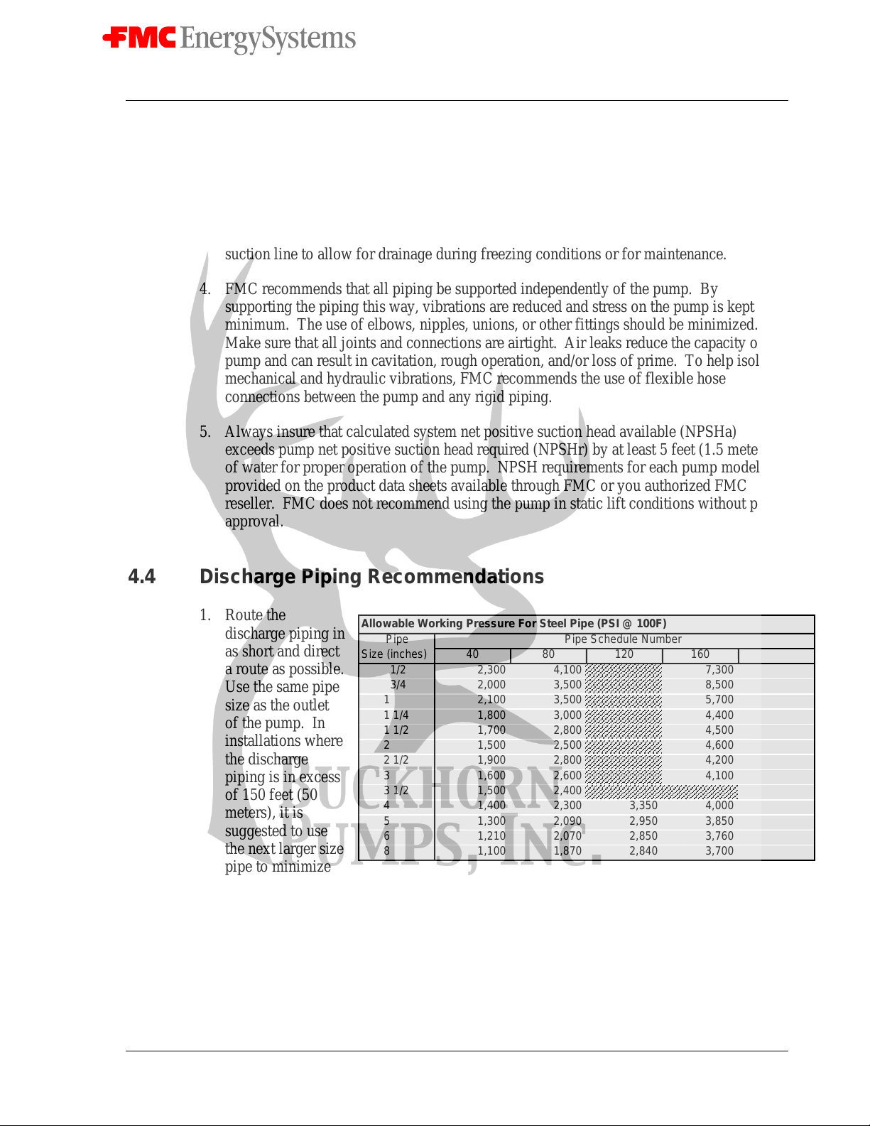
4.4 Discharge Piping Recommendations
1. Route the
discharge piping in
as short and direct
a route as possible.
Use the same pipe
size as the outlet
of the pump. In
installations where
the discharge
piping is in excess
of 150 feet (50
meters), it is
suggested to use
the next larger size
pipe to minimize
friction losses
downstream of the pump. Always use pipe or hose that is designed for your particular
pressure requirements. Inadequate pressure ratings can allow hose or pipe to fail
resulting in personal injuries or equipment damage. Normal hose pressure ratings are
clearly marked on the outer surface of the hose. Working pressure ratings for steel pipe
can be obtained from the manufacturer or from the adjacent chart.
Allowable Working Pressure For Steel Pipe (PSI @ 100F)
Pipe Pipe Schedule Number
Size (inches) 40 80 120 160 XX
1/2 2,300 4,100 7,300 12,300
3/4 2,000 3,500 8,500 10,000
1 2,100 3,500 5,700 9,500
1 1/4 1,800 3,000 4,400 7,900
1 1/2 1,700 2,800 4,500 7,200
2 1,500 2,500 4,600 6,300
2 1/2 1,900 2,800 4,200 6,900
3 1,600 2,600 4,100 6,100
3 1/2 1,500 2,400 5,600
4 1,400 2,300 3,350 4,000 5,300
5 1,300 2,090 2,950 3,850 4,780
6 1,210 2,070 2,850 3,760 4,660
8 1,100 1,870 2,840 3,700 3,560
Doc. No.: OMS500000104
Rev: A Page 11 of 42
Subject to contractual terms and conditions to the contrary, this document and all the information contained herein are the confidential and exclusive
property of FMC Technologies, and may not be reproduced, disclosed, or made public in any manner prior to express written authorization by FMC.
2. Always use a pressure gage in the pump discharge line. A properly functioning gage
mounted at the pump (and before any valves) is required to accurately determine the
operating pressure of a pump.
3. Insure that all piping is supported independently of the pump to reduce vibrations and
strain on the pump itself. The use of elbows, nipples, unions, or other fittings should be
kept to an absolute minimum. Avoid short radius 90°elbows; use two long radius 45°
elbows instead. To help isolate mechanical and hydraulic vibrations, FMC recommends
the use of flexible hose connections between the pump and any rigid piping or the use of
pulsation dampeners.
4. A properly adjusted pressure relief valve or rupture disc must be installed directly
downstream of the pump to prevent damage or injuries resulting from over pressure or
deadhead conditions. The relief valve by-pass line must be as large as the pipe outlet of
the relief valve. Never install valves in the by-pass line or between the pump and relief
valve. FMC recommends that the by-pass be returned to the suction tank or drain, not
back into the pump suction line.
4.5 Multiple Pump Systems
Special consideration must be taken to avoid vibration and pulsation problems when operating
multiple reciprocating pumps using common suction and discharge piping headers. It is
recommended that the user contact FMC or other experienced industry consultants for
assistance with the design of the system and pump in these situations.

Doc. No.: OMS500000104
Rev: A Page 12 of 42
Subject to contractual terms and conditions to the contrary, this document and all the information contained herein are the confidential and exclusive
property of FMC Technologies, and may not be reproduced, disclosed, or made public in any manner prior to express written authorization by FMC.
5.0 How to Start a Pump
ALWAYS TAKE SPECIAL PRECAUTIONS WHEN STARTING A PUMP FOR THE
FIRST TIME OR AFTER ANY EXTENDED SHUTDOWN. NEVER ASSUME THAT
SOMEONE ELSE HAS PROPERLY PREPARED THE PUMP AND SYSTEM FOR
OPERATION. ALWAYS CHECK EACH COMPONENT OF THE SYSTEM PRIOR TO
EVERY START-UP.
The checklist that follows is intended to be a general guide for starting a pump in a typical
installation. Every installation is different, and each will have different requirements to insure
safe and successful operation. It is the responsibility of the operator to determine the correct
start-up procedure for each installation.
1. Insure that the drain plugs on the bottom of the pump crankcase have been installed and
are tight. Insure that the oil level sight glass has been properly installed.
2. Check the oil level to insure that the pump is properly filled and that the oil has not been
contaminated with water or other liquids. FMC pumps are not shipped with oil in the
power frame and must be filled with the proper grade of oil prior to start-up. The M28
pump requires 13 gallons (49.2 liters) of oil. Use the chart provided in Section 6 for
assistance in selecting the correct type of oil for your service.
3. Insure that the pressure relief valve and all accessory equipment have been installed and
properly adjusted. Verify that all joints are pressure tight.
4. Open the suction line valve to allow fluid to enter pump.
5. Check to insure that power is locked out, and then turn the pump over by hand if possible
to insure free, unobstructed operation.
6. Make sure that all guards are in place and secure. Verify that all personnel are in safe
positions and that system conditions are acceptable for operation.
7. Start the pump. Whenever possible, use a bypass line for the flow to allow the pump to
start in an unloaded condition (no discharge pressure). Slowly close the bypass line to
bring the pump into full load conditions. Shut down immediately if the flow becomes
unsteady, pressure fluctuates or if unusual sounds or vibrations are noted.
Doc. No.: OMS500000104
Rev: A Page 13 of 42
Subject to contractual terms and conditions to the contrary, this document and all the information contained herein are the confidential and exclusive
property of FMC Technologies, and may not be reproduced, disclosed, or made public in any manner prior to express written authorization by FMC.
6.0 Recommended Lubricants
Few factors can influence the life of a pump more than the power end lubricant. Careful
selection of the right type of oil for your particular application will help insure optimal
performance from your pump.
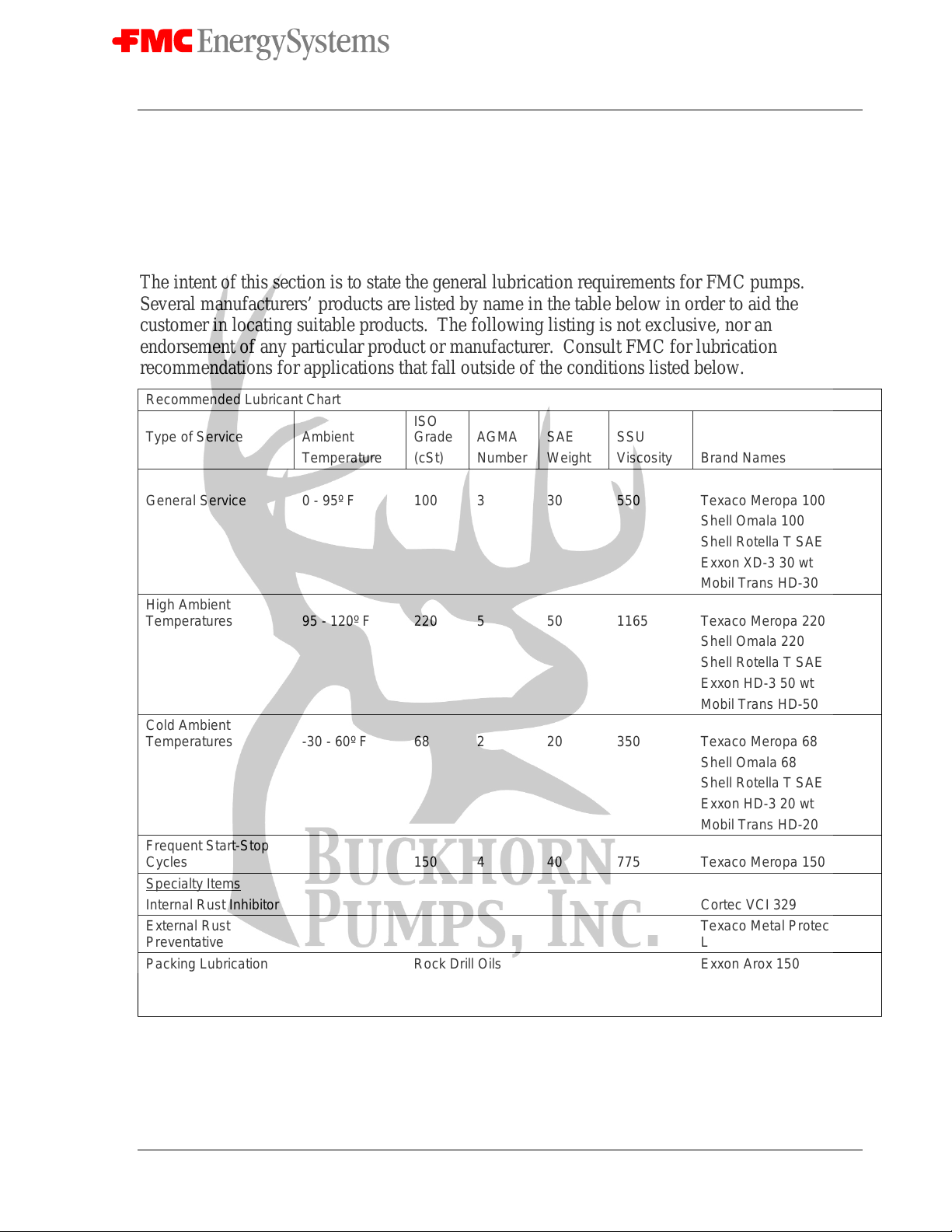
The intent of this section is to state the general lubrication requirements for FMC pumps.
Several manufacturers’ products are listed by name in the table below in order to aid the
customer in locating suitable products. The following listing is not exclusive, nor an
endorsement of any particular product or manufacturer. Consult FMC for lubrication
recommendations for applications that fall outside of the conditions listed below.
Recommended Lubricant Chart
Type of Service Ambient ISO
Grade AGMA SAE SSU
Temperature (cSt) Number Weight Viscosity Brand Names
General Service 0 - 95º F 100 3 30 550 Texaco Meropa 100
Shell Omala 100
Shell Rotella T SAE 30
ExxonXD-330wt
Mobil Trans HD-30
High Ambient
Temperatures 95 - 120º F 220 5 50 1165 Texaco Meropa 220
Shell Omala 220
Shell Rotella T SAE 50
ExxonHD-350wt
Mobil Trans HD-50
Cold Ambient
Temperatures -30 - 60º F 68 2 20 350 Texaco Meropa 68
Shell Omala 68
Shell Rotella T SAE 20
ExxonHD-320wt
Mobil Trans HD-20
Frequent Start-Stop
Cycles 150 4 40 775 Texaco Meropa 150
Specialty Items
Internal Rust Inhibitor Cortec VCI 329
External Rust
Preventative Texaco Metal Protective Oil
L
Packing Lubrication Rock Drill Oils Exxon Arox 150
Shell Toreula 150
Mobil Almo 529
Cortecis a registered trademark of Cortec Corporation, St. Paul, NM
Doc. No.: OMS500000104
Rev: A Page 14 of 42
Subject to contractual terms and conditions to the contrary, this document and all the information contained herein are the confidential and exclusive
property of FMC Technologies, and may not be reproduced, disclosed, or made public in any manner prior to express written authorization by FMC.
7.0 Preventative Maintenance Chart
Routine maintenance is an essential part of any successful pump installation. Properly
maintained FMC pumps are designed to offer years of trouble-free service.
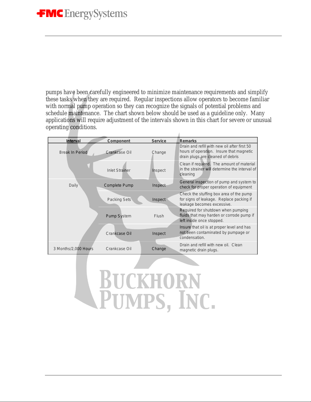
Regular maintenance and inspection will keep your pump operating at peak performance. FMC
pumps have been carefully engineered to minimize maintenance requirements and simplify
these tasks when they are required. Regular inspections allow operators to become familiar
with normal pump operation so they can recognize the signals of potential problems and
schedule maintenance. The chart shown below should be used as a guideline only. Many
applications will require adjustment of the intervals shown in this chart for severe or unusual
operating conditions.
Interval Component Service Remarks
Break In Period Crankcase Oil Change Drain and refill with new oil after first 50
hours of operation. Insure that magnetic
drain plugs are cleaned of debris
Inlet Strainer Inspect Clean if required. The amount of material
in the strainer will determine the interval of
cleaning
Daily Complete Pump Inspect General inspection of pump and system to
check for proper operation of equipment
Packing Sets Inspect Check the stuffing box area of the pump
for signs of leakage. Replace packing if
leakage becomes excessive.
Pump System Flush Required for shutdown when pumping
fluids that may harden or corrode pump if
left inside once stopped.
Crankcase Oil Inspect Insure that oil is at proper level and has
not been contaminated by pumpage or
condensation.
3 Months/2,000 Hours Crankcase Oil Change Drain and refill with new oil. Clean
magnetic drain plugs.
Doc. No.: OMS500000104
Rev: A Page 15 of 42
Subject to contractual terms and conditions to the contrary, this document and all the information contained herein are the confidential and exclusive
property of FMC Technologies, and may not be reproduced, disclosed, or made public in any manner prior to express written authorization by FMC.
8.0 Component Parts List
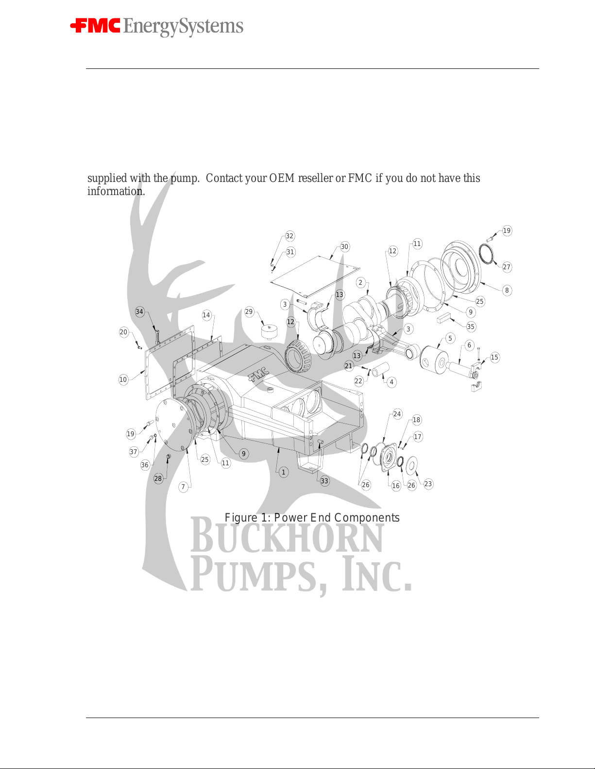
A typical M28 pump configuration is shown below for general reference purposes for service
procedures outlined in the following sections. Actual pumps supplied by FMC may use slightly
different components or configurations. To order service parts or see exact component
configurations for your particular pump, refer the cross section drawing in the literature kit
supplied with the pump. Contact your OEM reseller or FMC if you do not have this
information.
30
31
32
29 3
12
34
20
10
14
19
37
36
28 7
25 11 9
133 23
26
17
18
16
24
26
4
22
2113
356
15
35
925 8
27
19
11
12
2
13
Figure 1: Power End Components
Doc. No.: OMS500000104
Rev: A Page 16 of 42
Subject to contractual terms and conditions to the contrary, this document and all the information contained herein are the confidential and exclusive
property of FMC Technologies, and may not be reproduced, disclosed, or made public in any manner prior to express written authorization by FMC.
65
50
55
59
40
76
67
61
48
56
78 77
79
63
62
53
75
67
74
47 68
71
38
39
52
51
5869
64
54
41
73
72
73
49 65
55 59
42
57
60
70
66
43
45
46
44
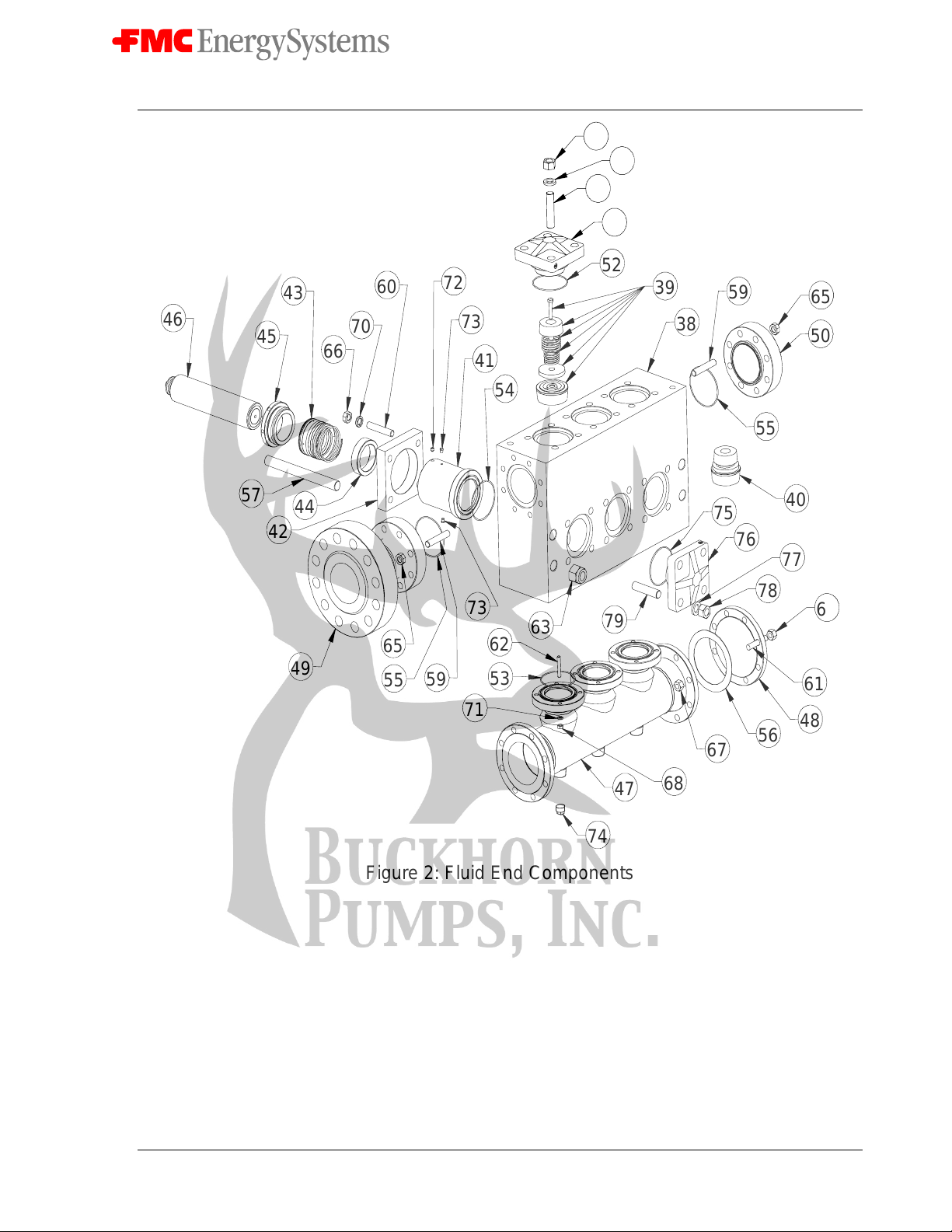
Figure 2: Fluid End Components

Doc. No.: OMS500000104
Rev: A Page 17 of 42
Subject to contractual terms and conditions to the contrary, this document and all the information contained herein are the confidential and exclusive
property of FMC Technologies, and may not be reproduced, disclosed, or made public in any manner prior to express written authorization by FMC.
Item Number Description Quantity Required
1 Power Frame 1
2 Crankshaft 1
3 Connecting Rod Assembly 3
4WristPin 3
5 Crosshead 3
6 Plunger Rod 3
7 Blind Bearing Housing 1
8 Bearing Housing 1
9 Shim As needed
10 Back Cover 1
11 Bearing Cup 2
12 Bearing Cone 2
13 Rod Bearing 6
14 Back Cover Gasket 1
15 Plunger Clamp Assembly 3
16 Seal Housing 3
17 Cap Screw(Seal Housing) 12
18 Lock Washer 12
19 Cap Screw(Bearing Housing) 12
20 Cap Screw(Back Cover) 28
21 Set Screw 3
22 Set Screw 3
23 Deflector Shield 3
24 O-ring(Seal Housing) 3
25 O-ring (Bearing Housing) 2
26 U Cup Seal 9
27 Oil Seal 1
28 Magnetic Pipe Plug 3
29 Oil Filler/Breather 1
30 Cradle Cover 1
31 Stud(Cradle Cover) 4
32 Wing Nut 4
33 Dowel Pin 2
34 Liquid Level Gage 1
35 Key 1
36 Nylon Washer 1
37 Hex Head Cap Screw 1
38 Fluid Cylinder 1
39 Discharge Valve Assembly 3
40 Suction Valve Assembly 3
Doc. No.: OMS500000104
Rev: A Page 18 of 42
Subject to contractual terms and conditions to the contrary, this document and all the information contained herein are the confidential and exclusive
property of FMC Technologies, and may not be reproduced, disclosed, or made public in any manner prior to express written authorization by FMC.
Item Number Description Quantity Required
41 Stuffing Box 3
42 Stuffing Box Clamp 3
43 Plunger Packing 3
44 Throat Bushing 3
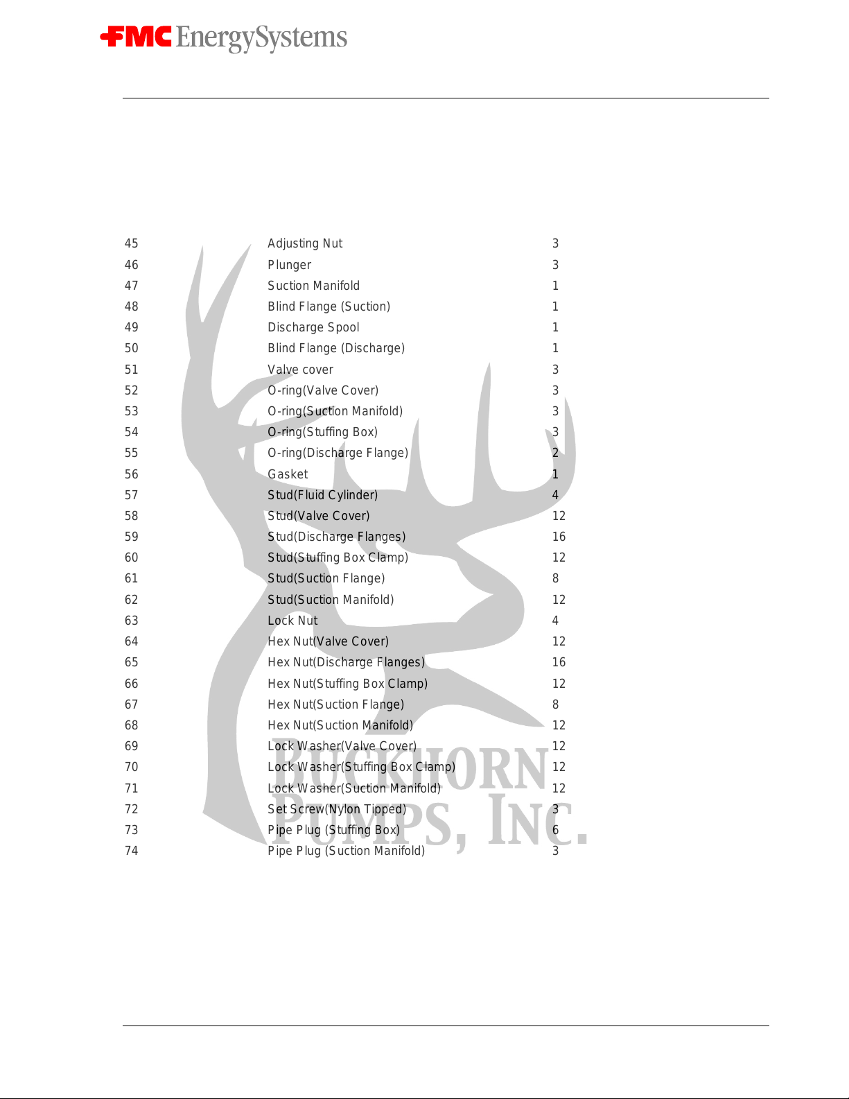
45 Adjusting Nut 3
46 Plunger 3
47 Suction Manifold 1
48 Blind Flange (Suction) 1
49 Discharge Spool 1
50 Blind Flange (Discharge) 1
51 Valve cover 3
52 O-ring(Valve Cover) 3
53 O-ring(Suction Manifold) 3
54 O-ring(Stuffing Box) 3
55 O-ring(Discharge Flange) 2
56 Gasket 1
57 Stud(Fluid Cylinder) 4
58 Stud(Valve Cover) 12
59 Stud(Discharge Flanges) 16
60 Stud(Stuffing Box Clamp) 12
61 Stud(Suction Flange) 8
62 Stud(Suction Manifold) 12
63 Lock Nut 4
64 Hex Nut(Valve Cover) 12
65 Hex Nut(Discharge Flanges) 16
66 Hex Nut(Stuffing Box Clamp) 12
67 Hex Nut(Suction Flange) 8
68 Hex Nut(Suction Manifold) 12
69 Lock Washer(Valve Cover) 12
70 Lock Washer(Stuffing Box Clamp) 12
71 Lock Washer(Suction Manifold) 12
72 Set Screw(Nylon Tipped) 3
73 Pipe Plug (Stuffing Box) 6
74 Pipe Plug (Suction Manifold) 3
75 O-ring(Cylinder Cover) 3
76 Cylinder Cover 3
77 Lock Washer(Cylinder Cover) 12
78 Hex Nut(Cylinder Cover) 12
79 Stud(Cylinder Cover) 12

Doc. No.: OMS500000104
Rev: A Page 19 of 42
Subject to contractual terms and conditions to the contrary, this document and all the information contained herein are the confidential and exclusive
property of FMC Technologies, and may not be reproduced, disclosed, or made public in any manner prior to express written authorization by FMC.
9.0 Service Procedures
FMC pumps are designed to simplify all required maintenance. The following sections
illustrate a step-by-step procedure for performing most common service needs of a pump. Read
and understand each section completely before attempting to service the pump.
9.1 Replacing Plunger Packing
1. To make service easier, it is suggested that several gallons of clean water be pumped
through the M28 before any service procedures that involve fluid end components are
started. This action will remove a significant portion of contaminants left in the fluid
cylinder by the normal pumpage and improve the ability to work with the parts or spot
potential problem areas. Refer to the following page for the position of parts.
2. Bleed off all pressure inside pump fluid end before starting any service work. Shut the
valve on the inlet piping if provided to prevent flow of liquid from the source into the
pump during service. CHECK TO INSURE THAT THE POWER IS LOCKED
OUT.
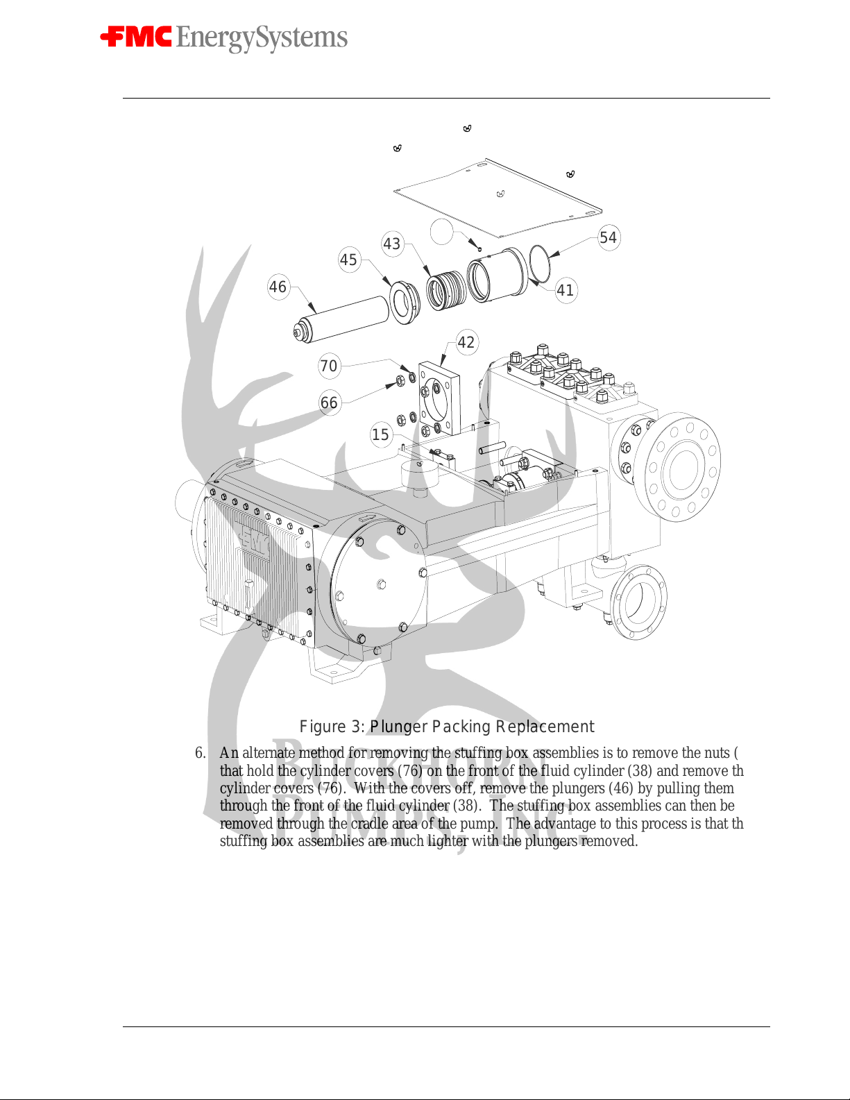
3. Unbolt the plunger clamps (15) and remove them from the plungers (46) and plunger
rods (6). Remove the nuts (66) holding the stuffing box clamps (42) to the fluid cylinder
(38) and remove the stuffing box clamps (42).
4. Rotate the crankshaft by hand until one of the plunger rods (6) is fully retracted from the
plunger (46). Slide the plunger and stuffing box out of the cradle of the pump as a single
unit. Repeat this procedure for the other two plunger stuffing box assemblies.
5. Loosen the set screw (72) locking the threads on the adjusting nut (45) and unscrew the
adjusting nut. Use caution because the packing (43) is spring loaded. Pull the plunger
(46) from the assembly and remove the packing (43).
Doc. No.: OMS500000104
Rev: A Page 20 of 42
Subject to contractual terms and conditions to the contrary, this document and all the information contained herein are the confidential and exclusive
property of FMC Technologies, and may not be reproduced, disclosed, or made public in any manner prior to express written authorization by FMC.
46
45 43
66
70 42
41
72
15
54
Figure 3: Plunger Packing Replacement
6. An alternate method for removing the stuffing box assemblies is to remove the nuts (78)
that hold the cylinder covers (76) on the front of the fluid cylinder (38) and remove the
cylinder covers (76). With the covers off, remove the plungers (46) by pulling them out
through the front of the fluid cylinder (38). The stuffing box assemblies can then be
removed through the cradle area of the pump. The advantage to this process is that the
stuffing box assemblies are much lighter with the plungers removed.
7. Inspect all parts for damage or unusual wear patterns and replace any components that
appear damaged. Insure that the plungers are smooth and free of cracks, scores and
grooves. New packing will fail prematurely if used with plungers that have damaged or
have rough surfaces. FMC recommends that all three packing sets be replaced, not just
those that show signs of leakage, whenever this type of service is performed. This will
help insure maximum operation time between service intervals.
Table of contents
Other FMC Water Pump manuals


Popular Water Pump manuals by other brands

Bestway
Bestway 62055 operating instructions

Gecko
Gecko Aqua-Flo Flo-Master XP3 quick guide

Gardner Denver
Gardner Denver Welch Duoseal 1402C-46 owner's manual

BEST Kiteboarding
BEST Kiteboarding EZ-Pump Instructions for use

Burks
Burks GV Series Installation and operation manual

Masterflex
Masterflex MASTERSENSE MFLX07526-10 operating manual


Wilo
Wilo Medana CH1-L Series Installation and operating instructions

Pfeiffer Vacuum
Pfeiffer Vacuum MVP 015 2 operating instructions

Pfeiffer Vacuum
Pfeiffer Vacuum HENA 202 operating instructions

Hayward
Hayward SUPERPOOL POWPSCP05 owner's manual

Power Craft
Power Craft 79890 instruction manual

Kärcher
Kärcher BTA 5421700 user manual