FMS BMGZ710 User manual

Operating Manual BMGZ710
and BMGZ710.PNET
Robust evaluation unit for conveyor belt scales, with
optional PROFNET interface
Document Version 2.00
Published / Author 04/2021 NS
Firmware Version BMGZ710 0.2.7
Firmware Version BMGZ710.PNET 0.5.4
Diese Bedienungsanleitung ist auch in Deutsch erhältlich.
Bitte kontaktieren Sie Ihre nächstgelegene FMS Vertretung.
© by FMS Force Measuring Systems AG, CH-8154 Oberglatt – All rights reserved.

Operating Manual BMGZ710 and BMGZ710.PNET
20.04.2021 2
1Table of contents
1TABLE OF CONTENTS............................................................................................................................. 2
2SAFETY INSTRUCTIONS.......................................................................................................................... 4
2.1 Representations of safety instructions............................................................................................... 4
2.1.1 Risk that may result in minor or moderate injury........................................................................... 4
2.1.2 Instructions to ensure proper functionality..................................................................................... 4
2.2 General safety instructions................................................................................................................. 4
3PRODUCT INFORMATION........................................................................................................................ 5
3.1 System configuration.......................................................................................................................... 5
3.2 Product description ............................................................................................................................ 5
3.3 Functional description........................................................................................................................ 5
3.4 Scope of delivery................................................................................................................................ 5
3.5 Order code for evaluation unit............................................................................................................ 6
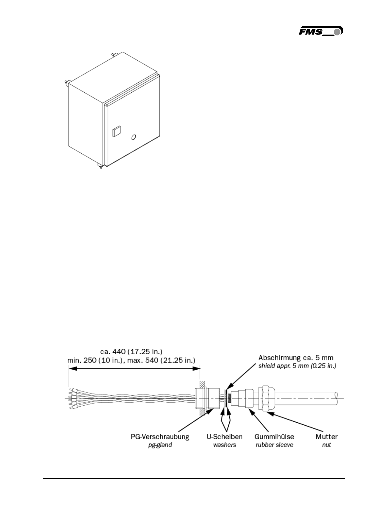
4INSTALLATION.......................................................................................................................................... 7
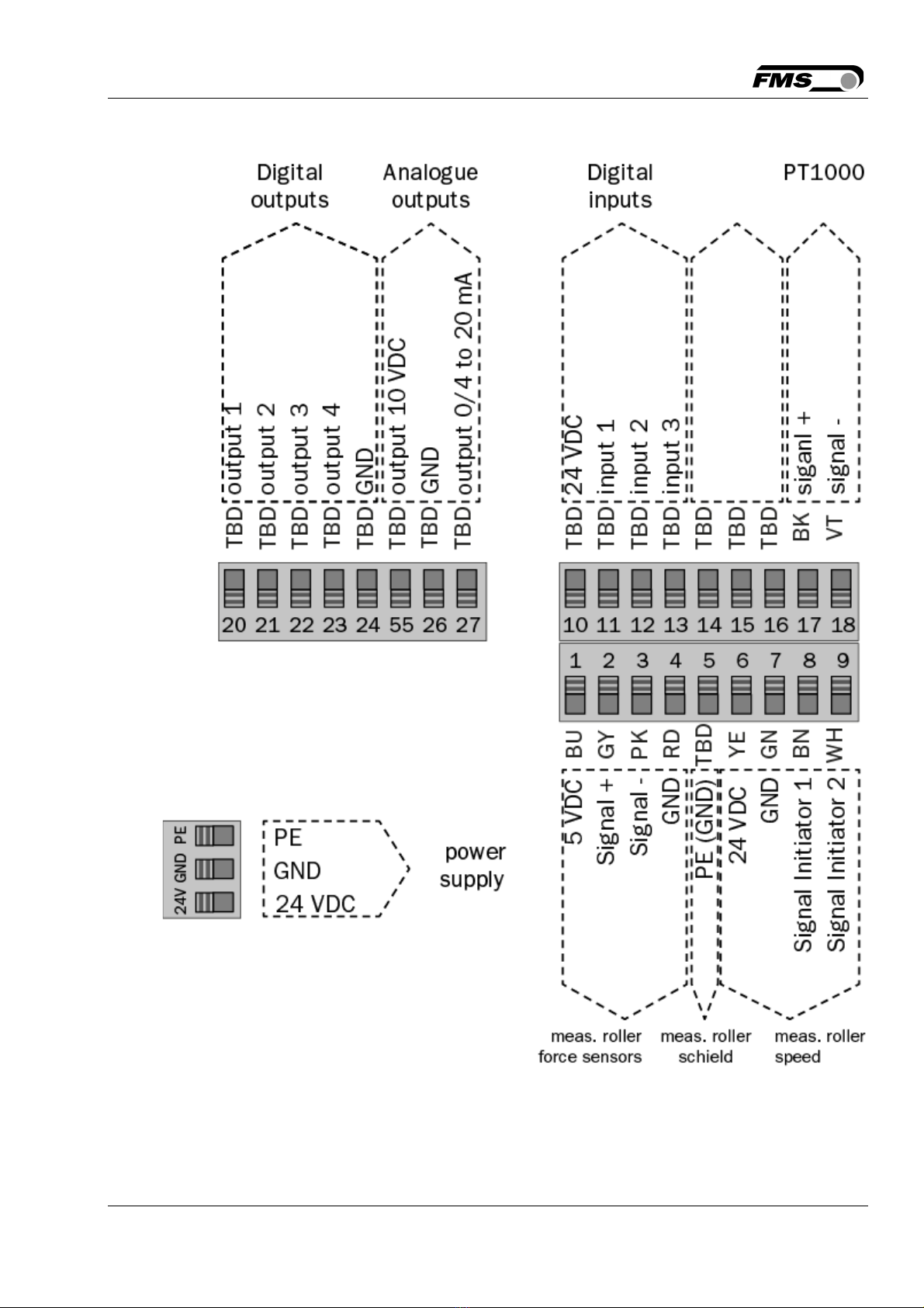
4.1 Electrical connection (see installation instructions for the FMS measuring roller)............................. 8
5OPERATION AND SURFACE................................................................................................................. 11
5.1 Navigation, quick start...................................................................................................................... 11
6CONFIGURATION.................................................................................................................................... 14
6.1 Plant parameters.............................................................................................................................. 14
6.1.1 Description of plant parameters................................................................................................... 14
6.2 Operating parameters...................................................................................................................... 16
6.2.1 Description of operating parameters ........................................................................................... 17
6.3 System parameters.......................................................................................................................... 19
6.3.1 Description of system parameters............................................................................................... 19
6.4 Service ............................................................................................................................................. 21
6.5 Digital inputs..................................................................................................................................... 22
6.5.1 Digital input 1 (zero setting)......................................................................................................... 22
6.5.2 Digital input 2 (batch active) ........................................................................................................ 22
6.5.3 Digital input 3 (belt running)......................................................................................................... 22
6.5.4 Digital input 4 (impulse)............................................................................................................... 22
6.6 Digital outputs .................................................................................................................................. 23
6.6.1 Digital output 1 (BMGZ OK)......................................................................................................... 23
6.6.2 Digital output 2 (taring active)...................................................................................................... 23
6.6.3 Digital output 3 (remote impulse)................................................................................................. 23
6.6.4 Digital output 4 (remote reset)..................................................................................................... 23
7STANDARD PROCEDURES................................................................................................................... 24
7.1 Taring (zero setting)......................................................................................................................... 24
7.2 Calibrating........................................................................................................................................ 25
7.3 Manual batch weighing .................................................................................................................... 26
7.4 Manual batch weighing – with storage in the alibi protocol.............................................................. 26
8CONFIGURATION VIA WEB INTERFACE ............................................................................................. 27
8.1 Peer-to-peer connection................................................................................................................... 27
8.2 Home screen.................................................................................................................................... 30
8.3 Current reading................................................................................................................................ 30
8.4 Parameters....................................................................................................................................... 30
8.5 Alibi protocol..................................................................................................................................... 31
8.6 Ethernet settings.............................................................................................................................. 32
8.7 System settings................................................................................................................................ 32
9DIMENSIONS........................................................................................................................................... 33

Operating Manual BMGZ710 and BMGZ710.PNET
20.04.2021 3
10 TECHNICAL DATA BMGZ710 ................................................................................................................ 36
10.1 Specification PROFINET interface................................................................................................... 36

Operating Manual BMGZ710 and BMGZ710.PNET
20.04.2021
4
2Safety instructions
All safety, operating, and installation instructions given here serve to ensure that the
device functions properly. They must be observed in all circumstances to ensure the
safe operation of systems. Failure to comply with the safety instructions or use of the
devices outside of the specified performance characteristics may endanger the safety
and health of persons.
Work relating to the operation, maintenance, conversion, repair, or configuration of the
device described may only be performed by qualified personnel.
2.1 Representations of safety instructions
2.1.1 Risk that may result in minor or moderate injury
Danger, warning, caution
Type and source of danger
Possible consequence of disregarding the instruction
Measures to prevent the danger
2.1.2 Instructions to ensure proper functionality
Instruction
Instruction regarding proper operation
Simplification of operation
Ensuring functionality
2.2 General safety instructions
The functionality of the conveyor belt scales is only guaranteed if the
components are installed in the recommended configuration. If not,
there is a risk of serious malfunction. The installation instructions on
the following pages must therefore always be followed.
The on
-
site installation regulations serve to ensure the safety of
electrical systems. These regulations are not taken into
consideration by this operating manual. However, they must always
be observed nonetheless.
Improper earthing may cause electric shocks to people, malfunctions
of the entire system, or damage to the evaluation unit! It must
always be ensured that the housing is properly grounded.

Operating Manual BMGZ710 and BMGZ710.PNET
20.04.2021 5
3Product information
3.1 System configuration
Illustration 1: Measuring roller and evaluation unit BMGZ700_BA_Manual.ai
3.2 Product description
The evaluation units in the BMGZ700 series are designed to meet the demanding
conditions of applications in mobile and stationary conveyor systems. The illuminated
graphical display shows the current flow rate, the daily amount, the total amount, and
the belt speed. Additional display devices and controls can be connected via the
configurable analogue and digital outputs. The web browser, included by default, allows
the measuring roller to be quickly configured, e.g. with any PC or laptop, or by remote
access.
An integrated PROFINET interface is available as option.
3.3 Functional description
The evaluation units in the BMGZ700 series convert the measuring signals from the
measuring roller into digital form. The weight of the measuring roller and the load from
the belt (taring) are subtracted from the measured value, and the resulting difference is
multiplied with the belt speed. The evaluation units in the BMGZ700 series have an
auto-taring program that automatically determines the tare value over two belt
revolutions by pressing a button.
3.4 Scope of delivery
Included in the delivery:

Operating Manual BMGZ710 and BMGZ710.PNET
20.04.2021 6
Evaluation unit; for the .K version, the evaluation unit is preinstalled in the control
cabinet
Not included in the delivery:
Power supply unit, installation materials
Also available:
Measuring roller, connection cable from evaluation unit to measuring roller (specify
length), M12 d-coded Ethernet cable, or RJ45 patch cable for web browser.
3.5 Order code for evaluation unit
Illustration 2: Order code for evaluation unit BMGZ700_Datenblatt.indd

Operating Manual BMGZ710 and BMGZ710.PNET
20.04.2021 7
4Installation
Several versions of the evaluation unit are available.
Illustration 3: BMGZ710.W Wall mount BMGZ700_BA_Manual.ai
-Unscrew the 4 screws on the cover with the membrane control panel and display
-The cover can now be opened
-The housing is screwed on through the 4 holes in the bottom of the housing
Illustration 4: BMGZ710.S Panel mount BMGZ700_BA_Manual.ai
-The panel must be prepared with a suitable recess and holes. See dimensions
-The housing is screwed on with the sheet through the 4 holes

Operating Manual BMGZ710 and BMGZ710.PNET
20.04.2021 8
Illustration 5: BMGZ710.K Cabinet BMGZ700_BA_Manual.ai
-The cabinet is screwed on through the 4 holes in the back wall
-Use the rubber mounts if the system experiences vibrations
4.1 Electrical connection (see installation instructions for the FMS
measuring roller)
The connection between the measuring roller and the evaluation unit must use the 8-
core twisted-pair cable (min. 4x2x0.75 mm2) provided.
The cable must be laid away from any power cables to ensure that no interference is
induced in the measurement signal. On the measuring roller side, remove the plastic
sheath of the cable over a length of approx. 14 cm.
The white wire is not required. Connect the shield to terminal 5.
On the evaluation unit side, remove the plastic sheath over a length of a approx. 25-54
cm. The white wire is not required.
The cable shield must be connected on both sides.
For the K version of the housing (cabinet), feed the cable with the 8-pin plug through the
cabinet wall.
Illustration 6: Connection cable, evaluation unit side
BMGZ700_BA_Manual.ai

Operating Manual BMGZ710 and BMGZ710.PNET
20.04.2021 9
Illustration 7: Terminal assignment BMGZ710 BMGZ700_BA_Manual.ai

Operating Manual BMGZ710 and BMGZ710.PNET
20.04.2021 10
Illustration 8: Connection cable, measuring roller side BMGZ700_BA_Manual.ai

Operating Manual BMGZ710 and BMGZ710.PNET
20.04.2021 11
5Operation and surface
Illustration 9: View of device BMGZ700_BA_Manual.ai
The assignment of the softkeys may vary. The saved functions are shown on the display.
5.1 Navigation, quick start
The menu is divided into two levels
To navigate between levels, use the softkeys (menu) or
Level 1: HOME
Display current system data with different representations
Level 2: CONFIGURATION
Plant parameters – One-time set-up of conveyor belt and measuring roller
System parameters – Country-specific parameters
Operating parameters – One-time configuration, inputs and outputs
Calibration – Input correction factor
Alibi protocol – Fail-safe storage of batch data
Service – Access to system status and detailed display of error messages
Use the navigation keys to select individual parameters
To make a selection, press

Operating Manual BMGZ710 and BMGZ710.PNET
20.04.2021 12
Levels, navigation
Levels Navigation Display
HOME
Home
Histogram
Zero setting
Batch

Operating Manual BMGZ710 and BMGZ710.PNET
20.04.2021 13
Detail
CONFIGURATION
PARAMETER

Operating Manual BMGZ710 and BMGZ710.PNET
20.04.2021 14
6Configuration
6.1 Plant parameters
The plant parameters directly affect the weighing results.
Plant parameters
Parameter Unit Selection Default Min. Max. No.
Offset [Digit] 0
-
32768 32767 1
Gain [
-
] 1 0.1 10 2
Belt length [m] 10 1 5000 3
Diameter [mm] 108 10 1000 4
Pulse [
-
] 4 1 100 5
Distance [mm] 2000 100 5000 6
Nominal force [N] 1000 1 5000 7
Table 1: Plant parameters
6.1.1 Description of plant parameters
Parameter
Name Description
Offset The evaluation unit saves the value determined during taring /
zero setting in [Digit].
If the electronics unit is replaced, the values determined by the
previous unit can also be entered manually here.
Unit Digit
Min. -32768
Max. 32768
Default 0
Increment 1
Gain The value determined during calibration is saved under this
parameter. If the automatic calibration cannot be used, a
manually determined value can also be entered here.
Unit -
Min. 0.100
Max. 10.000
Default 1.000
Increment 0.001

Operating Manual BMGZ710 and BMGZ710.PNET
20.04.2021 15
Parameter
Name Description
Belt length The unrolled length of the conveyor belt is saved under this
parameter. This value is required for taring.
Unit m
Min. 1
Max. 5000
Default 10
Increment 1
Diameter The diameter of the centre roller is saved under this parameter
(see measuring roller nameplate).
Unit mm
Min. 10
Max. 1000
Default 108
Increment 1
Pulse The number of blades of the pulse generator is stored under
this parameter, see measuring roller nameplate. This value
corresponds to the number of pulses per revolution of the
measuring roller.
Unit -
Min. 1
Max. 100
Default 4
Increment 1
Distance The distance between adjacent idlers is saved under this
parameter. This value corresponds to the sum of the distances
between the measuring roller and the preceding and following
idler stations.
Unit mm
Min. 100
Max. 5000
Default 2000
Increment 1

Operating Manual BMGZ710 and BMGZ710.PNET
20.04.2021 16
Parameter
Name Description
Nominal force Nominal force of the force senors. This value is indicated on
the label of the measuring roller and the labels of each force
sensor.
See measuring roller nameplate.
Unit N
Min. 1
Max. 5000
Default 1000
Increment 1
Table 2: Description of plant parameters
6.2 Operating parameters
Operating parameters
Parameter Unit Selection Default Min. Max. No.
Pulse output [kg] 1, 10, 100,
1000
100 50
Current output 0 to 20; 4 to
20 mA
4 to 20 mA 51
Filter output [Hz] 10.0 0.1 20.0 52
Scaling [t/h] 1000.0 1.0 5000.0 53
Max. Q [t/h] 0 1 5000 54
v
-
detection
-
auto, none auto 55
Table 3: Operating parameters

Operating Manual BMGZ710 and BMGZ710.PNET
20.04.2021 17
6.2.1 Description of operating parameters
Operating parameters
Name Description
Pulse output The pulse output of the BMGZ700 emits a pulse after a certain
integrated weight has been exceeded. The weight
corresponding to one pulse is stored under this parameter.
Pulse duration 12 ms, max. 40 / sec.
Unit kg
Selection 1, 10, 100, 1000
Default 100
Increment 1
Current output Two proportional analogue outputs are available for the flow
rate.
The voltage output sends a signal from 0 to 10 V.
The type of current output signal is selected here.
Current and voltage outputs can be used independently.
Unit -
Selection 0 to 20 mA, 4 to 20 mA
Default 4 to 20 mA
Filter output First
-
order low
-
pass filter for the analogue output to filter out
undesirable fluctuations.
The threshold frequency is configured here.
This filter is independent of the other filters.
Unit Hz
Min. 0.1
Max. 20.0
Default 10.0
Increment 0.1

Operating Manual BMGZ710 and BMGZ710.PNET
20.04.2021 18
Operating parameters
Name Description
Scaling output Here, you can define the flow rate that generates the
maximum output signal (10 V or 20 mA) at the analogue
outputs.
The resolution is 12 bits.
Unit t/h
Min. 1.0
Max. 5000.0
Default 1000.0
Increment 0.1
Max. Q The maximum flow rate Q of the conveyor belt scales is saved
under this parameter. If the flow rate falls below 5% of this
parameter, the counters stop integrating. The measurement
is stopped, and an error is displayed.
Unit t/h
Min. 0
Max. 5000
Default 0
Increment 1
v
-
detection If this parameter is set to “automatic”, the speed of the
conveyor belt is recorded with the pulse generator integrated
into the measuring roller.
If the parameter is set to “none”, no speed detection is
performed. The flow rate is then calculated with a fixed speed
of 1.00 m/s.
The digital input “belt running” is used to determine whether
the belt is stopped or running.
Unit -
Selection none
automatic
Default none
Table 4: Description of operating parameters

Operating Manual BMGZ710 and BMGZ710.PNET
20.04.2021 19
6.3 System parameters
System parameters
Parameter Unit Selection Default Min. Max. No.
Language
-
German,
English
German 1
Filter display Hz 1.0 0.1 1.0 2
Date format
-
DD.MM.Y
YYY,
MM.DD.Y
YYY
DD.MM.YYYY 3
Time / date
-
00:00
01.01.202
0
23:59
31.12.2099
4
IP address
-
192.168.0.90 0 255 5
Subnet mask
-
255.255.255.0 0 255 6
Table 5: System parameters
6.3.1 Description of system parameters
System parameters
Name Description
Language This parameter allows the display language to be selected.
Either German or English can be selected.
Unit -
Selection German, English
Default German
Filter display First
-
order low
-
pass filter to filter out undesirable fluctuations
from the display. The threshold frequency of the filter is
configured here.
Unit Hz
Min. 0.1
Max. 10
Default 1.0
Increment 0.1
Date format Here, the format of the displayed date can be configured.
Unit -
Default DD.MM.YYYY
Increment DD.MM.YYYY, MM.DD.YYYY

Operating Manual BMGZ710 and BMGZ710.PNET
20.04.2021 20
System parameters
Name Description
Time / date The evaluation unit has a built
-
in real
-
time clock (RTC). To
configure the time, the current time and date can be entered
into this parameter.
This information is stored in the alibi memory with the
corresponding batch.
There is NO automatic compensation of summer and winter
time
Unit -
Min. 00:00 01.01.2020
Max. 23:59 31.12.2099
IP address Static IP address of the evaluation unit
The IP address is entered in four blocks.
Unit -
Min. 0
Max. 255
Default 192.168.0.90
Subnet mask The subnet mask is entered in four blocks.
Unit -
Min. 0
Max. 255
Default 255.255.255.0
Table 6: Description of system parameters
This manual suits for next models
1
Table of contents