FNGi DHCPatriot Version 6 User manual

Operations Manual
Version 6


Table of Contents
Chapter 1: Requirements!9
Network and Router Requirements!9
Optional External Equipment!9
Power and Cabling Requirements!9
Chapter 2: Network Integration and Example!11
Device Placement!11
Authenticated DHCP Installation Example!11
Example External Device Configuration for Authenticated DHCP!12
Chapter 3: Installation!14
Installing the Hardware!14
Unpacking the system!14
Mounting in a two or four post rack!15
Attaching Cables!16
Chapter 4: Initial Configuration!17
Menu Interface!17
Serial Console Access!17
Console from AUX on a Cisco®!17
Console from an OCTAL cable connected to an ASYNC port!18
Console from a serial (DB9) port on a standard PC!18
Secure Shell (SSH) Access!19
Configuring the Menu Interface!20
Changing the ‘admin’ user password!20
IP Address Configuration!20
IPv6 Address Configuration (Optional)!21
Domain Name Configuration!21
Ethernet Media Settings (Speed and Duplex)!22
Configuring the Firewall for the Administration Network!22
Initial Configuration Reboot!23
Web Administration Interface Account Setup!24
Web Administration Interface!25
Tab le o f C on te n ts
3
DHCPatriot Version 6 Operations Manual This document © 2017 First Network Group Inc. All Rights Reserved

Connecting to the Web Administration Interface!25
Configuring the General Settings in General Setup !26
Chapter 5: General Tasks!28
Administrative User Maintenance!28
Built-in Firewall Configuration!29
IPv6 Built-in Firewall Configuration!29
System Logs!30
Changing Your Password!31
Set App Permissions!31
Chapter 6: Authenticated DHCP!32
Configuring Authenticated DHCP!32
Authentication Servers!32
Internal (Built-in Authentication)!33
External!33
Captive Portal!33
Adding!34
Editing!35
Removal!35
Shared Network Configuration!35
Shared Network!35
Adding!36
Editing!36
Removal!36
Unauthenticated Subnet!37
Adding!37
Editing!37
Disable!37
Removal!38
Authenticated Subnet!38
Adding!38
Editing!38
Disable!38
Removal!39
Tab le o f C on te n ts
4
DHCPatriot Version 6 Operations Manual This document © 2017 First Network Group Inc. All Rights Reserved

Static Subnet!39
Adding!39
Editing!39
Removal!39
Maintenance Subnet!40
Adding!40
Editing!40
Removal!40
Special Reports!40
View Authenticated Users!41
Users Using Multiple IPs!41
Chapter 7: Standard DHCP!42
Shared Network Configuration!42
Shared Network!42
Adding!43
Editing!43
Removal!43
Dynamic Subnet!43
Adding!44
Editing!44
Disable!44
Removal!44
Static Subnet!44
Adding!45
Editing!45
Removal!45
Maintenance Subnet!45
Adding!46
Editing!46
Removal!46
Additional Configuration Tasks!46
Known Client!46
Adding!47
Tab le o f C on te n ts
5
DHCPatriot Version 6 Operations Manual This document © 2017 First Network Group Inc. All Rights Reserved

Editing!47
Removal!47
Static IP Assignment!47
Adding!47
Editing!48
Removal!48
TFTP File Maintenance!48
Adding!49
Mass Change of TFTP File Assignments!49
Editing!49
Removal!49
Chapter 8: Common Authenticated and Standard DHCP Actions and
Reports!50
Sticky IP Address!50
Adding!50
Editing!50
Removal!51
Exclude IP Address!51
Adding!51
Removal!51
Deny Mac Address!52
View Address Usage!52
Search Sessions!53
Possible hijacked IP Addresses!55
Chapter 9: DHCPv6 Configuration and Maintenance!56
IPv6 Primer!56
DHCPv6 Primer!57
Configuration and Maintenance of DHCPv6 on the DHCPatriot!59
Chapter 10: Monitoring and Graphing the System!64
Allowing Subnets to Monitor the DHCPatriot!64
Monitoring Critical Services and Their Importance!65
Graphing System Performance!68
Tab le o f C on te n ts
6
DHCPatriot Version 6 Operations Manual This document © 2017 First Network Group Inc. All Rights Reserved

Graphing Address Utilization!70
Miscellaneous SNMP Information!73
Server Status on the Web Administration Interface!73
Chapter 11: Remote Access API!75
Setting up the User for API Access!75
User Access!75
Authenticate Device!76
Suspend Device!76
Mass Suspend Device by Username!77
Enable Device!78
Search Authenticated Devices!78
Sticky IP Add!79
Sticky IP Delete!79
Sticky IP List!80
Built-in Authentication!80
List Customers!80
Add Customer!81
Edit Customer!81
Suspend Customer!82
Enable Customer!82
Delete Customer!83
Change Password!83
Deny MAC Address!83
Add Denied MAC Address!83
Remove Denied MAC address!84
Remote Search!84
Get Network Config!86
Standard DHCP!87
List Known Client!87
Add Known Client!87
Edit Known Client!88
Delete Known Client!88
List Static IP Assignments!89
Tab le o f C on te n ts
7
DHCPatriot Version 6 Operations Manual This document © 2017 First Network Group Inc. All Rights Reserved

Add Static IP Assignment!89
Edit Static IP Assignment!90
Delete Static IP Assignment!90
Chapter 12: Supporting DHCPatriot End-Users!91
How to Troubleshoot!91
Authenticated DHCP!91
Authorize Customer!91
Standard DHCP!92
Search DHCP Logs!92
General Troubleshooting Techniques!93
Authentication Problems!95
Chapter 13: User Based Tasks for Customer Service!97
Suspend User!97
Built-in Authentication: User Maintenance!98
Adding a User!98
Editing a User!99
Suspending One or More Users / Enabling suspended users!99
Deleting a User!100
Mass Delete of Suspended Users!100
Built-in Authentication: User Import!100
Device Import!101
Tab le o f C on te n ts
8
DHCPatriot Version 6 Operations Manual This document © 2017 First Network Group Inc. All Rights Reserved

Chapter 1: Requirements
Network and Router Requirements
The customers must use DHCP (see rfc1542 - http://www.faqs.org/rfcs/rfc1542.html) to
obtain their dynamic IP Address. The DHCPatriot system does not support other
broadband authentication protocols such as PPPoE.
The gateway routers that the customers are connected to must support the DHCP
Relay Agent protocol (see “BOOTP Relay Agent” rfc1542 Section 4 - http://
www.faqs.org/rfcs/rfc1542.html) (Cisco® defines this as the ‘ip helper-address’
command). This is important as the DHCPatriot system cannot exist on the same
physical LAN as the customers. It expects to be separated from the customers and
interact with a DHCP Relay Agent. Further, the device’s DHCP Relay Agent protocol
implementation must support DHCP Failover (see http://tools.ietf.org/html/draft-ietf-dhc-
failover-07) (Cisco® devices that support ‘ip helper-address’ support DHCP Failover
without special modification).
The DHCPatriot system must NOT be located in a separately uplinked network from the
customer network. For example, if you have a remote POP (Point-Of-Presence) that is
not directly linked to your network, but which, instead, uses some other backbone
provider to link the customers to the Internet, then a single DHCPatriot system cannot
be used centrally in this situation. An additional system will be needed for that separate
pop. In other words, the customer traffic must not leave your routing control before
arriving at the DHCPatriot system. If this is not the case, then the policy based routing
will not work for the optional authentication.
Some routers in the network will need to support policy based routing. Most Cisco®
routers and layer 3 switches support policy based routing in order for the optional
authentication to function.
Optional External Equipment
The DHCPatriot system may use either the Built-in Authentication, or an optional
external RADIUS server for authentication and accounting of customers. It must use
one method or the other. Note: The RADIUS server must at least respond with the
Framed-IP-Address attribute set to 255.255.255.254.
Power and Cabling Requirements
**PLEASE NOTE: This section applies to only AC powered DHCPatriot systems. DC
powered systems use 48 volt DC.**
Each DHCPatriot device has a single power supply. This power supply is AC
(Alternating Current) compatible only. DO NOT plug the devices into DC (Direct
Chapter 1: Requirements
9
DHCPatriot Version 6 Operations Manual This document © 2017 First Network Group Inc. All Rights Reserved

Current) power as property damage, serious injury, or death may result! The power
supply has an auto-switching capability. It will automatically sense 100-110v or 240v
and may be used with those currents. The input rating on the power supply is 100-240v
60-50Hz 5-3A. This power supply should work in any region that standard computer
equipment functions in. If unsure, please consult with a local electrician. First Network
Group cannot be held responsible for any damages, injury or loss of life that result from
improper power delivery. Note that there is now a DC (Direct Current) version available.
The following cables and accessories will be required to complete your installation:
Two power cables (included). Note: The DHCPatriot system ships with power cables
suitable for plugging into an American 120v 60 Hz outlet. A different cable may be
needed in your region. The power supply will accept a standard PC cable from your
region. Please note that if the DC version is purchased it will not come with power
cabling.
Two serial console adapters (included) (optional). Two console cables (not included) for
connection of the console ports on the DHCPatriot devices to a customers supplied
console server.
One gigabit 1-foot crossover Ethernet cable (included).
Two standard 100 megabit (category 5) or gigabit (category 5e or 6) Ethernet cables
(not included) for connection to customer supplied Ethernet switch. Cables should be
chosen that match the expected speed of the link. The DHCPatriot devices support
10baseT, 100baseT and 1000baseT in either half or full duplex (full duplex mode is
recommended). If the devices are to be plugged into a gigabit switch (hubs are not
recommended), then a gigabit Ethernet cable should be used.
Chapter 1: Requirements
10
DHCPatriot Version 6 Operations Manual This document © 2017 First Network Group Inc. All Rights Reserved
Chapter 2: Network Integration and Example
The DHCPatriot system can replace any existing DHCP server that you may have in
your network. It can force authentication of customer equipment using either the Built-in
Authentication server or an external RADIUS server. The system may optionally
interact with an external RADIUS server.
Device Placement
The DHCPatriot system is designed to be placed in the server farm in the core of your
network. It supports centrally serving customers in your network. Placement at the
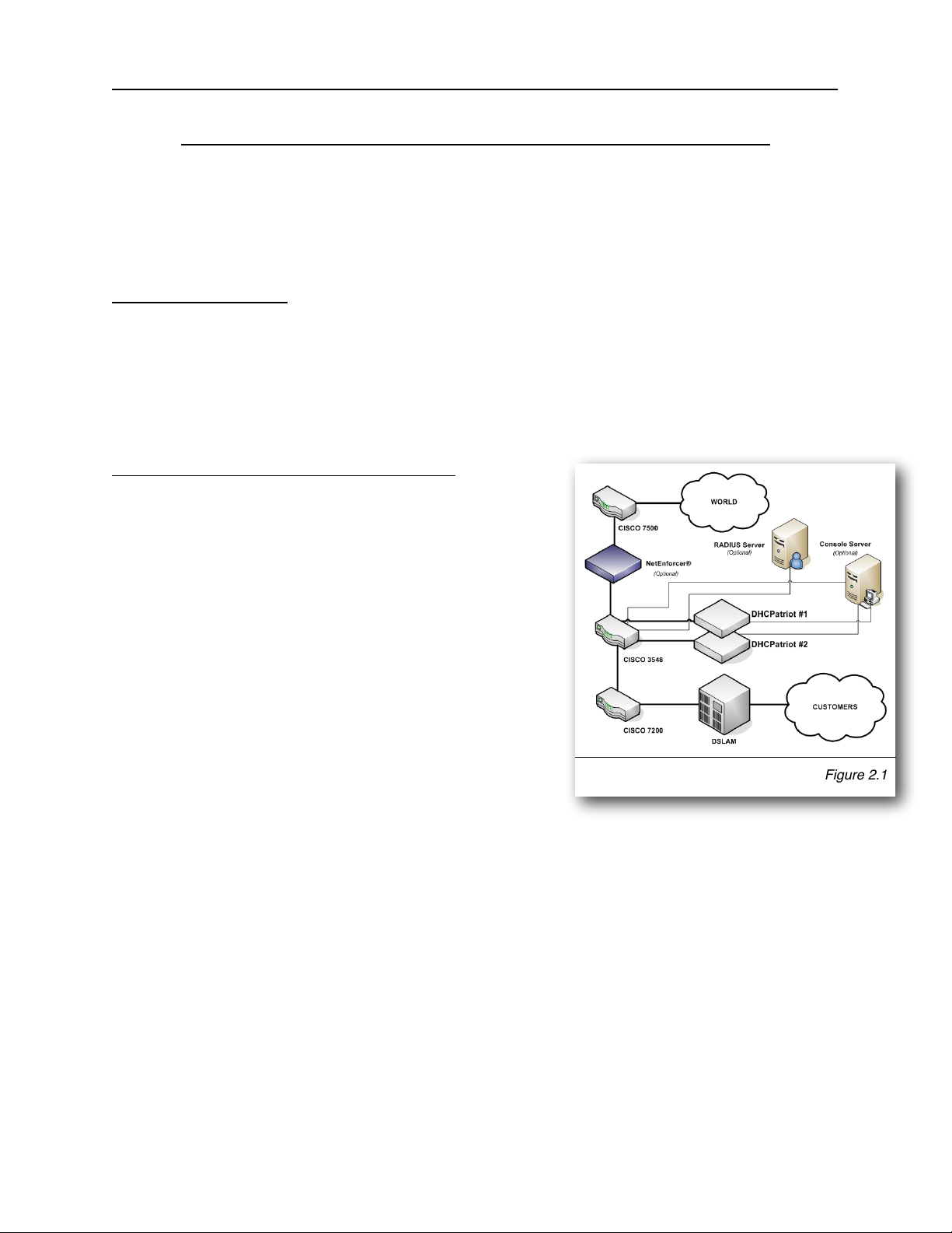
core is not strictly required, however. Figure 2.1 shows placement in a typical network.
An example of usage follows. This example will help in the decision regarding
placement in your network.
Authenticated DHCP Installation Example
In figure 2.1, the optional RADIUS server and console
server are shown. Using the example in figure 2.1,
we can construct a proper setup for the DHCPatriot
system. This will help you understand how the
DHCPatriot will integrate into your network.
This example network consists of a simple border,
server farm and customer network that consists of
Ethernet based DSL. For the purposes of this
example, we will assume that the DSLAM is providing
only bridging services, not routing. On the Cisco®
7200, the Ethernet from the DSLAM terminates on
fastethernet 0/1 and the Ethernet link from the
Cisco® 3548 to the Cisco® 7200 terminates on
fastethernet 0/0 on the Cisco® 7200. VLAN 3 exists
between the Cisco® 3548 and the Cisco® 7200. VLAN 2 exists between the Cisco®
3548 and the server farm which contains the DHCPatriot system, the optional RADIUS
server and the optional console server. VLAN 1 exists between the Cisco® 3548 and
the Cisco® 7500 border router.
To better understand how the system functions, it is necessary to describe it from the
perspective of a new customer device on the network.
Since this is a new device, the MAC Address is unknown to the DHCPatriot system.
The system will force the device to be authenticated before being allowed on to the
network (optional). The customer turns the device on. It is configured for DHCP and
therefore requests an IP Address. The Cisco® 7200 router, acting as a DHCP Relay
Chapter 2: Network Integration and Example
11
DHCPatriot Version 6 Operations Manual This document © 2017 First Network Group Inc. All Rights Reserved
Figure 2.1

agent, forwards this request to the system. The DHCPatriot system responds with an
IP Address out of the unauthenticated network.
For the device to receive an authenticated IP Address, the customer must first
authenticate the device. The customer opens a web browser on the device in an
attempt to begin using the network. The Cisco® 3548 forwards all traffic to the
DHCPatriot system due to the source IP address originating in the unauthenticated
network. The system responds by sending the device the authentication page. The
customer types his username and password, and the device posts this to the
DHCPatriot system. The system contacts the optional RADIUS server (or itself in the
case of using Built-in authentication) for authorization. The optional RADIUS server
responds with Access-Accept. The system adds the device to its database of known
devices and responds to it with a thank you page stating that the device must be
rebooted. The customer reads this page and then reboots the device. The device will
not receive an unauthenticated address again, unless it is suspended on the
DHCPatriot system.
Upon booting up, the device requests an IP Address from the DHCPatriot system again.
At this time, the Cisco® 7200 again forwards the request to the system which responds
with an authenticated address. The system will authenticate the device with the
optional RADIUS server. The optional RADIUS server will again respond with Access-
Accept. The DHCPatriot system marks the device as being online in its database, and
sends an accounting start to the optional RADIUS server. The device is now able to
access the Internet.
Some time passes and the customer shuts the device down. After the lease period
expires, the DHCPatriot system will mark the device as being offline, and send an
accounting stop to the optional RADIUS server.
Example External Device Configuration for Authenticated DHCP
Some configuration changes on external devices to the DHCPatriot system are required
to support the example. On the Cisco® 7200 fastethernet 0/1, the ip helper-address
command would be added as well as the gateway address of both the authenticated
network, as well as the unauthenticated network that the customers will be using:
ip address <Customer gateway address (Authenticated)> <netmask>
ip address <Customer gateway address (Unauthenticated)> <netmask> secondary
ip helper-address <DHCPatriot primary device IP>
ip helper-address <DHCPatriot secondary device IP>
On the Cisco® 3548, the policy routing is needed on VLAN 3. This policy routing is
used to force unauthenticated customer’s outbound traffic to the DHCPatriot system for
forced authentication purposes. The Cisco® 3548 will require two configuration
changes to accommodate this setup. First, in the global configuration area:
Chapter 2: Network Integration and Example
12
DHCPatriot Version 6 Operations Manual This document © 2017 First Network Group Inc. All Rights Reserved

access-list <#> permit ip <Unauthenticated Wire Address> <Reverse Mask> any
access-list <#> deny ip any any
!
route-map <route map name> permit 10
match ip address <access-list #>
set ip next-hop <ip of DHCPatriot primary device>
!
Second, applied to VLAN 3:
ip policy route-map <route map name>
Additionally, some configurations are needed on optional devices to support the
example. The optional RADIUS server must be configured to allow each DHCPatriot
device to connect as a RADIUS client.
Although not described in this example, the optional console server may be used in this
example network allowing connection to the DHCPatriot for some administrative tasks.
Please note that as of 5.3.0 it is possible to configure a third IP address that “floats”
between the two devices via VRRP, a floating IP address if you will. This is configured
in the web administration interface under General Setup which will be covered later in
the manual. It is now recommended that this floating IP address be configured and
used in place of the ip of DHCPatriot primary device in the above example.
Chapter 2: Network Integration and Example
13
DHCPatriot Version 6 Operations Manual This document © 2017 First Network Group Inc. All Rights Reserved
Chapter 3: Installation
Installing the Hardware
This chapter describes the
procedures necessary to
physically install your
DHCPatriot system in the
Telco rack, connect cables to
the devices and properly
configure the console server
for access to the DHCPatriot
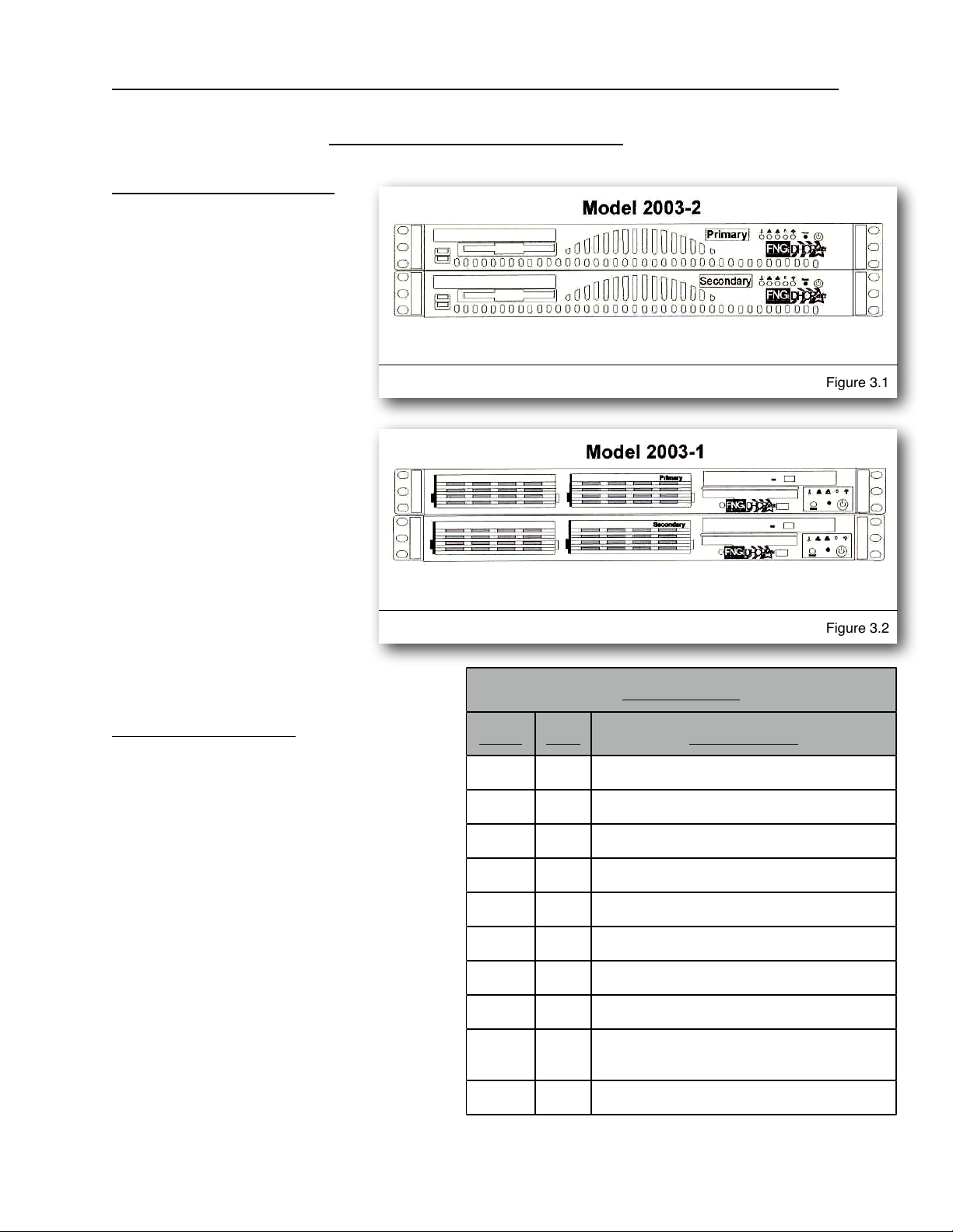
devices. This manual covers
only model 2003-2 and
greater DHCPatriot systems.
Figure 3.1 shows model
2003-2 and greater. If you
have the older system, model
2003-1 (see figure 3.2),
please use the original
manual provided with the
DHCPatriot system for
physical installation, or
contact First Network Group
for physical installation
instructions.
Unpacking the system
You should inspect the box and make
note of any damage. If either
DHCPatriot device shows any damage
notify First Network Group immediately.
Packed in the boxes are all the parts
you should need to mount your server in
a telco or server rack.
In addition to the parts listed in the
packing list above, the customer will
need to supply the following items:
•Rack Screws - Screws and
washers to attach the DHCPatriot
devices to your telco or server
rack.
Chapter 3: Installation
14
DHCPatriot Version 6 Operations Manual This document © 2017 First Network Group Inc. All Rights Reserved
Figure 3.1
Figure 3.2
Packing List
Packing List
Packing List
Item
Qty
Description
1
2
DHCPatriot units (1 primary, 1 secondary)
2
2
DB9 to RJ45 adapter (serial console adapter)
3
2
Power Cable
4
1
Red Crossover Cable
5
1
DHCPatriot Manual (this document)
6
1
EULA (End User License Agreement)
7
1
Maintenance Contract Quick List
8
1
Maintenance Contract
9
1
IP/Hostname Notice (regarding Maintenance
Contract activation)
10
1
Return Policy Statement

•Ethernet Cables - Two standard Ethernet cables of sufficient length to attach the
DHCPatriot devices to the Ethernet switch.
•Console Cables (optional) - Two cables suitable for the console connection. We
will cover the optional console connection in more detail later.
Mounting in a two or four post rack
The DHCPatriot system may be mounted in a two post or a four post 19” telco or server
rack. This section describes mounting in a two or four post rack.
The installation steps should be
read in their entirety before
installation is started. All parts
should be unpacked, inspected
for damage and checked for
completeness before continuing
with set up. A suitable location
for installation will have a clean,
dust free environment that is
well ventilated. Do not set up
your DHCPatriot system in an
area where heat, electrical
noise, or electromagnetic fields
are generated. The area
chosen must have close access
to a grounded AC power outlet.
The location chosen should be
climate controlled with a
temperature range of 10° to 35°
C (50° to 90° F). Relative
humidity should be in the range
of 8% to 90%. Damage not
covered by the maintenance
contract may result if the
DHCPatriot system is operated
outside of this temperature or
humidity range.
When choosing a location in the rack in which to place the devices, be sure that proper
clearance is available in both the front and back. Front clearance should be no less
than 25 inches, and rear clearance should be no less than 30 inches. This ensures
proper airflow and cooling around the devices.
Chapter 3: Installation
15
DHCPatriot Version 6 Operations Manual This document © 2017 First Network Group Inc. All Rights Reserved
Figure 3.3

Each device is installed by using the customer supplied rack mounting screws. Two
screws on each side will secure a DHCPatriot device to the rack (see figure 3.3). If it is
installed in a four post rack, the back two posts will not be used.
Important! Take great care when installing the devices in the rack. Two people should
be involved in the installation. One person should hold the device in the rack, while the
other one inserts the screws. Be sure each device is secure in the rack. Damage not
covered by the maintenance contract may occur if a device is dropped, or falls out of the
rack.
Attaching Cables
The power cables supplied with the
DHCPatriot system may be used in many
locations. A standard PC power cable
from your region may be required. Plug a
power cable from the standard PC 3
prong outlet on each device. Plug the
other end of the power cable into an AC
power outlet with the proper
specifications. The red crossover cable
(supplied) is used to connect the devices
to each other. Connect the cable to the
ports on each unit as shown in figure 3.4.
The two DB9 to RJ45 serial console
adapters (supplied) are connected to the
serial port of each device as shown in
figure 3.4. Install the adapters even if you
do not intend to use the serial console
capabilities.
The LAN port is used to connect the
DHCPatriot system to the Ethernet
switch. The customer supplied Ethernet
cable should be used for this connection.
A console cable may optionally be
connected from the female RJ45 end of
each DB9 to RJ45 adapter that are
installed in the serial port on the back of
each device to the console server.
Chapter 3: Installation
16
DHCPatriot Version 6 Operations Manual This document © 2017 First Network Group Inc. All Rights Reserved
Figure 3.4
Note that as of hardware model 2013-1,
the ports are now reversed. The
Backup port is now closest to the VGA
port and the LAN1 port is now furthest
from the VGA port.

Chapter 4: Initial Configuration
The DHCPatriot system has two stages of initial configuration. First the menu interface
must be accessed via serial console or SSH (Secure Shell). During this configuration
such things as IP Address, domain name and web administration interface users are
configured. After this, then the General settings must be set on the Web administration
interface. The DHCPatriot system is then ready to use and can be configured for
DHCP etc...
Menu Interface
The menu interface is the first stage of configuration. This is accessed via SSH or serial
console. The username ‘admin’ with the password ‘cU$0gNn1’ is used to login to the
interface.
Serial Console Access
The DHCPatriot system allows
console access to the devices
via a standard PC style DB9
male serial port. A female DB9
to female RJ45 serial console
adapter is provided. This
adapter is well suited to access
from most Cisco® compatible
console servers. These
devices are also compatible
with Cisco® console
implementation and standard
PC (UNIX based OSs,
Microsoft® Windows® and
Apple® Mac® systems)
implementations. The pin
assignment of the serial port
and RJ45 port are supplied for
use in other situations.
Console from AUX on a Cisco®
Plug one end of a Cisco® ‘flat
black’ cable into the desired AUX port on the Cisco® router. Plug the other end of a
Cisco® ‘flat black’ cable into the Female RJ45 on the console shell attached to the
desired DHCPatriot device. Configure the AUX port thus for console access:
Chapter 4: Initial Configuration
17
DHCPatriot Version 6 Operations Manual This document © 2017 First Network Group Inc. All Rights Reserved
Serial Port Pin Out
Serial Port Pin Out
Serial Port Pin Out
Serial Port Pin Out
PIn #
Definition
Pin #
Definition
1
CD (Carrier Detect)
6
DSR (Data Set Ready)
2
RxD (Receive Data)
7
RTS (Request To Send)
3
TxD (Transmit Data)
8
CTS (Clear To Send)
4
DTR (Data Terminal Ready)
9
RI (Ring Indicator)
5
GND (Ground)
Serial Console Adapter Female RJ45 Pin Out
Serial Console Adapter Female RJ45 Pin Out
Serial Console Adapter Female RJ45 Pin Out
Serial Console Adapter Female RJ45 Pin Out
PIn #
Definition
Pin #
Definition
1
RTS (Request to Send)
6
RxD (Receive Data)
2
DTR (Data Terminal Ready)
7
DSR (Data Set Ready)
3
TxD (Transmit Data)
8
CTS (Clear To Send)
4
NC (Not Connected)
9
NC (Not Connected)
5
GND (Ground)

line aux <line number>
description DHCPatriot-<#> console
password <your password>
login
transport input telnet
terminal-type vt100
Console from an OCTAL cable connected to an ASYNC port
Connect the desired octal cable to the Female RJ45 on the console shell attached to
the desired DHCPatriot device. Configure the ASYNC port thus for console access:
line async <line number>
description DHCPatriot-<#> console
password <your password>
login
transport input telnet
terminal-type vt100
Console from a serial (DB9) port on a standard PC
A ‘Null Modem’ shell must be created. If you have a standard Female DB9 to Female
RJ45 blank shell (converter), the pin out is shown in the chart to the right.
Attach this ‘Null Modem’ shell to your favorite serial port on your standard PC (laptops
work great in this mobile type situation).
Microsoft® Windows® based
instructions:
•Using Hyperterminal (or
equivalent), connect to the serial
port (usually COM1 or COM2)
with these settings:
•Hardware Flow Control: ON
•Data Bits: 8
•Parity: None
•Stop Bits: 1
UNIX based instructions:
•Use ‘cu’ to connect to the serial port (usually ttyS0 or ttyS1) with this command:
•cu -l ttyS0 -s 9600
Chapter 4: Initial Configuration
18
DHCPatriot Version 6 Operations Manual This document © 2017 First Network Group Inc. All Rights Reserved
Serial Port Adapter Female RJ45 Pin Out
Serial Port Adapter Female RJ45 Pin Out
Serial Port Adapter Female RJ45 Pin Out
Serial Port Adapter Female RJ45 Pin Out
PIn #
Color
Pin #
Color
1
Unused
6
Orange
2
Black
7
White
3
Yellow
8
Blue
4
Brown
9
Unused
5
Green
Unused
Red

•cu is usually a part of a uucp package (http://en.wikipedia.org/wiki/UUCP) on
Linux® distributions such as Red Hat Linux®.
Secure Shell (SSH) Access
The tables below describe the use of Secure Shell (SSH) on various operating systems (Microsoft®
Windows®, Mac OSX, and Linux®). SSH is needed to connect to the DHCPatriot menu interface
remotely.
Microsoft® Windows®
Microsoft® Windows® does not come with a built-in SSH client. There are various free and
commercial products available. One such product is call Putty. We will demonstrate the use of this
one. Follow these steps to use Putty:
1) Download Putty (http://www.putty.nl/download.html). You only need putty.exe as this is a self
contained program that does not require installation.
2) Double click on the putty.exe program where you saved it.
3) A screen will appear. Enter the IP address or name of the DHCPatriot device you wish to
connect to in the hostname box. Select SSH as the connection type.
4) Click on Open.
5) A screen will appear giving details of the security certificate. Click on Yes to allow Putty to
permanently accept the certificate.
6) A username prompt will appear. Type the username (admin) and press enter.
7) A password prompt will appear. Type your password and press enter.
8) At this point, the menu configuration interface will appear.
Mac OSX
Mac OSX includes a command line SSH client that is very similar, or even the same as, other UNIX
variant’s implementation. Please note that the method described here applies to Mac OSX 10.4.x
(Tiger) or greater. To access a DHCPatriot device using this client, follow these steps:
1) Press Command + Space bar to open spotlight.
2) Type the word Terminal in the resulting bar and press enter.
3) On the resulting terminal screen, type: ssh admin@<host> where host is either the IP address
or the hostname of the DHCPatriot device you wish to connect to.
4) A message will appear verifying that you wish to accept the security certificate. Answer yes.
5) A password prompt will appear. Type your password and press enter.
6) At this point, the menu configuration interface will appear.
Linux®
Chapter 4: Initial Configuration
19
DHCPatriot Version 6 Operations Manual This document © 2017 First Network Group Inc. All Rights Reserved
Most Linux® distributions will include an openssh client. These instructions apply to that client. Follow
these steps to connect to a DHCPatriot device from Linux®:
1) Open a terminal window (methods for this vary depending on the distribution and software
installed).
2) Type: ssh admin@<host> where host is either the IP address or the hostname of the
DHCPatriot device you wish to connect to.
3) A message will appear verifying that you wish to accept the security certificate. Answer yes.
4) A password prompt will appear. Type your password and press enter.
5) At this point, the menu configuration interface will appear.
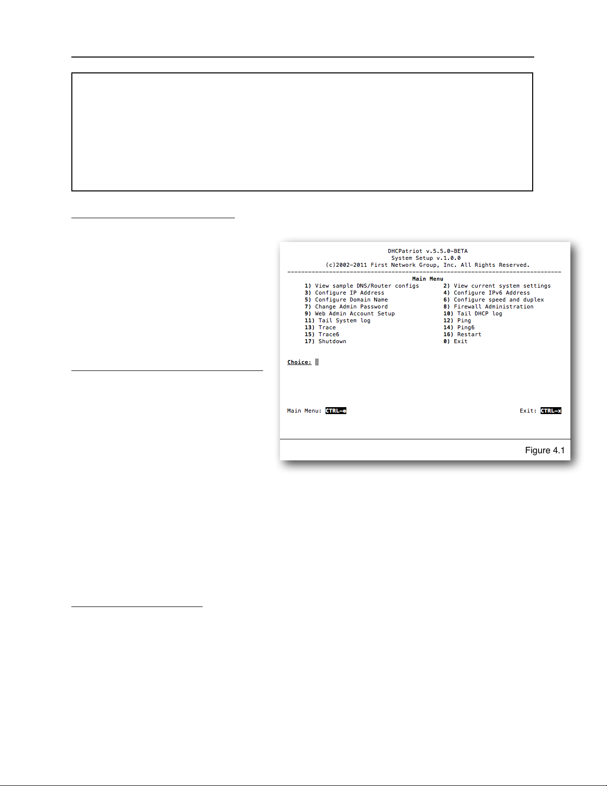
Configuring the Menu Interface
After connecting and logging on
using the administrator username, a
menu will be presented like the one
in figure 4.1. A series of steps are
necessary to complete this portion of
the configuration before moving on to
the Web Administration Interface
configuration stage.
Changing the ‘admin’ user password
The very first task to perform is to
change the default password for the
admin user. This password is widely
known (at least among DHCPatriot
system owners) and should not be
used after the IP address is set.
Once a suitable password is chosen, press 7 and then enter to begin the password
changing process. Press enter to move to the next screen. You will be prompted for
the old password. Type this and press enter. Type the new desired password and
press enter. Retype the new desired password and press enter to confirm. It should
report that the password was changed. Press enter. It should report that the password
change was successful. Press enter. You will be returned to the main menu. If
anything went wrong, try the procedure again.
IP Address Configuration
NOTE: Do not reboot until both the IP Address and domain name have been configured.
If the domain name is left at the default example.com, then the IP address will be
returned to default upon reboot.
To begin configuration of the IP address, press 3 and then enter. At this point, press 1
and then enter. That will begin the configuration process. The interface will ask for the
Chapter 4: Initial Configuration
20
DHCPatriot Version 6 Operations Manual This document © 2017 First Network Group Inc. All Rights Reserved
Figure 4.1
Table of contents
Popular Server manuals by other brands

innuos
innuos Sonos ZEN quick start guide

HP
HP Proliant DL580 Quickspecs

Sun Microsystems
Sun Microsystems Sun Fire X2270 Getting started guide

Fujitsu Siemens Computers
Fujitsu Siemens Computers PRIMERGY RX600 S3 Information guide

Overland Storage
Overland Storage SnapServer 110 Configuration and hardware options guide

HPE
HPE ProLiant DL360 Gen10 user guide

Fujitsu
Fujitsu PRIMERGY T850 System configurator and order-information guide

Vidicode
Vidicode Fax Server PRI manual

Seneca
Seneca XVAULT XNVR150 quick start guide

Ubiquiti
Ubiquiti UniFi Cloud Key Gen2 Plus quick start guide

AMX
AMX MAX-HT04 datasheet

Polycom
Polycom RSS 2000 Getting Started Guide & Release Notes


