FNW AC Series Guide

ACTUATOR
AC-SERIES
PNEUMATIC RACK & PINION ACTUATOR
INSTALLATION, OPERATION & MAINTENANCE INSTRUCTIONS
FNW.COM We reserve the right to modify or improve the designs or
specifications of our products at any time without notice.
1
1. INTRODUCTION
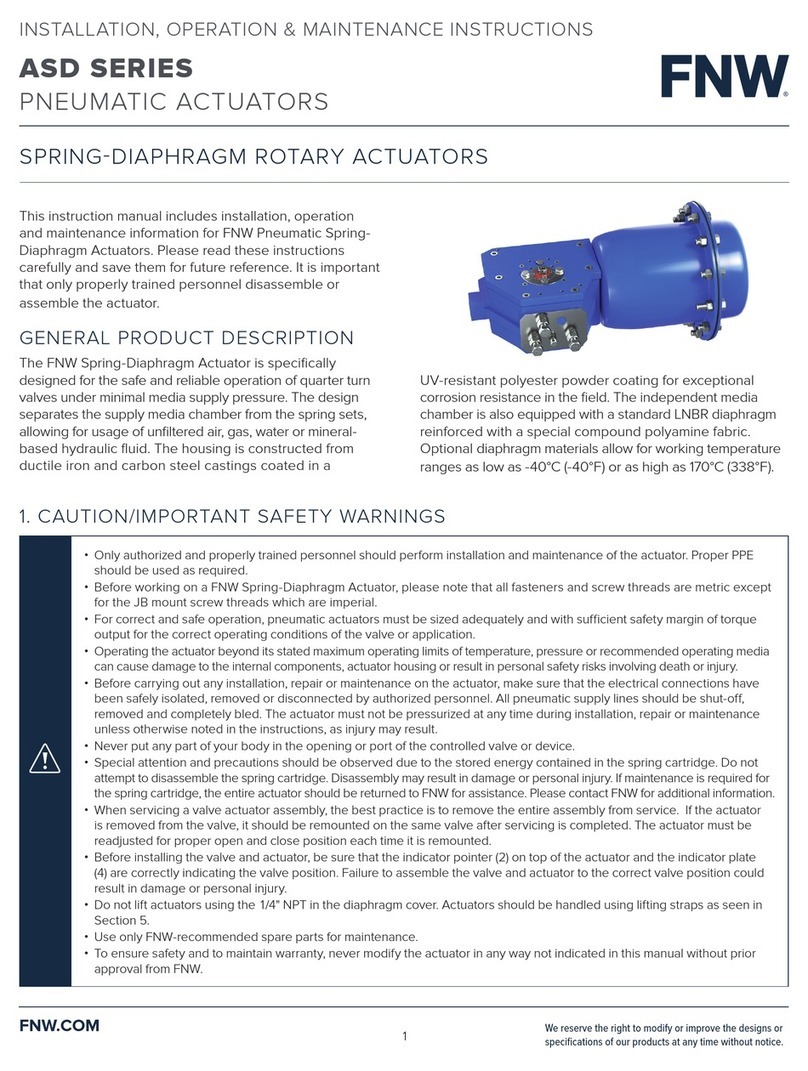
This instruction manual includes installation, operation, and maintenance information for FNW AC-Series Pneumatic Rack & Pinion
Actuators. Please read these instructions carefully and save them for future reference. It is important that only properly trained personnel
disassemble or assemble the actuator.
2. GENERAL PRODUCT DESCRIPTION
The FNW AC-Series Pneumatic Rack & Pinion Actuator is a double acting or spring return system designed for the actuation of ¼ turn
valves or ¼ turn applications. This actuator includes a top mount multifunction indicator and open-close stop adjustment as standard.
Additional design features ensure a long cycle life and low maintenance actuator.
3. CAUTION/IMPORTANT SAFETY WARNINGS
4. STORAGE
ATTENTION: If the actuators are not destined for immediate use, the following storage precautions should be taken:
• Ensure the actuator is completely dry and water free.
• Protect openings of air passages by fitting the original or replacement plastic corks if required.
• If possible, leave the actuators in their packaging during storage. Actuators should be protected to safeguard against humidity,
moisture, dust, dirt, sand, mud, salt spray, sea water, or other forms of corrosive and erosive environments.
• Only authorized and properly trained personnel should perform installation and maintenance of the actuator. Proper PPE
should be used as required.
• For correct and safe operation, pneumatic actuators must be sized adequately and with sufficient safety margin of torque
output for the correct operating conditions of the valve or application.
• Operating the actuator beyond its stated maximum operating limits of temperature, pressure or recommended operating
media, can cause damage to the internal components, actuator housing or result in personal safety risks involving death
or injury.
• Before carrying out any repair or maintenance on the actuator, make sure that the pressure supply lines and electrical
connections have been safely isolated, removed or disconnected by authorized personnel. The actuator must not be
pressurized at any time during installation as injury may result.
• Never put any part of your body in the opening or port of the controlled valve or device.
• Special attention and precautions should be observed due to the stored energy contained in the spring return pneumatic
actuators. Do not disassemble individual spring cartridges. Disassembly may result in personal injury.
• Before installing onto a valve, make sure that the rotation of the valve and the actuator are the same and that the position
indicator orientation is also correct.
• Use only FNW recommended spare parts for maintenance.
• To ensure safety and to maintain warranty, never modify the actuator in any way not indicated in this manual without prior
approval from FNW.

ACTUATOR
AC-SERIES
PNEUMATIC RACK & PINION ACTUATOR
INSTALLATION, OPERATION & MAINTENANCE INSTRUCTIONS
FNW.COM We reserve the right to modify or improve the designs or
specifications of our products at any time without notice.
2
5. OPERATING CONDITIONS
Operating media
• Dry or lubricated air, or non-corrosive gas. The maximum particle diameter must be less than m.
Air supply pressure
• The minimum supply pressure is psi.
• The maximum supply pressure is psi.
Operating temperature
• Standard (NBR O-ring): -°C to °C (-°F to °F)
• Low temp (LNBR O-ring): -°C to °C (-°F to °F)
• High temp* (FKM O-ring): -°C to °C (°F to °F)* Standard actuator construction
Travel adjustment
• Have adjustment range of ±/-° for the rotation at ° and °.
Application
• Suitable for both indoor and outdoor use.
Lubrication
• The actuator comes pre-lubricated; no additional lubrication is required.
6. PRINCIPAL OF OPERATION
Double acting actuator
A B A B
A B A B
0o90o
90o0o
A B A B A B A B
0o90o90o0o
A B A B A B A B
0o90o90o0o
A B A B
A B A B
0o90o
90o0o
A B A B
A B A B
0o90o
90o0o
A B A B A B A B
0o90o90o0o
A B A B A B A B
0o90o90o0o
A B A B
A B A B
0o90o
90o0o
Standard rotation (CCW):
Air to port “A” forces the pistons
outwards, causing the pinion to turn
counterclockwise while the air is being
exhausted from port “B”. Air to port “B”
forces the pistons inwards, causing the
pinion to turn clockwise while the air is
being exhausted from port “A”.
Reverse rotation (CW):
Air to port “A” forces the pistons
outwards, causing the pinion to
turn clockwise while the air is being
exhausted from port “B”. Air to port “B”
forces the pistons inwards, causing the
pinion to turn counterclockwise while the
air is being exhausted from port “A”.
Standard rotation:
Air to port “A” forces the pistons outwards,
causing the springs to compress. The
pinion turns counterclockwise while air is
being exhausted from port “B”. Loss of air
pressure on port “A”, combined with the
stored energy of the springs, forces the
pistons inwards. The pinion turns clockwise
while air is being exhausted from port “A”.
Reverse rotation:
Air to port “A” forces the pistons
outwards, causing the springs to
compress. The pinion turns clockwise
while air is being exhausted from port
“B”. Loss of air pressure on port “A”,
combined with the stored energy of the
springs, forces the pistons inwards. The
pinion turns counterclockwise while air is
being exhausted from port “A”.
Spring return actuator
Assembling the actuator and reversing the position of the pistons can easily reverse the standard rotation.

ACTUATOR
AC-SERIES
PNEUMATIC RACK & PINION ACTUATOR
INSTALLATION, OPERATION & MAINTENANCE INSTRUCTIONS
FNW.COM We reserve the right to modify or improve the designs or
specifications of our products at any time without notice.
3
7. VALVE ASSEMBLY
Pneumatic actuators are fitted with a double square "star" pattern drive shaft and a mounting bolt pattern
conforming to ISO Standards. This allows the actuator to be fitted to valves in increments of degrees, allowing
mounting alignment either inline or across the line of the pipe work, for the efficient use of space without the
position affecting the basic operation of the actuator.
• Fit the square of the valve directly into the square of the actuator.
• Ensure the actuator base is flat against the valve mounting flange and bolt together.
The following should be noted prior to assembly to the valve:
• Determine the desired operation of the assembly: Normally closed valve NC, or normally open valve NO.
• Check that the valve and actuator are in the same position (open or closed). Check the correct positioning (alignment)
of all the elements of the assembly, including the valve, connection piece, bracket and actuator.
• Torque the mounting screws in a diagonal pattern to equalize loading. Ensure all position indicators are correctly
adjusted and show the correct positions.
CAUTION:
When using a spring return actuator for a fail-safe operation, ensure that when air or electricity failure occurs the direction
of rotation is correct for your application.
8. ACTUATOR DISASSEMBLY AND MAINTENANCE
To disassemble the actuator (refer to the parts and materials list for identification):
• Safely disconnect all electric power and supply lines connected to the actuator and/or accessories.
• Disassemble all the accessories of the actuator (solenoid, limit switch box, etc.).
• Disassemble the screws and remove the actuator from the valve.
• Remove indicator screw () if fit, lift position indicator () off shaft (it may be necessary to pry gently with a screwdriver).
• Unscrew the end cap screws ().
• Remove stroke adjustment screw () together with nut () and O-rings ().
• Remove the end caps ().
• Rotate the pinion () counterclockwise so that the pistons () will exit the body ().
• Remove the snap ring () and the washers () and ().
• Remove the pinion (), cam () and inside washer () from the body of the actuator, with downward force to the top of pinion.
CAUTION:
When the actuator is a spring return unit, make sure that the actuator is in the failed position before disassembling.
Air pressure should not be used to remove the pistons from body.

ACTUATOR
AC-SERIES
PNEUMATIC RACK & PINION ACTUATOR
INSTALLATION, OPERATION & MAINTENANCE INSTRUCTIONS
FNW.COM We reserve the right to modify or improve the designs or
specifications of our products at any time without notice.
4
9. INSPECTION AND MAINTENANCE
MAINTENANCE IS RECOMMENDED EVERY , COMPLETED CYCLES.
Recommended Replacement Parts
• Clean the actuator as required.
• Inspect the components of the actuator for wear or damage and replace as necessary.
• Replace the following parts:
- On the pinion: Snap ring (), O-rings () and (), outside washer (), bearing (pinion top) () and bearing (pinion bottom) ()
- On the end caps: End cap O-ring ()
- On the pistons: O-ring (), piston guide (), bearing (piston) ()
- Springs: All fitted springs should be replaced during periodic maintenance.
- O-rings: All O-rings should be replaced during periodic maintenance.
• Outside washer ()
• End cap O-ring ()
• Snap ring ()
• Piston O-ring ()
• Pinion top O-ring ()
• Piston bearing ()
• Pinion bottom O-ring ()
• Piston guide ()
• Pinion top bearing ()
• Spring ()
• Pinion bottom bearing ()
• Adjustment screw O-rings ()
10. PARTS AND MATERIALS Item Description Qty Material
1 Indicator Screw 1 ABS Plastic
2 Indicator 1 ABS Plastic
3 Snap Ring 1 Stainless Steel 304
4 Thrust Washer 1 Stainless Steel 304
5 Outside Washer 1 POM (Acetal)
6 Body 1 Extruded Aluminum Alloy (6005-T5)
7 Piston Guide 2 POM (Acetal)
8 O-Ring (Pinion Top) 1 FKM
9 Bearing (Pinion Top) 1 POM (Acetal)
10 Inside Washer 1 POM (Acetal)
11 Cam 1 Steel Nickel Plated AISI 1045
12 Pinion 1 Steel Nickel Plated AISI 1045
13 Bearing (Pinion Bottom) 1 POM (Acetal)
14 O-Ring (Pinion Bottom) 1 FKM
15 Spring 1-12 Spring Steel
16 Bearing (Piston) 2 POM (Acetal)
17 O-Ring (Piston) 2 FKM
18 Piston 2 Die-Cast Aluminum A380
19 Plug 2 FKM
20 O-Ring (Adjusting Screw) 2 FKM
21 Nut (Adjusting Screw) 2 Stainless Steel 304
22 Adjusting Screw 2 Stainless Steel 304
23 O-Ring (End Cap) 2 FKM
24 End cap 2 Die-Cast Aluminum A380
25 Screw 8 Stainless Steel 304

ACTUATOR
AC-SERIES
PNEUMATIC RACK & PINION ACTUATOR
INSTALLATION, OPERATION & MAINTENANCE INSTRUCTIONS
FNW.COM We reserve the right to modify or improve the designs or
specifications of our products at any time without notice.
5
11. ACTUATOR ASSEMBLY
• Refit the pinion () into the body of the actuator (), ensuring the cam () is correctly fit during assembly. Verify correct cam position by
ensuring that the pinion will rotate in both the counterclockwise and clockwise directions when the stroke adjustment screws () are refitted.
• Fit washers () () and snap ring () to the top of pinion.
• Refit the pistons () into the body (). Both pistons should engage the gear of the pinion () at the same time.
• For standard rotation assembly, rotate the pinion () approximately to degrees in a clockwise direction until the pistons are correctly
retracted. Check that the pinion output end is square to the body and is correctly aligned.
• Mount the end cap () to the body and tighten the screws () distributing the force evenly until the end cap is securely home.
Caution should be taken not to “pinch” the O-rings during this assembly procedure. In spring return actuators, insert the spring
cartridges in the appropriate pattern shown below.
CAUTION:
Before beginning the assembly, verify that all the O-rings and gaskets are properly housed in their correct cavities and are
properly lubricated with a commercial lubricant which is compatible with the O-ring and gasket materials.
CAUTION:
Obtaining the correct gear tooth and piston alignment could require more than one attempt.
5 Springs 6 Springs
7 Springs 8 Springs
9 Springs 10 Springs
11 Springs 12 Springs
• Fit the stroke adjustment screw () with the
nut () and O-ring () into the body.
Endstop adjustment–clockwise (right adjusting screw)
• Loosen the nut () of the right-hand external stroke adjustment screw.
• Tighten or loosen the adjustment screw () until reaching the
required position.
• Tighten the nut () of the right-hand external stroke adjustment screw.
Endstop adjustment–counterclockwise (left adjusting screw)
• Loosen the nut () of the left-hand external stroke adjustment screw.
• Tighten or loosen the screw () until reaching the required position.
• Tighten the nut () of the left-hand external stroke adjustment screw.
Pressure test
• Pressure test the actuator with bar ( psi) clean, compressed air and
inspect for leaks using a soap and water solution sprayed on to all joints
and rotating shafts.

ACTUATOR
AC-SERIES
PNEUMATIC RACK & PINION ACTUATOR
INSTALLATION, OPERATION & MAINTENANCE INSTRUCTIONS
FNW.COM We reserve the right to modify or improve the designs or
specifications of our products at any time without notice.
6
12. LIMITED WARRANTY
Warranty
Subject to the limitations expressed herein, Seller warrants that products manufactured by Seller shall be free from defects in design,
material and workmanship under normal use for a period of one year from installation but in no case shall the warranty period extend
longer than eighteen months from the date of sale. This warranty is void for any damage caused by misuse, abuse, neglect, acts of God,
or improper installation. For the purpose of this section, “Normal Use” means in strict accordance with the installation, operation and
maintenance manual. The warranty for all other products is provided by the original equipment manufacturer.
Claim Process and Remedies
Seller shall repair or replace, at its option, any non-conforming or otherwise defective product, upon receipt of notice from Buyer
during the Manufacturer’s warranty period at no additional charge. SELLER HEREBY DISCLAIMS ALL OTHER EXPRESSED OR IMPLIED
WARRANTIES, INCLUDING, WITHOUT LIMITATION, ALL IMPLIED WARRANTIES OF MERCHANTABILITY AND FITNESS OR FITNESS FOR
A PARTICULAR PURPOSE.
In order to file a claim under the terms of this Warranty, a claimant must promptly notify FNW that a Product may be defective within
days of the suspected failure or defect via the telephone number, mail or website listed below and may be required to submit proof of
purchase and/or photographs.
• Telephone: ---
• Mailing Address: Lakefront Commons, Newport News, VA
• Website: fnw.com
All Products alleged to be defective must be sent to FNW for inspection and testing for determination of the cause of the alleged
defect or failure.
Limitation of Liability
UNDER NO CIRCUMSTANCES SHALL EITHER PARTY BE LIABLE TO THE OTHER FOR INCIDENTAL, PUNITIVE, SPECIAL OR
CONSEQUENTIAL DAMAGES OF ANY KIND. BUYER HEREBY ACKNOWLEDGES AND AGREES THAT UNDER NO CIRCUMSTANCES,
AND IN NO EVENT, SHALL SELLER’S LIABILITY, IF ANY, EXCEED THE NET SALES PRICE OF THE DEFECTIVE PRODUCT(S)
PURCHASED DURING THE PREVIOUS CONTRACT YEAR.
Labor Allowance
Seller makes NO ADDITIONAL ALLOWANCE FOR THE LABOR OR EXPENSE OF REPAIRING OR REPLACING DEFECTIVE PRODUCTS
OR WORKMANSHIP OR DAMAGE RESULTING FROM THE SAME.
Recommendations by Seller
Seller may assist Buyer in selection decisions by providing information regarding products that it manufactures and those manufactured
by others. However, Buyer acknowledges that Buyer ultimately chooses the product’s suitability for its particular use, as normally
signified by the signature of Buyer’s technical representative. Any recommendations made by Seller concerning the use, design,
application or operation of the products shall not be construed as representations or warranties, expressed or implied. Failure by Seller
to make recommendations or give advice to Buyer shall not impose any liability upon Seller.
Excused Performance
Seller will make a good faith effort to complete delivery of the products as indicated by Seller in writing, but Seller assumes no
responsibility or liability and will accept no back charge for loss or damage due to delay or inability to deliver, caused by acts of God,
war, labor difficulties, accidents, inability to obtain materials, delays of carriers, contractors or suppliers or any other causes of any
kind whatever beyond the control of Seller. Under no circumstances shall Seller be liable for any special, consequential, incidental, or
indirect damages, losses, or expense (whether or not based on negligence) arising directly or indirectly from delays or failure to give
notice of delay.
©2023 Ferguson Enterprises, LLC 0123 4868286
Table of contents
Other FNW Controllers manuals
