manuals.online logo
Brands
  1. Home
  2. •
  3. Brands
  4. •
  5. Honeywell
  6. •
  7. Controllers
  8. •
  9. Honeywell VCA Series User manual

Honeywell VCA Series User manual

The VC hydronic valve consists of a valve body and replaceable characterized
cartridge assembly.
Depending on the valve model selected, they can be used with a VC2114 or
VC8114 series actuator to provide on-off flow control, or with a VC6930 or
VC7930 series actuator to provide proportional flow control. Two way bodies
may be plumbed in either direction. Three-way bodies may be used in either
diverting or mixing applications.
Replacing the cartridge rebuilds the valve. The valve body should be able to
stay in the pipes indefinitely.
VC actuators, ordered separately, use cam-operated cartridge travel to resist
water hammer. Limit switches prevent motor overrun. These actuators are
available with conformal coated printed circuit boards for humidity resistance.
SPECIFICATIONS
The specifications following are nominal and conform to generally
accepted industry standards. Honeywell is not responsible for damages
resulting from misapplication or misuse of its products.
Operating Ambient:
32 to 150°F [0 to +65°C].
5-95% RH (non-condensing)
Fluid temperatures:
34 to 203°F [1 to 95°C]
Shipping and Storage Temperature:
-40 to 150°F [-40 to +65°C]
Atmosphere:
Non-corrosive, non-explosive.
Valve Materials:
Body of bronze Cartridge of Ryton(polyphenylene sulphide) and
Noryl(polyphenylene oxide)
O-ring seals of EPDM rubber
Stem of stainless steel
Pressure Rating:
Static - 300 psig [20 Bar] maximum.
Burst - 1500 psig [100 Bar]
Operating Differential and Close-off - 60 psi maximum [4 bar]
Stem Travel:
0.4 inches [10 mm]
Flow Characteristics: Linear or equal percentage, per Table 1.
Accessories and Replacement Parts:
40007029-002: Wrench for removing VC cartridge
VCZZ1100: 2-way linear flow characteristic cartridge
VCZZ1400: 2-way equal percentage cartridge
VCZZ1500: 2-way equal percentage cartridge, very low Cv
VCZZ1600: 2-way equal percentage cartridge, low Cv
VCZZ6100: 3-way linear flow characteristic cartridge
272866B: Flush caps for system cleaning, 10 per pack
Form No. 95C-10919
VCA,B,M, and N Series
Cartridge Valve for Use with VC Series Actuators
Figure 1 - Nominal dimensions in inches and millimetres
Table 1: VC Valve assembled dimensions
[4] Dimension
Pipe Fitting Sizes mm Inches mm Inches mm Inches
1/2" BSPP (int.) [2]
1/2" BSPT (int.)
3/4" BSPP (int.)
3/4" BSPT (int.)
3/4" BSPP (ext.)
22mm Compression [3] 112 4- /16 140 5-1/2
1" BSPP (int.) 94 3-11/16 136 5-11/32
1" BSPP (ext.) 95 3-11/1 114 4- /1 13 5-11/33
1" BSPT (int.) 94 3-11/16 136 5-11/32
28mm Compression [3] 116 4-9/16 14 5-13/16
3/8" FLARE [1] 98 3- /8 136 5-11/32
1/2" SWEAT 89 3-1/2 130 5-1/8
1/2" FLARE [1]
1/2" INVERTED FLARE [1]
1/2" NPT (int.)
3/4" NPT (int.) 130 5-1/8
3/4" SWEAT 132 5-3/16
1" NPT (int.)
1" SWEAT 5-11/32
1-1/4" SWEAT
1-1/4" NPT (int.)
[1] No adapter
[2] 15 mm compression
[3] Nuts and olives not included
[4] All models not available in all countries
ECD
113 4- /16
136 5-11/32
94 3-11/16 130 5-1/8
113 4- /16
98 3- /8 111 4-3/8
113 4- /16
NORTH AMERICA STANDARD MODELS
98
111 4-3/8
3- /8 5-11/32
5-5/8
136
136
110 4-5/16 118 4-5/8 142
94 3-11/16
ABB
AB
A
94 [3-3/4]94 [3-3/4]
DD
90 [3-9/16]90 [3-9/16]
C
94 [3-3/4]94 [3-3/4]
C
68 [2-3/4]68 [2-3/4]
E
E
2003.02.24
© Honeywell Limited.
2
Table 2: VC Series Valve Bodies
MODELS:
BODIES: VCA,B,M,N ..., per table: 1
ACTUATORS (ORDER SEPARATELY)
Figure 3 - Fluid flow of 3-way valves
AB <-> B
AB
B
A
AB
AB <-> A
Figure 2 - Fluid flow of 2-way valves
A B
Open
A B
Closed
2-way 000 00 400 500 600
Valve [5] Cartridge [4]
Number Pipe Fitting Sizes
VCZAF 1/2" BSPP
(
int.
)
[2] 2.6 0.6 .
VCZAB 1/2" BSPT
(
int.
)
2.9 0.6 .
VCZAJ 3/4" BSPP
(
int.
)
3.3 0.7 .3
VCZAK 3/4" BSPT
(
int.
)
0.7 .3
VCZAH 3/4" BSPP
(
ext.
)
VCZAG 22MM Compression [3] 4.6 3.7
VCZAP 1" BSPP
(
int
)
5.7 3.6 0.7 .3
VCZAQ 1" BSPP
(
ext.
)
5.3
VCZAT 1" BSPT
(
int.
)
5.7
VCZAN 28 MM Compression [3] 5.4
VCZAC 3/8" FLARE [1] 2.1
VCZAA 1/2" SWEAT 3.2 2.9 0. 1.3
VCZAD 1/2" FLARE [1] 3.1
VCZAE 1/2" INVERTED FLARE [1] 3.2
VCZBB 1/2" NPT
(
int.
)
3.4 2.9 0. 1.3
VCZAL 3/4" NPT
(
int.
)
4.
VCZAM 3/4" SWEAT 4.6
VCZAR 1" NPT
(
int.
)
6.6
VCZAS 1" SWEAT 6.2
VCZBE 1-1/4" SWEAT
VCZBD 1-1/4" NPT (int.)
Quick
O
p
en Linear
[6]
[1] No adapters
[2] Suitable for use as 15 mm compression fitting
[3] Includes compression nuts and olives
[4] " 200" series cartridge has the same Cv/kV rating as "1100" series.
Suitable for use in potable water appications.
1.50.8
4.2
3.9
FLOW CHARACTERISTIC
APPLICATION
Nominal kvs Rating [8]
NORTH AMERICA STANDARD MODELS
6.0
.0
Nominal Cv Rating
5.3
3.0
4.5
Equal Percentage
On-Off [ ]
Modulating
3-way
Valve [5] Cartridge
Number Pipe Fitting Sizes
VCZME 1/2" BSPP
(
int.
)
[2] 3.2
VCZMN 1/2" BSPT
(
int.
)
3.3
VCZMH 3/4" BSPP
(
int.
)
5.9
VCZMJ 3/4" BSPT
(
int.
)
5.3
VCZMG 3/4" BSPP
(
ext.
)
6.9 5.7
VCZMF 22 mm Compression [3] 7. 5.9
VCZMP 1" BSPP
(
int
)
6.4
VCZMQ 1" BSPP
(
ext.
)
6.8
VCZMT 1" BSPT
(
int.
)
6.9
VCZMM 28 mm Compression [3] 6.4
VCZMB 3/8" FLARE [1] 2.
VCZMA 1/2" SWEAT
VCZMC 1/2" FLARE [1]
VCZMD 1/2" INVERTED FLARE [1] 4.2
VCZNB 1/2" NPT
(
int.
)
3.
VCZMK 3/4" NPT
(
int.
)
6.6
VCZML 3/4" SWEAT 5.9
VCZMR 1" NPT
(
int.
)
8.6
VCZMS 1" SWEAT 6.6
VCZNE 1-1/4" SWEAT
VCZND 1-1/4" NPT (int.)
Quick
Open Linear
[6]
[5] Models are country specific. Some are not available in all countries
[6] Can be used for modulating with appropriate software
[ ] Use balancing valve for very low flow on-off applications
[8] Multiply the kv rating by 1.16 to obtain Cv rating
Example: 2-way, 3/4" BSPT (internal thread) valve number VCZAJ1400
has a kv rating of 3.9; 3-way 1/2" Sweat valve number
VCzMA6100 has a Cv rating of 3.8.
66006000 6 00 6400 6500
2. 0.6 1.1
1.50.8
4.2
Nominal
Cv
Rating
3.4
7.0
7.7
NORTH AMERICA STANDARD MODELS
FLOW CHARACTERISTIC
APPLICATION
Nominal
kvs
Rating [8]
3.8
8.6
Equal Percentage
On-Off [ ]
Modulatin
g
INSTALLATION
WHEN INSTALLING THIS PRODUCT:
1. Read these instructions carefully. Failure to follow them could
damage the product or cause a hazardous condition.
2. Check the ratings given in the instructions and on the product to
make sure the product is suitable for your application.
3. Installer must be a trained and experienced service technician.
4. Always conduct a thorough check-out when installation is completed.
5. While not necessary to remove the actuator from the body, it can be
removed for ease of installation. The actuator can be installed in any
of the four orientations to suit the most convenient wiring direction.
Actuator latching mechanism works only when the lengths of the
actuator and the valve body are parallel to each other.
6. An extra 1" (25 mm) head clearance above the actuator, is required
to remove the actuator.
PLUMBING
The valve may be plumbed in any angle, including vertical piping, but
preferably not with the actuator below horizontal level of the body.
Make sure there is enough room around the actuator for servicing or
replacement.
For use in diverting applications, the valve is installed with the flow
water entering through bottom port AB, and diverting through end ports
A or B. In mixing applications the valve is installed with inlet to A or B
and outlet through AB.
Mount the valve directly in the tube or pipe. Do not grip the actuator
while making and tightening up plumbing connections. Either hold
valve body in your hand or attach adjustable spanner (38 mm or 1-1/2")
across hexagonal or flat faces on the valve body (Figure 4).
3
If assembling valve train on a bench, take care not to deform body with
vice. Do not place the raised "H" logo between the jaws of the vice.
Excess jaw force can deform the body.
COMPRESSION MODELS
For compression fitted models, tighten the compression nuts enough to
make a watertight seal. TAKE CARE NOT TO OVER TIGHTEN.
Maximum torque limit is 33 ft-lb for the 22 mm compression fitting, and
48 ft-lb for the 28 compression fitting.
SWEAT MODELS
On sweat fitted valves, the cartridge is shipped loose to avoid being
damaged during the solder operation.
1. Remove valve actuator from body and solder the connecting pipes in
accordance with normal soldering practices.
2. After soldering and valve has cooled, remove cartidge assembly from
plastic bag, insert into the valve body and tighten down with enclosed
wrench until it bottoms out. DO NOT OVER TIGHTEN (maximum
torque is 40 in-lb). The top surface of the cartridge will be flush with
the top edge of the body casting. See Figure 5.
3. Replace valve actuator.
TO REPLACE CARTRIDGE (IF REQUIRED)
Two-way cartridges fit all two-way bodies. The Cv rating of a valve can
be changed by replacing the cartridge, allowing for unique
combinations. Three-way cartridges fit all three-way bodies.
1. Disconnect power supply before servicing to avoid electrical shock or
equipment damage.
2. Depending on the installtion, it may be necessary to disconnect leadwires
to valve actuator, or depress tab on Molex™connector and remove.
Where appropriate, label wires for rewiring.
3. Remove valve actuator by pressing up on the latch mechanism located
directly below the red manual open lever with thumb (See Figure 5).
Simultaneously press the actuator down towards the valve body with
moderate hand force and turn the actuator counter-clockwise by 1/8
turn (45°). Lift actuator off the valve body.
!IMPORTANT:
For trouble-free operation of the product, good installation
practice must include
initial system flushing, chemical
water treatment,
and the use of a
50 micron
(or finer)
system
side stream filter(s).
Remove all filters before
flushing.
Put the VC actuator manual lever in the 3-way actuator fully up
position or the fully open (down) position to allow initial system
flushing with the actuator mounted. This may be done without
electrical hook-up. Alternatively, reusable flush caps, part #
272866B, may be purchased separately for use in initial
flushing of dirty hydronic systems.
Do not use boiler additives, solder flux and wetted
materials which are
petroleum based
or contain
mineral oil,
hydrocarbons, or ethylene glycol acetate
. Compounds
which can be used, with minimum 50% water dilution, are
diethylene glycol, ethylene glycol, and propylene glycol
(antifreeze solutions).
CAUTION:
Disconnect power supply before connecting wiring to prevent
electrical shock and equipment damage.
On 24V systems, never jumper the valve coil terminals, even
temporarily. This may damage the thermostat.
!
Figure 4 - Plumbing of the VC Valve

4. To replace a cartridge, isolate flow to the valve using installed shut off
valves or other service equipment designed for this purpose. Remove old
cartridge with 40007029-002 wrench supplied with the replacement unit.
It
may be necessary to use pliers or other tools to remove the old cartridge
due to calcium or dirt buildup in the valve body.
5. Clean the valve surfaces marked *and ** in Figure 6 to ensure the new
cartridge O-rings seal at these points. Use care to avoid damage to these
surfaces ( ** for 3-way valves only).
6. Remove the pre-lubricated cartridge assembly from its plastic bag.
Thread it by hand into the valve body and tighten it down with the
enclosed wrench until it bottoms out. DO NOT OVER TIGHTEN:
maximum torque is 40 in-lb. [4.5 Nm]. The top surface of the cartridge
should be flush with the top edge of the body casting.
7. Replace valve actuator by following the procedure in the "To Install Actuator"
below.
8. Reconnect leadwires or Molex™connector if necessary.
9. Refill hydronic system or restore system flow by opening isolating valves.
10. Restore power, and checkout operation of cartridge in valve, making sure
of no internal seat leakage or external body leakage.
Restore system pressure slowly to the valve to allow any trapped air to
escape. Check for leaks. Re-install the actuator.
TO INSTALL ACTUATOR
NOTE: Installation of a new actuator does not require draining the system,
provided the valve body and valve cartridge assembly remain in the
pipeline. Wiring may be done either before or after the actuator is installed.
Refer to the VC Actuator Installation and Instruction sheet for detailed
wiring and check-out instructions.
1. The actuator head is automatically latched to the valve. Align the
coupling hole in the bottom of the actuator with the valve stem.
Press the actuator down towards the body with moderate hand
force and turn the actuator counter-clockwise by 1/8 turn (45
degrees) to line up the actuator with the piping. The lock will click
when engaged (See Figure 7).
NOTE: The actuator can also be installed at right angles to the valve
body but in this position the lock mechanism will not engage.
2. Connect leadwires.
3. Restore power and check operations.
Figure 7 - Lock Mechanism to detach Actuator
Figure 5 - Installing Cartridge Figure 6
SERVICE
This valve should be serviced by a trained, experienced service
technician.
1. If the valve is leaking, drain system OR isolate valve from the
system. Do not remove valve body from plumbing.
2. Check to see if the cartridge needs to be replaced.
3. If the motor or other internal parts of the actuator is damaged,
replace the entire actuator assembly.
NOTE: Honeywell VC series hydronic valves are designed and tested
for silent operation in properly designed and installed systems.
However, water noises may occur as a result of excessive water
velocity. Piping noises may also occur in high temperature (over
212oF [100oC]) systems with insufficient water pressure.
Automation and Control Solutions
Environmental Control Products
1985 douglas Drive North
Golden Valley, MN 55422-3992
U.S.A.
In Canada:
Honeywell Limited-Limitee
35 Dynamic Drive
Toronto, ON M1V 4Z9
Canada
Printed in Canada

This manual suits for next models

3

Other Honeywell Controllers manuals

Honeywell VC2 Series, VC4 Series, VC60 Series,... User manual

Honeywell

Honeywell VC2 Series, VC4 Series, VC60 Series,... User manual

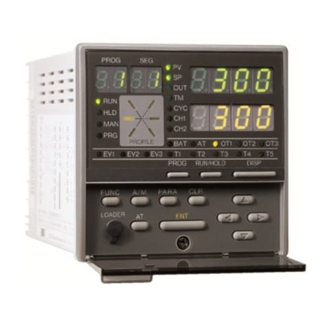
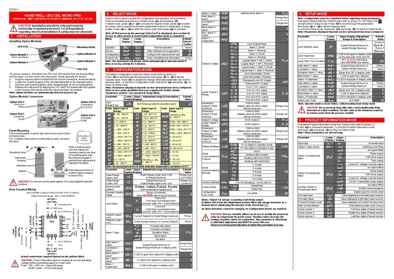
Honeywell UDC1200 MICRO-PRO User guide

Honeywell

Honeywell UDC1200 MICRO-PRO User guide

Honeywell WV8840A User manual

Honeywell

Honeywell WV8840A User manual

Honeywell HR92UK User manual

Honeywell

Honeywell HR92UK User manual

Honeywell SDW 30 User manual

Honeywell

Honeywell SDW 30 User manual

Honeywell T7560B User manual

Honeywell

Honeywell T7560B User manual

Honeywell M847D User manual

Honeywell

Honeywell M847D User manual

Honeywell ControlEdge 900 platform Technical manual

Honeywell

Honeywell ControlEdge 900 platform Technical manual

Honeywell TheraPro HR90 User manual

Honeywell

Honeywell TheraPro HR90 User manual

Honeywell 10260S Series User manual

Honeywell

Honeywell 10260S Series User manual

Honeywell S4965V3250 Operating and installation instructions

Honeywell

Honeywell S4965V3250 Operating and installation instructions

Honeywell Air Alert 96d User manual

Honeywell

Honeywell Air Alert 96d User manual

Honeywell UDC2800 User manual

Honeywell

Honeywell UDC2800 User manual

Honeywell Vista Automation Module User manual

Honeywell

Honeywell Vista Automation Module User manual

Honeywell CENTRA LINE MERLIN NX Series Installation and operation manual

Honeywell

Honeywell CENTRA LINE MERLIN NX Series Installation and operation manual

Honeywell W7752D2007 User manual

Honeywell

Honeywell W7752D2007 User manual

Honeywell INCOMM L510 User manual

Honeywell

Honeywell INCOMM L510 User manual

Honeywell HC900 User guide

Honeywell

Honeywell HC900 User guide

Honeywell ML9185 User manual

Honeywell

Honeywell ML9185 User manual

Honeywell Aquastat L7224U User manual

Honeywell

Honeywell Aquastat L7224U User manual

Honeywell Lyric LCP300-LC Product information sheet

Honeywell

Honeywell Lyric LCP300-LC Product information sheet

Honeywell CLMEVA00IB24NM User manual

Honeywell

Honeywell CLMEVA00IB24NM User manual

Honeywell UDC3500 User manual

Honeywell

Honeywell UDC3500 User manual

Honeywell WEB/CP-202-XPR User manual

Honeywell

Honeywell WEB/CP-202-XPR User manual

Popular Controllers manuals by other brands

Woodward 505 Installation and operation manual

Woodward

Woodward 505 Installation and operation manual

EverFocus EFC304 user manual

EverFocus

EverFocus EFC304 user manual

Texas Instruments bq24013 user guide

Texas Instruments

Texas Instruments bq24013 user guide

TRIATEK HMS-1655L installation manual

TRIATEK

TRIATEK HMS-1655L installation manual

Rockwell Automation Allen-Bradley SMC-3 Installations

Rockwell Automation

Rockwell Automation Allen-Bradley SMC-3 Installations

ICP GDT8514RZ Installation

ICP

ICP GDT8514RZ Installation

NAiS AFP3434 Guide book

NAiS

NAiS AFP3434 Guide book

BEKA BA454D manual

BEKA

BEKA BA454D manual

Fluidwell F Series manual

Fluidwell

Fluidwell F Series manual

T-Industry STM32F407 user guide

T-Industry

T-Industry STM32F407 user guide

Light O Rama CMB24D DMX user manual

Light O Rama

Light O Rama CMB24D DMX user manual

SMAR LC700 user guide

SMAR

SMAR LC700 user guide

Siko MSA501 user manual

Siko

Siko MSA501 user manual

Sens SuperTorque 8Z Installation & operation manual

Sens

Sens SuperTorque 8Z Installation & operation manual

Chauvet Obey 70 user manual

Chauvet

Chauvet Obey 70 user manual

Elan OLE XL Specifications

Elan

Elan OLE XL Specifications

Montalvo Z4-UD Technical manual

Montalvo

Montalvo Z4-UD Technical manual

Danfoss MCO 351 operating instructions

Danfoss

Danfoss MCO 351 operating instructions

manuals.online logo
manuals.online logoBrands
  • About & Mission
  • Contact us
  • Privacy Policy
  • Terms and Conditions

Copyright 2025 Manuals.Online. All Rights Reserved.