foc.us FC-1202 User manual

cul
Professional Mixing Consoles
Operating Instructions
FC-802 8 Channel
FC-1202 12 Channel
FC-1602 16 Channel
FC-24A2 24 Channel

Thank you for choosing a FOCUS mixing console. We are sure that it will provide you with
many years of reliable service.
FOCUS mixers are available with 8,12,16 and24 channels. Each channel offers Mic
and Line Inputs, an lrsert poin! Gain control with peak LED, 3 bands of Equalisation, 3
Auxiliary sends, Pan control, Cue switch and a master slider.
The output section consists ofleft and Right master sliders, balanced and unbalanced
outputs, 2 retums, headphone socket and phantom power switches.
The use ofthese controls will be discussed throughout this manual.
A correctly set up mixer is the key to a good, clear sound. This section is designed to
help the you with an initial set up of all the levels and controls.
Connect the mixer to mains power and switch on. A red LED on the far right hand side
will indicate power.
You will need two microphone leads (3 pin XLR) or two guitar leads (l/4" jacks) to
connect the mixer to your amplifier. These leads run from the GRP/OUTPUT sockets just left
of the power switch to the Left and Right (or A & B) inputs of your amplifier.
After checking that the master faders are hrned down, switch on your power anplifier.
The next step is to plug all your inputs into the mixer. Microphones should be plugged
into the 3 pin )(LR socket, while line inputs such as cD players, tape decks, keyboards etc,
should be plugged into the l/4" line socket.
A very important section of any mixer is the gain contol, which is the first knob on
each channel. The idea is to set this conhol as hi& as possible without the Peak LED coming
on. Adjust each charmel individually while the mics or inputs are being used in their normal
way. The cenfre position is a good starting point.
The next three controls are for Equalization. tIF stands for high frequency, MID for
Middle frequency, and LOW for low frequency. These confiols allow you to tailor the sound

of each input. The starting point for these confrols is in the centre position.
of Equalization is to improve the sound, so feel free to experiment.
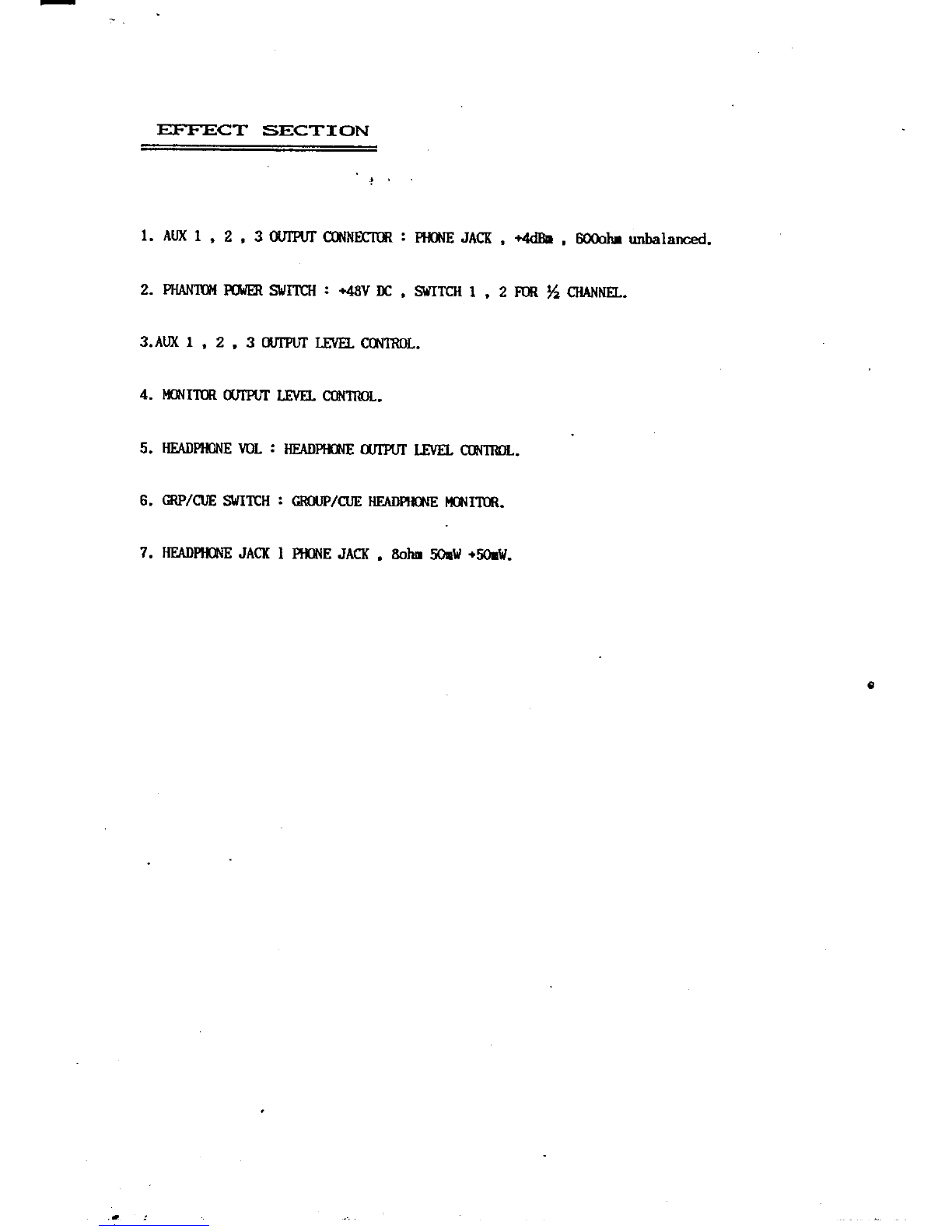
The AIIX l, A{IX 2 and AtX 3 confiols are only needed when using effects (reverb,
digital delay etc), or when using a foldback (monitor) system. Please see the separate section
on Auxiliaries.
The main purpose
The PAN contol is similar to the balance control on a home
each input to either the left or right output, or anywhere in between.
the cenhe.
stereo. It simply sends
The normal setting is in
The CUE button is used in conjunction with the headphone socket. When the CUE
button is on, it allows you to monitor individual inputs through the headphones. When using
cuE, neither the channel or master sliders need to be turned up. To use cUE, you also need
to press ttre GRP/CUE button near the headphone socket.
h GRP mode, you can monitor the entire mix, which is basically the sigral that is being fed to
your amplifiers. The VOL lnob contols the volurne of the headphones.
The slider at the bottom ofeach channel confiols how much ofeach input is sent to the
output section. It is simply a volume control for each channel.
To get any sound from your mixer, both the channel slider and the master slider need to be
tumed up.
The above information is all that you need to known to set up and operate a basic
system. Practice and hands-on experience will make you an expert.
The next stage of this booklet deals with the more advanced features of the mixer.
Auxiliaries are known as sends because they are used to send a signal out ofthe mixer.
You will notice that each channel has 3 auxiliaries, and that there are 3 master Auxiliaries on
the far right hand side of the mixer. There are also three l/4" Atxiliary output sockets.
Auxiliaries are normally used for foldback and/or effects, but can also be used to recording or
to feed a hearing loop arnplifier.
Foldback:
This term refers to a monitoring system usually comprising of another amplifier and
onstage speakers. Foldback is used so that performers can hear themselves while on stage.
A foldback (monitod system would norrnally be connected to AIIX l, because this is
pre-fader, which means that the channel slider has no effect on the aux output.

To connect a foldback system, run a lead from the AIIX 1 output to the line input of
you power amplifier. As a starting point set the Aux I master in the centre position and slowly
raise the Aux I control on the channel that you are using. Adjust the Aux I for each channel
that is required for foldback so that you have a suitable mix ofall the channels in the foldback
speakers.
Effects:
AI-IX 2 and 3 are post fader which means that the position of the channel slider affects
the amount of level being sent to these auxiliaries. Aux 2 and 3 would normally be used for
effects.
When using effects, the Auxiliary ou@ut sends the signal out of the mixer, but the effect
has to be returned and combined with the original sigrral. To connect an effect, run a lead from
the Aux 2 or 3 output to the input of yow effects units. The effects unit will have one or two
outputs (2 for stereo), which need to be connected to the returns of the mixer. T\e Focus
mixers have two retum inputs which are positioned just below the master outputs. The
Volume and Pan contols for the returns are below that master LEDs.
The return volume tells the mixer how much of the sigral with effects is being rehrmed.
The retum Pan contol allows you to decide if the effect is going to be mixed with both
the left and right outputs or anywhere in between.
When returning a stereo effect, run the left effect output into Return I and Pan firlly left,
and return the right effect output into Return 2 and Pan fuflV right.
This will maintain the stereo image that is created from the effects unit.
Another method of retuming effects is to use the line input of a spare channel. This
allows you to EQ the retum and control the retum level from a slider.
If you use this method, please make sure that the Aux that you are retuming is
completely tumed down on tlte channel, otherwise you will experience some loud squeals.
Foczs mixers have an monitor output which sends the entire mix post faders to the Left
and Right 1/4" monitor outputs.
The MON contol which is situated just above the headphone volume knob controls the
amormt of level going out the monitor outputs.

The monitor outputs would normally be used to feed another audio source such as a a
house PA system, or to nrn to a tape recorder. Please note that the monitor level is varied by
both the charurel and master sliders.
For foldback, it is best to use the ALIX I send, urs this provides a control on each
channel, and allows you to set the levels pre-fader. Please see the Auxiliaries section.
Phantom Power is needed when using electret/condenser microphones. These type of
mics (usually gooseneck or tie mics) require a voltage from the mixer to work.
With the Focus mixers, you can have phantom power on either the first half or second
half of the mixer, or on every channel.
There are two phantom power switches just below the AIIX outs. The green LED
indicates when phantom power is on.
Please note that phantom power cannot be used with unbalanced microphone
To maintain the effect of stereo, you will need to use two channels of the mixer, one
channel for left and one for right. Set the channels up identically except for the Pan controls.
One pan should be set completely left and the other completely right.
If you are not using effects, you can use the retums as inputs. This will not grve you atry
equalisation, but it will allows you to confol the volume and pan controls.
Every channel of the Focus mixers has a l/4" insert socket. An insert point allows you
to send your sigral out ofthe mixer and return it through the same socket. It can also be used
as a direct channel output.
The insert point is normally used to place processors (Compressors, Equalizers, Noise
Gates etc) across a signal channel. It therefore requires a 3 conductor (stereo) jack.
Please contact your nearest Focus dealer ifyou require any more infonnation

ra
!l
5.
5.
:i
i<!
ti..
rlI
I
I
V
I
:l
.J
o
o
o
o
o
o
o
o
o
o
o
o
o
o
o
o
o
o
o
!!
I
l,
T
I
ir
i l:
:*
il
l'I
"t
JJ
<l
_t
\l'
(
)P!
5i
:1 E'

INPUT MODUI-E FEATUFTES
!
1. MIC INItIT @NNECIW.S : XIR , -60d8 - -20dBu , 2l(ohr , electronical ly balanced.
2. LINE INPW CII'INEC"IDRS : E0'lE J CN , -20dh - +lOdBu , 101(ohr , electronical ly balan<x-d.
3. CI{ANNEL INSERT CU{NECTffi : -10dBu , SEND & RETURN , TIP SRID , RING RETT RN ,
SEND can be used for DIRECT CUTPUT.
4. PFAI( : A peak lrn will light should signal in the rcdule exeed jl?dBs.
This is at least 3dB BELtllr/ cl ippirg.
5. GAIN : {odB - -20d8 INPUT LEVE C.NIR'L. (MIc)
-20d8 - +lodB INFUT LEVE C(}'{I8OL. (LINE)
6, EqJALIZn : HF : 15dB of cut or boost at 10l0lz.
. llF : 1SB of cut or boost , at lxllz.
LF : l5dB of cut or bost at 10Ollz.
7. A{IXILIARIES
AUXI : internal ly link fnE FADR.
AlDo : interrlal ly link F(]SI FADB.
AUX3 : internal ly link F6'f FADR.
8. PAN FOT :. PANPOT L - GRCT,P LEFT
PANKITR-GNflJPRIC,T{T
9. C-tE Sltll€ll : In this rod€, tlE PRE-FN)ER SIQ,IAL is rorted to tlE CU'ITROL mil H(I'IITW and
lreadphone drtput uithout affect irg tlte rain console cutputs.
IO. 6OI,IH CIIANNEL FADM.

EFFEC:T SECTI ON
l. AtlX 1, 2, 3 OIfPUf qXNtrm : E0,lE JACK, +4dh, 60oohr unbalarred
2. PIIANIU'I F0ttrER SlllTf,l{ : +,tt}V If, , SaITCH I , 2 Fm % 611ANNH..
3.AIX I, 2, 3 q'TPUT LEVEL CO'ITROL.
4. Ifi{nm utfPUT LEvH- q IT{OL.
5. HEADHilI'IE VOL : HE{DNT$IE qITPI'I LEYN. fiNIRfl-.
6, cRP/Ct E St'rIIf,H : cRilP/CuE HEADPIU,|E ircNlfin.
7. HEADPiIIIE JACI( I PtlilE JACK . 8oh! 5htt +5011{.

GFTOT.IP MASTEFT < OU:TPUT SECTION >
r..
1. GR0JP OIITUT UR C€hlNEC,IIn : XlR, OdBu , 600oh , gr,crlnd drFnsated electronical ly balarcd.
2. GRotlP UII?(Ir UR CC[rlNECmn : plfiilE JACK , O4dBu , 6@cftr unbalanced.
3, RETURI,I INPUT CCIINECI{RS : Ptn'lE JACK , -fOdB , lOf,oha unbalanced.
4. 12 segnent Lm UEIER. : GnfUP LEFT/RIGIIT LED aeter,
, 5. RSNJRN INR'T VOL : RETUNN INPTIT LSYEL CThIITOL.
6. RE,IUR PAN PM : PANPOT L - GROIIP LEFT.
PNPOTR-GRCUPRIG}IT.
7. 6O['IU GRCIJP I{ASTER (I.EFT/RIG}JT) FADR.
This manual suits for next models
3
Table of contents