Focal Power Symmetric User manual

FOCAL
POWER
SYMMETRIC
AMPLIFIERS
User
manual
·i''''.!I~.i
We thank
you
for choosing
Focal
amplifiers for your
Car
Audio
system
and for sharing our philosophy:
"the Spirit of Sound".
This
product offers the latest advances
in
Focal amplifiers.
In
order to obtain
the best results, we highly recommend you have your new amplifier installed
by
your local Focal
distributor.
To
maximise the
use
all your amplifier functionalities and
to
fully enjoy
its
performance
levels, we recommend
you
read the entire instructions
in
this
booklet. We recommend you keep
this
manual for future reference. Any problem due to misapplication can lead
to
aguarantee
invalidation.
The
Focal
Guarantee
only
applies
if
the
next to last
page
is
returned
to
us
within
10
Days
of
purchase. "
AWARNING
!
This
symbol denotes important instructions.
Non
respect
of
these instructions
maylead
to serious
injuries and even fatal injuries.
ACAUTION
!
This
symbol denotes important instructions.
Non
respect
of
these instructions may lead to injury
or
material damage.
Content of the packaging:
- 1 amplifier
- 1 user manual
- 4 fixing screws
-
Fuses
- 1 remote control cable
(FPS
1500,
FPS
2300RX and
FPS
4160)
- 1 remote control
(FPS
1500,
FPS
2300RX and
FPS
4160)
• 1 hex
key
FO
the
spirit
of
sound
CE
Focal-JMlab®
-
BP
374
-
108,
rue de
l'Avenir
-
42353
La
Talaudiere
cedex -France -
www.focal-fr.com
Tel. (+.33)
04
77
43
57
00
-
Fox
(+33)
04
77
43
57
04
Due to constont technologicol odvances, Focal reserves
its
right to modify specifications without notice. Images may not conform exactly to specific product
..

FOCAL
POWER
SYMMETRIC
AMPLIFIERS
User
manual
&WARNING
II
-
Do
not
turn
on
any
function
which
may
distract
you
while
driving
the
vehicle. Functions requiring
sustained attention must only
be
used
when
the
vehicle
is
at acomplete standstill. Make
sure
to always stop
your vehicle
in
asafe place before operating these functions. There
is
a
risk
of causing
an
accident.
-Keep
the
volume
at
a
low
level
to
be
able
to
hear
exterior
noises
while
driving
the
vehicle.There
is
a
risk
of causing an accident.
-
Do
not
open
the
amplifier
or
undertake
any
modification
of
the
product.
There
is
a
risk
of accident,
fire
or
electric shock.
-Only
use this
amplifier
with
12V
mobile
applications.
Any
other
use
other than
the
use
for which this
product
has
been designed may lead to fire, electric shock
or
injury.
-Use
fuses
of
the
correct
amperage.
There
is
a
risk
of
fire
or
electrocution.
-Do
not
obstruct
radiators
and/or
vents. Internal overheating may occur and
cause
afire.
-Ensure
all
connections
are
properly
made.
Check the section of cable and the type
of
cable if it does not
correspond with the
use.
There
is
a
risk
of fire, injury
and/or
damage to the product.
-Do
not
use nuts
or
fasteners
part
of
the
steering
or
braking
systems
for
ground
connection.
The
fasteners and nuts
used
for the brake and steering
systems
(or any other security
system)
as
well
as
various
tanks must never
be
used
for grounding.
Use
of these parts
as
ground may deactivate the vehicle's control
system
and cause afire
or
other technical problem.
-Keep
all
small
objects
which
could
be
swallowed,
such as
the
fasteners
and
screws,
out
of
the
reach
of
children.
Swallowing
such
objects
may
cause serious injuries.
In
the event of swallowing any
of
these
objects, immediately
seek
medical advice.
-Before
starting
the
installation,
disconnect
the
negative
terminal
of
the
battery
to avoid any
risk
of
injury, fire
or
damage to the equipment.
Pic.
1

FOCAL
POWER
SYMMETRIC
AMPLIFIERS
User
manual
&CAUTION
Listening for prolonged periods at ahigh sound level, over
11
OdB,
can lead to permanent
deterioration
of
your hearing. Listening at alevel over 130dB, even for short periods of time, can
cause incurable
damage
and injury to your hearing.
Stop operation
in
the event of aproblem. Failure to heed this precaution may result in injuries
or
damage
to the product.
If
aproblem persists, return the product to your Focal distributor
for
repair.
Use the specified accessories and be sure to install them correctly.
Only
use
the accessories specified in
the user's manual and those which are supplied with the package. The
use
of
other components could cause
internal
damage
to the product, and their installation may not
be
correct. The parts being used risk becoming
loose and causing damages
or
technical faults with the product.
Do not assemble in very humid or dusty places. Avoid assembling the product
in
places with high levels
of
humidity
or
an excessive presence
of
dust. Humidity
or
dust getting inside the product may cause atechnical
fault.
Installation of the amplifier
The installation
of
this product requires technical knowledge and experience.
In
case you are uncertain
of
your
ability to correctly install the amplifier,
we
strongly recommend you contact your Focal retailer
who
will install it
for
you,
so
that you will be able to take full advantage
of
all the different possibilities
of
the amplifier.
Wiring of the amplifier
Only
use
the wires recommended in this manual. The loudspeakerwire must ONLY
be
used
for
connecting the
amplifier to the loudspeakers. The section
of
power cables must correspond to the one detailed in the
table (page
7)
and
correspond to the power
of
the amplifier and the length
of
the cable. Use
double
or
triple
shielded
RCA
cables to avoid any interference
of
the low level signal.
Duration of operation of the amplifier
Avoid using the amplifier
for
more than
10
minutes before starting the vehicle.
This
may cause the battery to
go
flat.
Progressive controlled cooling
system
The cooling system only works when the amplifier temperature exceeds
50°C.
The rotation speed
of
the cooling
system
depends on the amplifier temperature.
You
mustn't cover the amplifier
as
it could create overheating.

FOCAL
POWER
SYMMETRIC
AMPLIFIERS
User
manual
Required material for installation:
D
• 2 suitable cross-section sheaths
(1
sheath
for
the power supply cable), sheath for the speaker cables,
REMOTE,
RCA
signal and
REMOTE
CONTROL cables}
•Multimeter (voltage/amperage)
•Soldering iron +tin
•Crimping tool
•Stripping pliers
•Wire cutter
•Spanner
for
battery terminal
•Hand drill and assorted drills
•Heat sheaths
of
suitable diameter for the different cables
•Power cable
of
suitable length and section
•Remote turn on cable
(REM
input
of
amplifier)
of
suitable length and section
•Ground cable
of
suitable length and section
•Assorted connectors
•
Fuse
holder and suitable fuse
•Joint tag
for
the battery's positive (+) terminal
•Joint tag
for
the vehicle's chassis
(-)
•Screw with minimum 6mm screw head and
its
nut for ground connection to the chassis
of
the vehicle

FOCAL
POWER
SYMMETRIC
AMPLIFIERS
User
manual
Installation:
II
The
below section deals with
issues
regarding the vehicle which are necessary to take into account
for
the
installation
of
the amplifier. You'll
save
time
by
planning the
system
layout and wiring
in
advance. Please
ensure during this preparatory time that the whole settings remain accessible once the installation
is
complete.
Before starting the installation, please follow these rules carefully:
1 - After reading the whole manual,
be
sure that you have understood all the instructions before installing
the amplifier.
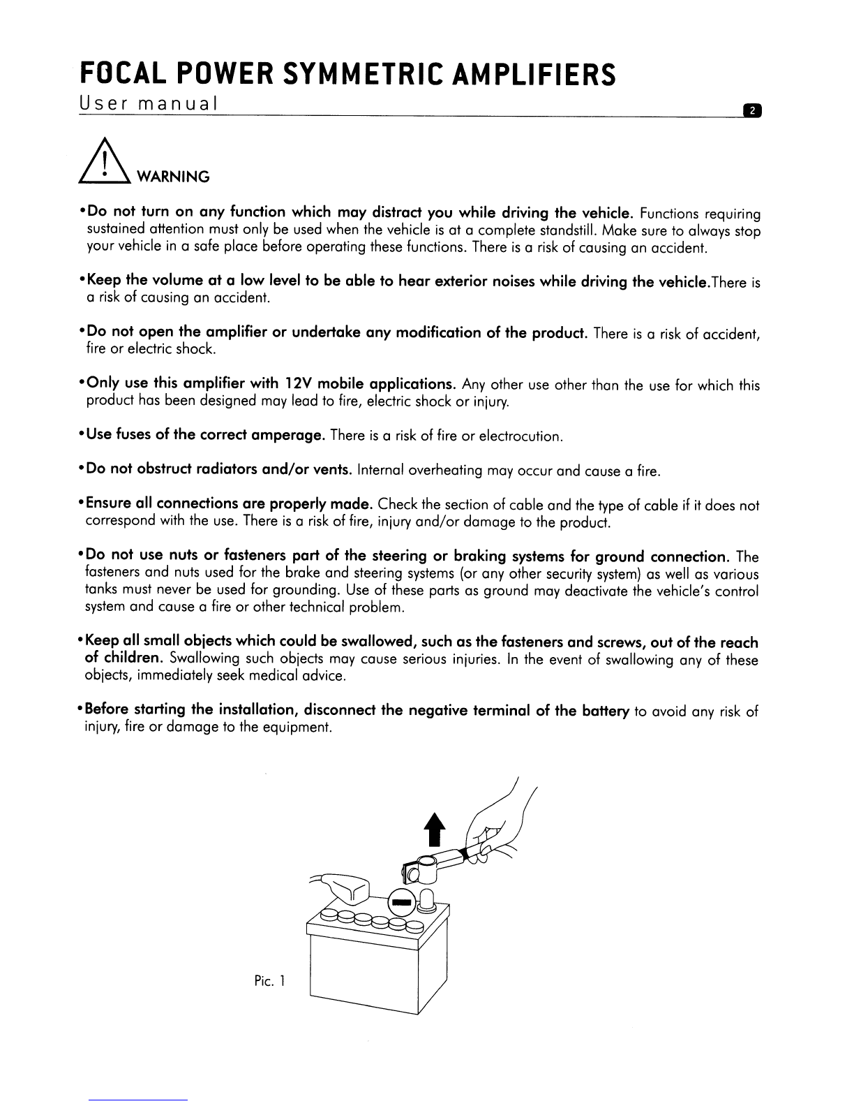
2 - Disconnect the battery's negative wire before starting the installation. (pic.
1).
3 -
To
facilitate the assembly,
we
strongly recommend you unwind all the wires before installing the
amplifier.
4 -
Put
aside all the
RCA
cables, speakers,
REM
and REMOTE CONTROL {REMOTE
CONTROL
only with
FPS
1500,
FPS
2300RX and
FPS
4160},
far from the power cables
in
order to avoid any interference
of
the signal.
5 -
Use
quality connectors to ensure areliable installation and to minimise any losses
of
signal
or
power.
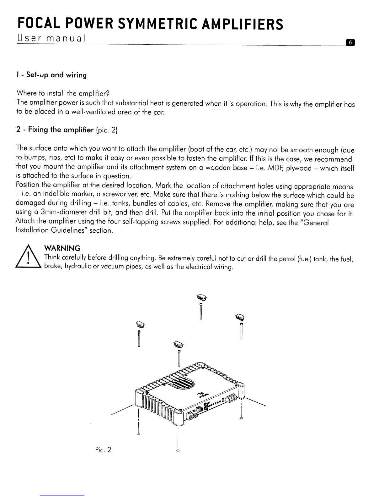
6 - Think carefully before drilling anything.
Be
extremely careful not to cut
or
drill the petrol (fuel) tank, the
fuel, brake, hydraulic
or
vacuum pipes,
as
well
as
the electrical wiring.
7 - Never route awire under the vehicle.
It
is
absolutely imperative to install them inside the vehicle
for
better protection. While routing the wires, verify that they
do
not impair the driving
of
the vehicle.
Cables obstructing
or
routing through areas such
as
the steering wheel, pedals (brake, accelerator and
clutch, etc.) may
be
extremely dangerous.
8 - Avoid routing wires above
or
through sharp rims. Any wire routed through metal must
be
protected
with agrommet. Route the wires well away from mobile parts (seat rails,...)and from sharp
or
pointed
cutting edges. This will avoid catching
or
damaging
the wires.
9 - Always protect the battery and electrical circuit from potential damages with the help
of
fuses. Install a
fuse
holder
and suitable fuses on the 12V positive (+) power cable at
less
than
40cm
from the battery
terminal. Ideally, this abovementioned distance should
be
the shortest
as
pOSSible
(pic. 4).
10
-Prepare the chassis ground
by
scraping any trace
of
paint on the metal surface
in
order to ensure
correct grounding.
The
grounding connections should also
be
as
short
as
pOSSible
and
ALWAYS
connected to the metal welded to the body
orthe
chassis of the vehicle (pic. 4).
The
generally chosen
ground point
is
the one that ensures the link between the negative terminal of the battery and the
chassis
of
the vehicle.
11
-
NEVER
install this product
in
the engine compartment
of
the vehicle.
This
will cancel the guarantee.

FOCAL
POWER
SYMMETRIC
AMPLIFIERS
User
manual
I-Set-up and wiring
II
Where to install the amplifier?
The
amplifier power
is
such that substantial heat
is
generated when it
is
operation.
This
is
why the amplifier has
to
be
placed in awell-ventilated area
of
the
car.
2 -
Fixing
the amplifier (pic. 2)
The
surface onto which you want to attach the amplifier (boot
of
the car, etc.) may not be smooth enough (due
to bumps, ribs,
etc)
to make it easy
or
even possible to fasten the amplifier.
If
this
is
the case,
we
recommend
that you mount the amplifier and
its
attachment
system
on awooden base -i.e.
MDF,
plywood -which itself
is
attached to the surface
in
question.
Position the amplifier at the desired location.
Mark
the location
of
attachment holes using appropriate means
-i.e. an indelible marker, ascrewdriver, etc. Make sure that there
is
nothing below the surface which could be
damaged during drilling -i.e. tanks, bundles
of
cables, etc. Remove the amplifier, making sure that you are
using a
3mm-diameter
drill bit, and then drill.
Put
the amplifier back into the initial position you chose
for
it.
Attach the amplifier using the four self-tapping screws supplied. For additional help,
see
the "General
Installation Guidelines" section.
Lh
WARN'NG
,Think carefully before drilling anything.
Be
extremely careful not to cut or drill
the
petrol
(fuel)
tank, the fuel,
•brake, hydraulic or vacuum
pipes,
as
well
as
the
electrical wiring.
Pic.
2
I
I
1
;~
1

FOCAL
POWER
SYMMETRIC
AMPLIFIERS
User
manual
3 -
Wiring
D
AWARNING .
,If there
is
a
doubt
about
your ability to install the amplifier and
to
cable the
system
properly, get a
•Focal distributor
to
do
it for you.
CAUTION
A\,
Avoid routing power supply cables close to low-level input cables
(RCA),
to your cor's radio aerial,
~
or
to
sensitive units. High-current power supply cables can cause static/interference that affects
audiosignals.
CAUTION
'"
Avoid routing power supply cables close
to
low-level input cables
(RCA),
to
your car's radio aerial,
~
or
to
sensitive units. High-current power supply cables can cause static/interference that affects
audio
signals. .
A\
CAUTION
ili
Before you begin the connection phase
of
set-up, remove the vehicle battery's negative
(-)
terminal
(pic. 1).
3.1 -
What
power
supply
wire
gauge should Iuse?
Amplifier
t
Amperage
I
Length
of
cable
in
metres
0-1 m1-1,8 m1,8-2,5 m
2,5-3,3
m3,3-4,1 m
4,1-5,6
m5,6-7,1 m
------------_._--_.
16
mm2
16
mm2
25
mm
2
25
mm
235 mm235
mm
253
mm
2
FPS
2160
60
A - .
-_
- - - _
_._.-
- -
..
-.---
- - - - .
5AWG
5AWG
3AWG
3AWG
2AWG
2AWG
OAWG
25
mm
2
25
mm
2
25
mm
2
35
mm
2
53
mm
2
53
mm
2
53
mm
2
FSP
2300
RX
100A
·_·
________________
MM
__
._._.
__
~
___
·_.
3AWG
3AWG 3AWG
~AWG
OAWG
OAWG
OAWG
16
mm
2
16
mm
2
25
mm
2
25
mm
2
35
mm
2
35
mm
2
53
mm
2
FPS
4160
80A
_______
•
________
M
__
M
__
··_.
_________________
._-----
5AWG 5AWG
3AWG
3AWG
2AWG
2AWG
OAWG
16
mm
2
16
mm
2
25
mm
2
25
mm
2
35
mm
2
35
mm
2
53
mm
2
FPS
1500
80A
-----_.
__
.__
.-------_._--_._----_.
..
__
.
__
..
_---_
..
_------_._--
5AWG 5AWG
3AWG
3AWG
2AWG
2AWG
OAWG
._-----_.
AWG :American Wire Gauge

FOCAL
POWER
SYMMETRIC
AMPLIFIERS
User
manual
II
3.2
-
Route
the low-level audio cables
(RCA
cable), the loudspeaker cables, the
REMOTE
cable,
as
well
as
the
REMOTE
CONTROL cable {REMOTE CONTROL only with the
FPS
1500,
FPS
2300RX and
FPS
4160
references} ensuring to isolate them from powerful automobile accessories, particularly electric motors
(windshield wiper,...
).
Keep
the whole length
of
the cables, which will
be
adjusted later on.
3.3
-
Route
the positive power cables (+). Make
sure
when doing
so
to route them opposite the cables that you
have previously drawn -this
is
to avoid any interference.
DO
NOT
CONNECT
THE
CABLE
YET.
3.4
-Get hold
of
the negative power cable.
This
cable should
be
as
short
as
possible and ideally should not
be
any longer than 1metre, to ensure effective coupling between the amplifier and the car's chassis.
The
cable and
its
wire gauge should comply with the table on page 7.
Find
asuitable ground point, then sand it
to remove any traces
of
paint
or
other covering and in
so
doing optimise the contact point.
Pierce
the metal
that
you
have previously sanded, making ahole the same
size
as
the screw
you
are using, making sure that
there are no tank cables
or
any other sensitive vehicle devices nearby. Strip 1
em
of
cable (pic.
3)
and then tin
it.
Screw
the cable firmly down onto the amplifier's
GND
terminal.
Tin
the other end
of
it and then crimp
or
weld it onto the terminal lug provided. Insert the terminal lug
in
the
screw,
and then put the screw and the nut
in
place and firmly screw-drive in.(pic.
4}.
pic. 3
pic. 4

FOCAL
POWER
SYMMETRIC
AMPLIFIERS
User
manual
D
3.5.
You
can now start the connection phase
of
the
RCA,
REMOTE
and speaker cables. Connect the
RCA
cables to the amplifier (pic.
5).
When connecting
RCA,
be
careful to respect the polarities (INPUT
Left
=black
or
white, INPUT right =red). Then connect the cable(s) to the car radio.
olow-level
vailable
from
be
connected
outputs,
,-------.,
r--l
r--l
0
.....
0
r@~.
2.f5E1
~
ri"~
~-
'-"='~'-'ID-r]li
.......... m
~~l@1~~~
0
-'-~
lImB
(2)
I'll!)....:.,
~.
..
0
0000
~H.'
MIi40A
MUOl
....
tAI'
_.
~~.~!~~lj
-
•
If
the
cor
radio
is
not equipped
with
RCA
outputs, high-level t
adapters (speaker outputs that
are
used
as
RCA
outputs)
are
a
all
Focal
distributors.
These
adapters
will
enable the
cables
to
[OK--
--not=-
via
the
car
radio's
speaker outputs instead
of
the
requisite
RCA
00000
which
they replace.
pic.
5
Now
connect the
REMOTE
cable to the amplifier
(REM
terminal) screwing tightly. Connect the other end
of
the
REMOTE
cable to the car radio
REMOTE
terminal.
Finally, connect the speaker cables to the amplifier and make sure the polarities are correct
(+
with + ; - with
-)
by
stripping 1
cm
of
cable (pic.
3)
Connect the
REMOTE
CONTROL cable {only with the
FPS
1500,
FPS
2300RX
and
FPS
4160 references} to
the amplifier, then fix the remote contral
in
the spot made for it (except for the
FPS
2160 model).
3.6 -
Get
the positive (+) power supply cable ready
for
connection to the amplifier
by
removing 1
cm
of
the
plastic coating from the end
of
it (pic.
3).
Tin
this part
of
the cable using asoldering iron and tin the wire.
Insert the plastic-free tinned part of it
in
the
amplifier's"
+
BAD"
terminal, then secure the cable
in
place
by
screwing it
in
tightly.
o0o0
pic.
6
OK-=
=-lO
C>
C>
C> C>
C>

FOCAL
POWER
SYMMETRIC
AMPLIFIERS
_U_s_e_r
_m_a_n_u_a_I
m
.&WARNING
The
cable that links the positive (+) terminal to the battery at the
amplifier's"
+
BAD"
binding post terminal
must
ABSOLUTELY
be fused
(see
current ratings listed
in
the table on page 30) not more than
40cm
from the
vehicle's battery.
The
connections on the fuse-holder must
be
fully insulated.
3.7
-
The
implementation phase of the fuse holder
for
asafe installation can now
be
started.
The
fuse holder
should
be
linked at both end
of
the positive (+) power cable. It should
be
placed close to the battery {1 0to
40cm. (pic.
7)}.
Remove the fuse holder taking care to remove the fuse.
Fix
the fuse holder's base. Cut the red
power cable between
10
and 40cm. (maximum) from the battery (pic. 7). Keep the remaining scrap cable that
will
be
used
to link the other fuse extremity to the positive terminal
of
the fuse holder (+)
of
the vehicle battery.
Strip 1
cm
(pic. 3), then tin it. Screw the cable to the holder base terminal. Collect the remaining scrap cable.
Strip 1
cm
(pic. 3), then tin it. Screw the cable to the other holder base terminal.
pic. 7
I40cm
max
o0
.&WARNING
Do not open the amplifier, nor make any modifications to the products. There's arisk
of
accident, fire
or
electric
shock.

FOCAL
POWER
SYMMETRIC
AMPLIFIERS
_U_s_e_r_m_a_n_u_a_1
--------------------
__
---.!m
3.8
-
Tin
the end
of
the power supply cable before you connect it to the battery's positive (+) terminal. Weld
the end
of
the cable to the terminal lug that
is
going to be used
for
the battery's positive (+) terminal. Connect
the terminal lug to the battery's positive terminal.
3.9
-Insert the fuse into the fuse-holder(s), and screw in tightly.
3.10
-Connect the loudspeaker cables to the right and left channel crossover networks, making sure that
the polarities are the same (note: +=cable with a
red
border if you are using aFocal
kit)
as
those used for
standard wiring set-ups. Focal amplifiers can work
in
bridged mode
(see
product specifications page 29 to
know the power delivered
in
bridged mode)
for
amplifying subwoofers.
To
do
so, simply connect the positive
(+) speaker cable to the BRIDGE (+) terminal and connect the negative
(-)
speaker cable to the related
BRIDGE
(-)
terminal.
'&CAUTION
When connecting several subwoofers to the same output, check
for
the amplifier impedance compatibility.
(page 29).
3.11 -The connection phase
is
now complete. But, you must check if the power supply
is
correct
as
well
as
the correct operation
of
the full
system
(car radio/amplifier/loudspeakers).
Set
all gains (source, amplifier) to
their minimum.
Turn
on the different elements.
Once
all the elements are on, carry out atest
at
low volume,
adjusting the various gains.
pic. 8
o0o0

FOCAL
POWER
SYMMETRIC
AMPLIFIERS
User
manual
High Cop:
m
The
High-Cap
is
an external power supply module.
Once
connected to the amplifier, it increases regulation
capacitance
of
rail's power supply. It brings high music performance, avery high performance maintaining and
an extremely high-fidelity
of
the audio signal. The
High-Cap
module
is
sold separately.
1,\
WARNING
L.l...1 For your safety and in order not to damage the equipment, you MUST follow the steps below.
1,\
CAUTION
L.l...1ln the event
of
awrong handling,
an
electric arc may occur.
4 - HIGH-CAP connection
4.1 -
Turn
off the car radio
in
order to shut down all the elements. Switch off the engine
of
your vehicle and
remove the
key.
4.2
-Unplug the negative cable
of
the battery before starting the installation. (pic.
1)
4.3
-Remove the fuse of the amplifier power cable being careful not to make the cable touch the main
body.
4.4
-Unplug the power cable, the ground cable and the remote cable from the amplifier.
4.5
-Wait
30
seconds and then connect the HIGH-CAP(s).
4.6
-Plug the power cable, the ground cable and the remote cable to the amplifier through the adapted
terminals.
4.7
-Plug the negative cable
of
the battery.
&CAUTION: Asmall electric arc may occur.
4.8
-Insert the fuse into the fuse-holder(s), and screw
in
tightly.
4.9
-
Turn
on the different elements. Once all the elements are on, carry
out
atest at low volume.
5 - Unplug the HIGH-CAP
5.1 -
Turn
off the car radio
in
order to shut down all the elements. Switch off the engine
of
your vehicle and
remove the
key.
5.2
-Unplug the negative cable
of
the battery before starting the handling. (pic.
1)
5.3
-Remove the fuse
of
the amplifier power cable being careful not to make the cable touch the main
body.

FOCAL
POWER
SYMMETRIC
AMPLIFIERS
User
manual
5.4
-Unplug the power cable, the ground cable and the remote cable from the amplifier.
5.5
-Wait
30
seconds and then unplug the HIGH-CAP(s).
m
5.6
-Plug the power cable, the ground cable and the remote cable to the amplifier through the adapted
terminals.
5.7
-
Plug
the negative cable
of
the battery.
.&.
CAUTION: Asmall electric arc may
occur.
5.8
-Insert the fuse into the fuse-holder(s), and screw in tightly.
5.9
-
Turn
on the different elements. Once all the elements are on, carry out atest at low volume.
Remote control:

FOCAL
POWER
SYMMETRIC
AMPLIFIERS
User
manual
----------
m
Amplifiers:
Focal Power Symmetric
1500
@ @ @@
,-------,
_w~
$'
---
,-------,
I~
•-0
00
~@
~L-_
-Ir
....
.,.
fi
E~
'-'
'-'
~~~
_~
_~
i'~@~i.~~~iil
OX
0000
~~
ImmiII
I I I
--
I-
®®0
@ @
CD
00
®@ @ @
Focal Power Symmetric
2160
®@
,---
,
-")
I
~
- -
==:J
r-==
.
r-----
-- - 0
--
0
,-..
':'"
~~L.=
I
~
un_
..
~~~
n
1[:~"
1j{
I!!\
~~:"
.-
~
i£]
(Ql
@s
[f1]
~.
fOlOl
~:
::
@
(Ql
i£]!
"
-~,
-~
I
-~
--
r
~
{O,n,nl,
III
--f--
.-
f---
I
@
0CD
@@
®®0
@ @
CD
@
Focal Power Symmetric 2300RX
o@@
®®®
0
®®
,.---,
I
,-----,
--
~~
..
ITo
-0
rr"";;~~
~
Jl{
i;
-
~
.un_n_
m,
m
1.'
.......
:
Ifolf01
0
!dJJ
~~~
[DJ
D'
01
11'611
~
~(
llimIiIiD
0 0 -
-~
'!iii!'
_'N
-
-,
.a.NiI
-
----.,
"---+--'
""'""""'"r--'
..
~
~~~
-T-
II
1--
--
--
f--.
.
--
II
@
<D
@@
®®0
@@@
<D
@
@@@®0®CD
,---,
I I
,-----,
,~
I~
=-'
·6
.i~
w!!
0-
D0 - 0
~O
llW·
i
o·
=-'
:;roooolo
li
rlfl{~l@
I[~
,e]
lij
~ii
~
liorooool~::
"j' T4
;'0
__
'fooo'"
,,..
__
00
~
~;:.
TTU.rulU
IIIIIIIII
Focal Power Symmetric
4160
®
®®@@
@
<D
0@®@@
®®0
@@® ®0
<D
@

FOCAL
POWER
SYMMETRIC
AMPLIFIERS
User
manual
III
6 - Connections, features
and
controls
6.1
-Connections, features
Q)
INPUT(S): the
RCA
sockets are dedicated to low level signal input.
@GAIN: the
GAIN
rotary potentiometer allows you to adjust the level
of
the input signal in the amplifier.
CAUTION: increasing the input gain does not mean more power, but more noise.
The
amplifier input
accepts asignal with amplitude between
0.2
and
5V
This potentiometer must
be
set
according to the source level (line output level).
Start
by
putting the amplifier gain at
its
lowest level. Gradually turn up the level
of
the source up to the
3/4.
Turn
up the amplifier gain level up to the listening level wanted.
Turn
down the level if distortion occurs.
In
the event
of
the amplifier
use
with one
or
several subwoofer(s), the "GAIN" setting will delimit the level
of
the subwoofer(s) according to the one
of
the kits amplified
by
the source (car radio)
or
another amplifier.
Put
the source
at
an average listening level, then adjust the amplifier gain to get aperfect coherence between
the sound levels
of
the kits and the subwoofer(s).
@MODE: The
MODE
switch permits to activate the
(HPF)
and
(LPF)
crossovers
by
the choice
of
the switch in
X-OVER
position
or
deactivate the crossover in the Direct position.
@X-OYER (crossover mode): the
X-OVER
switch permits to activate either ahigh-pass crossover
(HP),
a
low-pass crossover
(LP)
or
abandpass crossover
(BP).
In
the case
of
the
FPS
1500,
the
X-OVER
switch only
permits to choose between a
LOW-PASS
crossover and a
DIRECT
mode without crossover.
®LOW
PASS
and
HIGH
PASS:
the rotary potentiometers permit to adjust the value
of
the high-pass
or
low-
pass
filter. The chosen value defines the frequency up to which (or from which) the signal will
be
cut.
NOTE: For the
FPS
2160,
FPS
2300
RX
and
FPS
4160
amplifiers, the adjacent switch indicates how many
times you have to multiply the LOW
PASS
or
HIGH
PASS
potentiometer value. Thus, in
"Xl"
mode, the
potentiometer permits to choose acut-off frequency between 50Hz and 500Hz
or
between
500Hz
and
5000Hz
in
"Xl
O"mode.
®
X-SELECT:
the
X-SELECT
switch indicates how many times you have to multiply the LOW
PASS
or
HIGH
PASS
potentiometer value.
(J)
+
12Y:
the power supply switch +BATT
is
dedicated to receive the power supply cable ensuring the link
between the amplifier and the battery positive (+) terminal.
®
GND:
the
GND
(ground) power connector receives the negative
(-)
cable providing the connection between
the amplifier and the vehicle's chassis.
®
REM:
the
REM
connector links the amplifier, an additional amplifier and the source (car radio) via
a
REM
or
REMOTE
car radio output.
This
enables the automatic turn-on
of
the amplifier and the additional
amplifier from the source (car radio).
@)
SPEAKERS:
the
SPEAKERS
connectors link the amplifier and the speaker crossovers (or the speakers in the
case
of
active filtering).
It
is
IMPERATIVE
to respect the polarities. (+ amplifier +crossover
or
+speaker
/ - amplifier t -crossover
or
-speaker).
NOTE: the
SPEAKER
output
of
the amplifier
FPS
1500
is
ONLY dedicated to the connection
of
one
or
several subwoofer(s).

FOCAL
POWER
SYMMETRIC
AMPLIFIERS
User
manual
m
®HIGH
CAP:
The
HIGH
CAP
connectors
ensure
the link between the amplifier and
the
HIGH
CAP.
modules
NOTE:
Before any handling
of
the HIGH
CAP
modules, please refer to page 12.
@
FUSE:
The
FUSE
connector
is
dedicated to receive the amplifier
fuse(s).
In
case
of replacement, make sure
that the amperage
is
correct.
@WARNING
LIGHTS:
The
green
LED
"Power"
means that the device
is
on and that the running
is
correct.
The
red
LED
"Protect" indicates that the amplification
is
under protection following any dysfunction,
such
as
overheating, fault, ...
@
REMOTE
CONTROL:
NOTE:
DO NOT
CONFUSE
REMOTE
AND
REMOTE
CONTROL.
The
REMOTE
CONTROL output
is
dedicated to the connection
of
the supplied remote control.
This
attachment permits
the remote adjustment
of
the amplifier gain.
@
O/9dB
BASS
BOOST:
the
BASS
BOOST rotary potentiometer permits to raise the sound level
of
0to 9dB
at 45Hz for
FPS
1500
and at 95Hz for
FPS2300RX.
@
SUBSONIC
SWITCH:
Permits
to activate
or
bypass
the adjustable SUBSONIC crossover thanks to the
subsonic potentiometer.
®
SUBSONIC:
the SUBSONIC rotary potentiometer
is
the equivalent
of
a
HIGH-PASS
crossover ONLY
dedicated to the amplifier subwoofer output
(SPEAKER
output for the
FPS
1500
amplifier).
The
chosen
value defines the frequency from which the signal will
be
attenuated
or
cut.
The
crossover activation avoids
distortion.
So,
it's
possible to choose afrequency between
20
and 50Hz, with afixed filtering slope at 24dB/octave.
@
PHASE:
the
PHASE
rotary potentiometer permits to adjust the channel phase setting according to the
installation.
®
FADER:
The
FADER
switch (only available with
FPS
4160) enables the channels 3and 4to copy out the
signals of the channels 1and 2.
So,
if
you
only have a
RCA
output (one right and one left), you can still
amplify the four channels
by
activating the
FADER
mode. If you want to
use
the
FPS
4160
in
adouble
bridged mode, you must connect the 4
RCA
(the
channels 1and 2for the left and the channels 3and 4
for the right).
@
GAIN
POTENTIOMETER:
Permits
to adjust the amplifier gain from -9dB to
+9dB
compared with the
general GAIN
of
the amplifier.
(This
potentiometer works on the 2channels
of
the
FPS
2300RX, on the
FPS
1500
main level and on the channels 3and 4of the
FPS
4160).
®
MUTE:
The
MUTE
switch permits to soften the amplifier channels. (Only the channels 3and 4on the
FPS
4160).

FOCAL
POWER
SYMMETRIC
AMPLIFIERS
User
manual
6.2 -Controls
m
In
ordert to optimize the cross-check
of
the frequencies reproduced
by
the subwoofer and the coaxial
or
2-way kit,
we
advise you to
set
the frequency
of
the
HI
PASS
or
LO
PASS
crossover thanks to a
RTA
(real time
analyzer).
Another possibility consists
in
refering to the packaging
of
your kit
or
the user manual. If
it's
aFocal kit, the
supplied measures concerning the frequency response consider the installation
of
the kit in avehicle.
Focal Power Symmetric
1500
Direct mode
SUBSONIC
GAIN
>0
100 1000
--l
ON
L.-.
OFF
'---------
X-OVER
---------...
LOW·PASS
BASS·
BOOST
PHASE
I~i:
't~:"
~~~::
Subsonic crossover control between
20
and 50Hz
SUBSONIC
Ij
IJ
j
~
J
Ij
I
IJ
>0
100 1000
---l
ON
L-
OFF
GAIN

FOCAL
POWER
SYMMETRIC
AMPLIFIERS
User
manual
m
Low-pass control between
50
and
500Hz
SUBSONIC
~----...
1_._ll~l
-.I
l.-
5V
O.2V
lOW-PASS
OIRECT
X-OYER
SUBSONIC
30
~_.
40
~/
\
l~)
20
fu
GAIN
~------
X-OYER
-------__..
lOW-PASS
BASS-BOOST
PHASE
{&i"
'a~--_·\6
4(~@
'~~S'
\}\)
....).
L......lo
L-
50 500 0
<9dB
O'
lBO'
l.-
OFF
-.I
ON
I--
I"\.
I"\.
I\.
r\.
'"
.",
~
20
100 1000 10000
Bass
Boost control
SUBSONIC
MDI
X-OYER
/:;:;;~
I~\
()
\ L
l.-
5V
0.2V
DIRECT
SUBSONIC
30
_~
40
r;
\
I~I
.':.'W!
20
50
GAIN
'--------
X-OYER
-------
____
lOW-PASS
BASS-BOOST
PHASE
'I@)~';~'
~
500 0
+9dB
-5;
lila'
l.-
OFF
--I
ON
I~
--I
LOW-PASS
II
I--
L,v
~
~
~
~
20
100 1000 10000
Focal Power Symmetric
2160
Direct
mode
20
100
1000 10000
MODE
g
...
Direct
,-----------
X-OVER
---------------------.
;
HIGH-PASS--~;
I
LOW-PASS--!
HP
BP
LP
.aXl i
[Oil
1~~0
-~,-
1~~00!
Tj'll.a
Xl
...
X10L=.J
lml
l1
~GIll
:1::::=
X10
'- 50
"--
500 50
~-"~DO

FOCAL
POWER
SYMMETRIC
AMPLIFIERS
User
manual
High-pass control between
50
and
~OOHz
-
';
~
1/
V
/
';
.I'
/0
100
1000
10000
MODE
IDI-x.over
-----------
X-OVER
-~-------..
I
HIGH·PASS
I
,----LOW.PASS----,
100
300
HP
BP
LP
100
300
~::o[g]
II
1-'
f
II
[g]~::o
High-pass
control
between
500
and 5000Hz
,
II
'11
j
1/
//
III
V.
//
20
100
1000 10000
------------
X-OVER
---------.,
MODE
IDI-x-over
I
HIGH·PASS
I
~::o[g]
'm
iai
fI
lOW·PASS
I
'm:
[g]~::o

FOCAL
POWER
SYMMETRIC
AMPLIFIERS
Us
e_r_m_a_n_u_a_I--,------
fD
Low-pass control between
50
and
500Hz
'\. '\.
r\.
I\.
1\
i\
20
100 1000 10000
I
LOW·PASS
I
'm:
[g~:;o
·············HIGH·PASS
~:;O~~
J€~i:
~---------
X-OYER
-----------.,.
HP
BP
LP
11
•
MODE
IDI-x.over
Low-pass control between
500
and
5000Hz
,
\..
'\
I\.
"
'\
"
20
100 1000 10000
,,-----------
X-OYER
-------------
MODE
IDI-x.over
r------
HIGH·PASS-----,
100
...
_
._.
300
«~~~\
~~\..:
Idz.
'--
,n
'~/'OD
This manual suits for next models
4
Table of contents
Other Focal Car Amplifier manuals

Focal
Focal FPS 4160 User manual

Focal
Focal IMPULSE 4.320 User manual

Focal
Focal FPP1000 User manual

Focal
Focal FP Dual Monitor User manual

Focal
Focal FP Dual Direct User manual

Focal
Focal FP 1.800 User manual

Focal
Focal FPS 2300RX User manual

Focal
Focal FP Dual Monitor User manual

Focal
Focal POWER SYMMETRIC AMPLIFIERS User manual

Focal
Focal PERFORMANCE DIRECT FET User manual