Focal PERFORMANCE DIRECT FET User manual

PERFORMANCE
FOCAL DIRECT FET®
Ultra-compact amplifier user manual /
Manuel d’utilisation amplificateur ultra compact
English page 3
Français page 22


Thank you for choosing Focal amplifiers for your Car Audio system and for sharing our philosophy: “the Spirit
of Sound”. This product offers the best of Focal technology in terms of compact class D amplifiers. In order to
obtain the best results, we highly recommend you have your FD amplifier installed by your local Focal dealer. To
maximise the use of all the functionalities of your amplifier and to fully enjoy its performance, we recommend
you thoroughly read all the instructions in this manual. We recommend you keep this manual for future reference.
Any problems due to the non-compliance of these rules may void the warranty.
WARNING
This symbol indicates important instructions. Failure to comply with these instructions may result in
injury or material damage.
Contents
- 1 FD amplifier 4.350 or FD 2.350 or FD 1.350
- 1 user manual
- 1 set of accessories
The Focal guarantee only applies if the enclosed guarantee card
is returned to us within 10 days of purchase.
English version
Your Focal-JMlab product was developed and manufactured with high-quality materials and components
which can be recycled and/or re-used. This symbol indicates that electrical and electronic equipment
must be disposed of separately from normal garbage at the end of its operational lifetime.Please dispose
of this product by bringing it to your local collection point or recycling centre for such equipment. This will
help to protect the environment in which we all live.
FOCAL DIRECT FET® PERFORMANCE
User manual

4
FOCAL DIRECT FET® PERFORMANCE
User manual
WARNING
• Do not operate any functions which may distract you while driving. Functions requiring sustained attention must
only be used when the vehicle is at a complete standstill. Always make sure to stop your vehicle in a safe place
before operating these functions. Failure to do so may cause an accident.
• Keep the volume at a low level to be able to hear exterior noises while driving the vehicle. Failure to do so may
cause an accident.
• Do not open your FD amplifier or make any modifications to the product. Failure to do so may cause an accident,
a fire or an electric shock.
• Only use your FD amplifier with 12V mobile applications. Any use other than the intended use may cause a fire,
an electric shock or injury.
• Use fuses with the adequate amperage. Failure to do so may cause a fire or an electric shock.
• Do not obstruct the heat sink on your FD amplifier. Internal overheating may occur and cause a fire.
• Wire the connections correctly. Make sure you use the appropriate wire gauge and type of cable. Failure to do so
may cause a fire, injury and/or material damage.
• Do not use nuts or bolts on steering or breaking systems, tanks, seat-belt anchor points or other safety
elements for connecting the ground. Using of these parts as ground may deactivate the vehicle’s control system
and cause a fire or other damage.
• Keep small parts which could be swallowed, such as bolts, accessories or screws out of the reach of children.
Swallowing such parts may cause to serious injury. If swallowed, consult a physician.
• Before beginning installation, disconnect the negative terminal of the battery to avoid any risk of injury, fire or
material damage. (fig. 1)
fig. 1

5
FOCAL DIRECT FET® PERFORMANCE
User manual
CAUTION
Prolonged listening at high volumes, over 110dB, can cause long-term damage to your hearing. Listening at
volumes over 130dB, even for short periods of time, can cause permanent damage to your hearing.
Stop operation in the event of a problem. Failure to comply with this precaution may cause injury or material
damage. If a malfunction persists, return the equipment to your Focal dealer for repair.
Use the specified accessories and be sure to install them correctly. Only use the accessories specified in the
user manual and those which are supplied in the packaging. The use of other components could cause internal
damage to the equipment, and its installation may not be carried out correctly. The parts used may become loose
and cause damage or a technical malfunction of the equipment. Failure to do so may cause an accident, a fire or an
electric shock.
Do not install in very humid or dusty places. Avoid installing the equipment in places with high levels of humidity or
with an excessive presence of dust. Humidity or dust getting inside the equipment may cause a technical malfunction.

6
FOCAL DIRECT FET® PERFORMANCE
User manual
Installing your FD amplifier
Installation of this product requires technical knowledge and experience. If you are uncertain of your ability to
correctly install the amplifier, we strongly recommend you contact your Focal dealer who will install it for you,
so that you will be able to take full advantage of the full capabilities of your FD amplifier.
Wiring your FD amplifier
Only use the cables recommended in this manual and the accessories supplied. The speaker cable must ONLY be
used for connecting the amplifier to the speaker drivers. The wire gauge of power cables must correspond with
those indicated in the table (paragraph 3.1) and is according to the power of your amplifier and the length of cable
required. Use double or triple shielded RCA cables to avoid any interference of the low-level signal.
Operating time of your FD amplifier
Avoid using the amplifier for extended periods of time without starting the vehicle. This may cause the battery to
become flat prematurely.
Cooling system
Do not cover the top of your FD amplifier as this may cause overheating.
Materials required for installation (in addition to accessories supplied):
• 2 sheaths of an adequate cross section (1 sheath for the power cable, 1 sheath for the speaker cables, REMOTE
cable and RCA low-level wires)
• Multimetre (voltage/amperage)
• Soldering iron + tin solder
• Crimpers
• Wire stripper
• Wire cutter
• Spanner for battery terminal
• Hand drill and matching drill bits
• Heat-shrink tubing of adequate diameter for the different cables
• Power cable of adequate length and wire gauge
• Remote turn-on cable (REM input on amplifier) of adequate length and wire gauge
• Grounded terminal cable of adequate length and wire gauge
• Fuse holder and adequate fuse
• Spade terminal for connecting to positive (+) battery terminal
• Spade terminal for connecting to the chassis of the vehicle (-)
• Screw with a minimum 6mm screw head and its nut for grounding to the chassis of the vehicle
Installation:
The following section deals with issues related to the vehicle which must be considered for the installation of your
amplifier. You will save time by planning the layout of the system and wiring in advance.
Please ensure during this preparatory phase, that all the settings remain accessible once the installation is complete.

7
FOCAL DIRECT FET® PERFORMANCE
User manual
Before beginning the installation, please follow these rules carefully:
1 - After thoroughly reading the user manual, make sure you have understood all the instructions before installing
the amplifier.
2 - Disconnect the negative terminal of the battery before beginning the installation. (fig.1)
3 - To facilitate the assembly, we strongly recommend you unwind all the wires before installing the amplifier.
4 - Route all RCA, speaker and REM cables, away from the power cables in order to avoid any signal interference.
5 - Use quality connectors and Y-type spade terminals on the amplifier terminal board to ensure a reliable installation
and to minimise any loss of signal or power.
6 – Before carrying out any operation, be extremely careful not to cut or drill through the fuel tank, fuel, brake,
hydraulic or vacuum lines, any electrical wiring or safety device.
7 - Never route a wire under the vehicle. Wiring must be installed inside the vehicle. When routing the cables, make
sure they do not impede your driving. Cables obstructing or protruding out from areas such as the steering
column or pedals (brake, accelerator, clutch, etc...) can be extremely dangerous.
8 - Avoid routing wires over or through sharp edges. Any wire routed through metal must be protected with a cable
grommet. Route the cables well away from mobile parts (seat rails…) and sharp or pointed edges. This will avoid
damaging the wires and getting them caught which may cause a short circuit.
9 - Always protect the battery and electric circuit from potential damage with fuses. Install a fuse holder and
adequate fuses on the 12V positive (+) power cable less than 40cm away from the battery terminal. Ideally, this
above-mentioned distance should be as short as possible (fig.5).
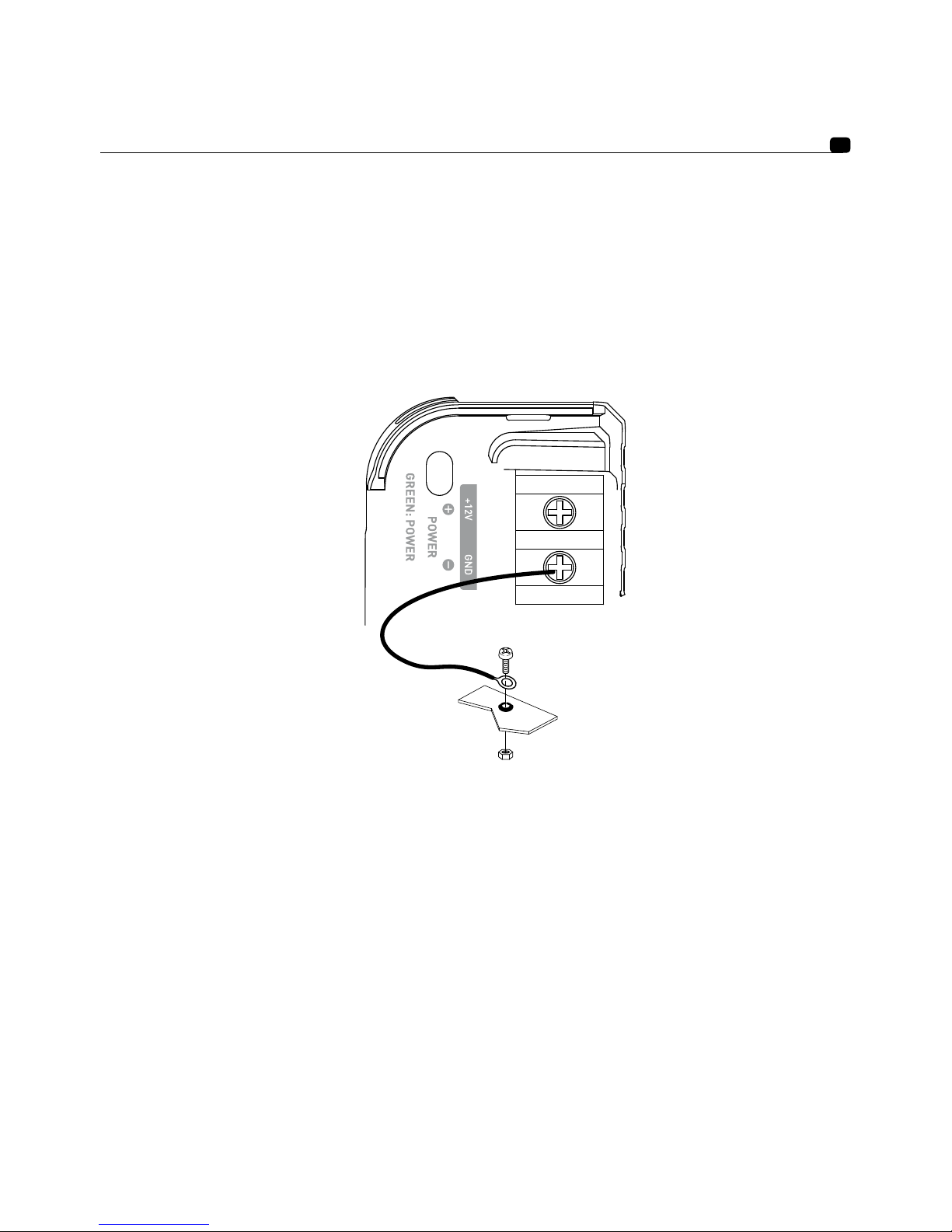
10 - Prepare the chassis ground by scraping off any trace of paint on the metal surface in order to ensure proper
grounding. The grounding connections should also be as short as possible and ALWAYS connected to metal
welded to the body or the chassis of the vehicle (fig. 2). The ground point which is generally chosen is the one
connecting the negative terminal of the battery to the chassis of the vehicle.
11 - NEVER install this equipment in the engine compartment of the vehicle. This will void the warranty.
1 - Positioning of your FD amplifier
Where to install your FD amplifier?
Due to the power of the amplifier, heat dissipation is required for correct operation. For this reason, the amplifier
must be installed in a well-ventilated area, particularly the top of the amplifier. Avoid covering or embedding the
amplifier in its installed location.
2 - Mounting your FD amplifier
Position your amplifier at the desired location and make matchmarks.
Locate the attachment points in your surface by removing the caps at each end.
Use the fixing screws supplied (adapted for wooden surfaces).
3 – Wiring your FD amplifier
WARNING
If you are uncertain of your ability to correctly install the amplifier and to wire the system properly, get a
Focal dealer/installer to do it for you.

8
FOCAL DIRECT FET® PERFORMANCE
User manual
CAUTION
Avoid routing power cables close to low-level input cables (LOW LEVEL INPUTS) and high-level input
cables (HI LEVEL INPUTS), close to the car aerial or sensitive equipment and harnesses. High-current
power cables can cause interference that affects audio signal.
CAUTION
Keep the cables as short as possible to maximise the quality of the installation. This will also limit signal
loss.
CAUTION
Before beginning the connection phase, remove the negative (-) terminal of the battery of the vehicle.
(fig.1)
3.1 - What wire gauge should I use for the power cable?
Your FD amplifier requires a power supply of adequate amperage.
The required wire gauge of power cables depends on the length of wiring to the battery. See recommended wire
gauge in the table below:
Length of cable to the battery in metres
Length < 3 m < 4 m < 5 m < 6 m < 7 m
Cross sectional
area in mm2
> 4 mm2> 5 mm2> 5 mm2> 5 mm2> 5 mm2
AWG < 11 AWG < 10 AWG < 10 AWG < 10 AWG < 10 AWG
Compliance with these wiring rules is essential for the safety of your electrical Installation and important for
maintaining maximum performance of your FD amplifier.
3.2 – Wiring the input and output signals on your FD amplifier
3.2.1 – Your head unit is equipped with RCA outputs
Route the RCA low-level wires, the speaker cables and the REM cable ensuring to insulate them from other powerful
automobile accessories, particularly electric motors (windshield wiper…). Keep the whole length of the cables, which
will be adjusted later on.
3.2.2 – Your head unit is only equipped with amplified outputs (speaker driver outputs)
Route the wires from the head unit outputs and the speaker cables ensuring to insulate them from other high-power
automobile accessories, particularly electric motors (windshield wiper…). Keep the whole length of the cables, which
will be adjusted later on.
3.3 – Wiring the power supply to your FD amplifier
3.3.1 – Route the positive power cable (+) making sure when doing so to route the cable to the opposite side of the
cables that you have previously installed – this is to avoid any interference. DO NOT CONNECT THE CABLE
YET.

9
FOCAL DIRECT FET® PERFORMANCE
User manual
3.3.2 – Get hold of the negative power cable (-). This cable should be as short as possible and ideally should not be
any longer than 1 metre, to ensure a perfect connection between the amplifier and the chassis of the vehicle. The
cable and wire gauge must comply with the table in section 3.1. Find a suitable grounding point, then sand it to re-
move any traces of paint or other coating to maximising the quality of the contact point. Drill a hole in the metal that
you have previously sanded, making a hole the same diameter as the screw you are using, making sure that there are
no fuel lines, cables or any other sensitive vehicle devices nearby. Crimp the black Y-type spade terminal supplied to
the end of the cable. Screw the black Y-type spade terminal firmly to the GND terminal on your FD amplifier (fig. 2).
Tin the other end of the cable and then crimp or solder it onto the intended spade terminal. Insert the screw through
the spade terminal, then put the screw and the nut in place and screw tight. (fig. 2)
3.4 – Connecting the input signals to your FD amplifier
You can now start the connection phase of the input/output cables.
3.4.1 – Your head unit is equipped with RCA outputs (fig. 3)
Connect the RCA cables to the amplifier. Be careful to respect the polarities (INPUT Left = black or white, INPUT
Right = red). Then connect the other end of the RCA cable(s) to the appropriate RCA* outputs of the head unit (Left
and Right).
Now connect the REMOTE cable to the amplifier (REM terminal) and screw tight. Connect the other end of the
REMOTE cable to the REMOTE terminal on the head unit. Finally, connect the speaker driver cables to the amplifier.
Be careful to respect the polarities (+ with + ; - with -) by using the red and black Y-type spade terminals supplied.
fig. 2

10
FOCAL DIRECT FET® PERFORMANCE
User manual
speaker 1
speaker 2
speaker 3
speaker 4
Remote
RCA 1/2
RCA 3/4
speaker 1
speaker 2
Remote
RCA 1/2
fig. 3.1 - FD 4.350
fig. 3.2 - FD 2.350

11
FOCAL DIRECT FET® PERFORMANCE
User manual
Minimum 2 ohms
Coil 1 -
Minimum 4 ohms
Coil 2 -
Minimum 4 ohms
Remote
Remote
RCA 1/2
RCA 1/2
fig. 3.3 bis - FD 1.350, double voice coil wiring
fig. 3.3 - FD 1.350, simple voice coil wiring
Simple voice coil speaker
Double voice coil speaker

12
FOCAL DIRECT FET® PERFORMANCE
User manual
Speaker 1 -
Minimum 4 ohms
Speaker 2 -
Minimum 4 ohms
Remote
RCA 1/2
fig. 3.3 ter - FD 1.350, speaker pair wiring
Speaker pair
CAUTION
The speaker drivers or speaker driver kits wired to your FD amplifier must have a minimum impedance of 2 Ohms.
In bridged mode (FD4.350 and FD2.350) or dual output mode (for the FD1.350), the speaker drivers or speaker driver
kits wired to your FD amplifier must have a minimum impedance of 4 Ohms.
Use of equipment with an inferior impedance will void the warranty.
3.4.2 – Your car radio is only equipped with amplified outputs (speaker driver outputs). (fig. 4)
If the head unit is not equipped with RCA outputs, a high-level output is available on your FD amplifier. Simply
connect the external transformer supplied. The number of transformers to connect depends on the number of
high-level inputs you want to use. One adapter enables you to connect 2 outputs at once (one left + one right). These
adapters will enable you to receive the input signals from the speaker driver outputs of the head unit. The conversion
is done via audio transformers isolating your amplifier from external interference. Connect the high-level adaptor
to the amplifier using the Plug and Play cable supplied. Connect the blue cable of the high-level adaptor to the REM
terminal on the amplifier. Finally, connect the speaker driver cables to the amplifier. Be careful to respect the pola-
rities (+ with + ; - with -) by using the Y-type spade terminals as shown in (fig. 3).

13
FOCAL DIRECT FET® PERFORMANCE
User manual
fig. 4.1 - FD 4.350
fig. 4.2 - FD 1.350, FD 2.350
CAUTION
The speaker drivers or speaker driver kits wired to your FD amplifier must have a minimum impedance of 2 Ohms.
In bridged mode (FD4.350 and FD2.350) or dual output mode (for the FD1.350), the speaker drivers or speaker driver
kits wired to your FD amplifier must have a minimum impedance of 4 Ohms.
Use of equipment with an inferior impedance will void the warranty.

14
FOCAL DIRECT FET® PERFORMANCE
User manual
3.6 – Wiring power supply to your FD amplifier
CAUTION
The cable connecting the positive (+) terminal of the battery to the “+ BATT” terminal of the amplifier MUST be fused
(ampere rating: 30 amperes) less than 40cm away from the battery of the vehicle.
The connections on the fuse holder must be fully insulated.
Open the fuse holder, removing the fuse with care. Fix the base of the fuse holder.
Cut a length of power cable between 10 and 40cm (maximum). Strip 1cm, then tin. Screw the cable to the terminal of
the fuse holder (battery side). Crimp the power cable to the intended spade terminal and screw to battery terminal.
Strip 1cm from the remaining length of cable, then tin. Screw the cable to the other fuse holder terminal.
40cm max
fig. 5
Prepare the positive power cable (+) to connect it to the amplifier by using the adequate Y-type spade terminal, then
block the cable by screwing tight. (fig. 5)

15
FOCAL DIRECT FET® PERFORMANCE
User manual
CAUTION
In addition to this fuse near the battery, the FD4.350 has an additional fuse which requires installation
near the amplifier.
Use the connector supplied with the fuse holder (fig. 6).
Crimp the power cable to the intended spade terminal.
fig. 6
Connect the connector to the amplifier by using the adequate spade terminal, then block the cable by screwing tight.
Insert the fuse into the fuse holder(s), and screw tight.
3.7 – Start-up and checks
The connection phase is now complete. You must now check the power supply (is correct) and that everything is wor-
king correctly (head unit/amplifier/speaker). Set the source gain to its minimum. Set the gain on your amplifier to 1/3
of the way. Turn on the different elements. Once all the elements are on, carry out a test at low volume.
CAUTION
FD4.350 is working with a particular starting sequence. It needs both REM signal and audio signal at
the input to start correctly. Please, check audiosignal presence with sufficient volume on the head unit.

16
FOCAL DIRECT FET® PERFORMANCE
User manual
4 – Control panel and connections
fig. 7.1, FD 4.350
1 11 9 1
2
3
21410 1011
4 6 5
11
8 8

17
FOCAL DIRECT FET® PERFORMANCE
User manual
2 1 19
7
1110
3 4 6 5
8 8
12
fig. 7.2, FD 2.350

18
FOCAL DIRECT FET® PERFORMANCE
User manual
2 1 19
7
1112
3 4 6 5
8 8
13
fig. 7.3, FD 1.350

19
FOCAL DIRECT FET® PERFORMANCE
User manual
1°/ INPUT(S): The RCA plugs are dedicated to the low level signal input.
2°/ GAIN: The rotary GAIN control potentiometer allows you to adjust the incoming signal to the amplifier.
CAUTION: increasing the input gain does not mean more power, but more noise. The voltage gain va-
ries between 0.2V and 5V. Optimisation of the sound system consists in applying the maximum
gain as soon as possible beforehand on the sound system and then the minimum gain afterwards.
This potentiometer must be set according to the source volume (line output level). Start by setting the amplifier
gain to its lowest level. Gradually turn up the level of the source volume up to the 3/4 of the way. Turn up the
amplifier gain level to the desired maximum listening level. Turn down the level if distortion occurs.
3°/ +12V: the power connector “+BATT” is dedicated to receive the power cable connecting the amplifier to the
positive (+) terminal of the battery.
4°/ GND: the GND (ground) power connector is dedicated to receive the negative (-) power cable connecting the
amplifier to the chassis of the vehicle.
5°/ REM : the REM connector connects the amplifier to the source (head unit via a REM or REMOTE output on the
head unit. This enables the automatic turn-on of the amplifier as soon as the source (head unit) is turned on.
6°/ SPEAKERS : the SPEAKERS connectors link the amplifier to the speaker drivers. The polarities MUST be respec-
ted (+ amplifier + crossover or + speaker driver / - amplifier - crossover or - speaker driver).
7°/ FUSES: The FUSE connector is dedicated to receive the amplifier fuse(s). In case of replacement, make sure
that the ampere rating is correct.
8°/ LEDs: the indicator LEDs enable you to check the amplifier is working correctly. A continuously illuminated
green LED means the equipment is working correctly. A continuously illuminated red LED means the equip-
ment is not working correctly. See troubleshooting section page 6.
9°/ HI LEVEL INPUT(S) : This connector is dedicated to high-level inputs (wiring on the amplified outputs of a head
unit without RCA outputs).
10°/ Crossover selector: the CROSSOVER switch enables you to choose to activate a high-pass filter (HPF), a low-
pass filter (LPF) or full range mode (FULL).
11°/ Setting the crossover cut-off frequency: This rotary potentiometer enables you to adjust the value of the high-
pass or low-pass filter. The selected value determines the frequency up to which or from which the signal will
be cut off.
12°/ Bass boost : the switch or rotary potentiometer (FD1.350 or FD2.350 respectively) enables you to increase the
volume of the bass from 0 to 12dB.
13°/ Phase : the PHASE rotary potentiometer enables you to adjust the channel phase setting according to the rest
of the installation. Adjusting the phase of the subwoofer enables the speaker driver output to be in phase or out
of phase with the other speaker drivers. On a theoretical period of a signal, one of the sources can be adjusted
slightly for the phase to be perfectly balanced at the listening point.
14°/ Mode selector: The INPUT SELECT switch (only available on the FD4.350 model) enables channels 1 and 2 to
be played through channels 3 and 4. So, if you only have one output (one right and one left), you can still amplify
the four channels by activating the 1/2 mode.

20
FOCAL DIRECT FET® PERFORMANCE
User manual
If you want to use the FD4.350 with its independent 4-channel input configuration, select mode 3/4.
If you want to use the FD4.350 in 3-channel mode, select mode 1+2. Channels 3/4 will then receive the mono signal
from channels 1 and 2 of your subwoofer.
5 – Troubleshooting
The state of the different indicator LEDs refer to the nature or the cause of a malfunction.
Check the possible causes shown below. If, despite these checks, the equipment is still not working correctly, contact
your FD amplifier installer or dealer.
Status of indicator
LEDs
Presence of sound Possible cause Action
Illuminated red NO Output short circuit Turn off the sound system
Check the speaker drivers, their
minimum impedance,
their connections and the speaker
driver cables.
Off NO No power or poor
connection
Turn off the sound system
Check power source is 12V
Check the power cables and their
polarity. Check the fuses
Flashing from red to
green
Distorted, absent
or
alternating
Overheating Turn off the sound system
Wait for your amplifier to cool down
before resuming use.
Off NO No REM signal Turn on the sound system
Check power on the REM terminal.
Off NO Fuse failure Turn off the sound system
Check and replace the fuses if
necessary.
Off / illuminated green YES/NO
Or distorted
Grounding defect Turn off the sound system
Check the continuity of your
connection from the GND terminal to
the chassis of the vehicle.
CAUTION
FD4.350 is working with a particular starting sequence. It needs both REM signal and audio signal at
the input to start correctly. Please, check audiosignal presence with sufficient volume on the head unit.
Table of contents
Languages:
Other Focal Car Amplifier manuals

Focal
Focal FP Dual Monitor User manual

Focal
Focal FP Dual Direct User manual

Focal
Focal FPP1000 User manual

Focal
Focal FP Dual Monitor User manual

Focal
Focal FP 1.800 User manual

Focal
Focal FPS 1500 User manual

Focal
Focal Power Symmetric High-Cap User manual

Focal
Focal POWER SYMMETRIC AMPLIFIERS User manual

Focal
Focal Power Symmetric User manual

Focal
Focal FPS 2300RX User manual