FOGO FH 9000 User manual

Manufacturer:
FOGO Sp. z o.o.
ul. Święciechowska 36,
Wilkowice
Święciechowa 64-115, Poland
portable
For models:
HONDA
FH3001, F3001R, FH3541, FH4001, FH4001R, FH4541,
FH6000, FH6000R, FH6540, FH6001, FH6001CRA,
FH6001R, FH6001T, FH6001TE, FH6001TR,
FH6001TRA, FH6001TRE, FH6541, FH8000,
FH8000CRA, FH8000R, FH8000T, FH8000TE,
FH8000TR, FH8000TRA, FH8000TRE, FH8220TW,
FH8220TWE,
FH8220W, FH9000, FH9000CRA, FH9000R, FH9000T,
FH9000TE, FH9000TR, FH9000TRA, FH9000TRE,
FH9220TW, FH9220TWE, FH9220W, FH9540TR,
FH9540TRA, FH9540TRE, FH9540
BRIGGS
FV10001CRA, FV10001TE, FV10001TRA,
FV10001TRE, FV10300TWE, FV10300WE,
FV11300TWE, FV11001CRA, FV11001TE,
FV11001TRA, FV11001TRE, FV13000CRA,
FV13000TE, FV13000TRA, FV13000TRE,
FV13540TRA,
13540TRE, FV15000CRA, FV15000TE,
FV15000TRA, FV15000TRE, FV15540TRA,
FV15540TRE, FV17001CRA, FV17001TRA,
FV17001TRE, FV20000CRA, FV20000TE,
FV20000TRA, FV20000TRE, FV20540TRA,
FV20540TRE
MISTUBISHI
FM6001, FM6001R, FM6001E, FM6001RE, FM8000,
FM8000R, FM8000E, FM8000RE, FM8220W,
FM8220WE, FM9000, FM9000R, FM9000E,
FM9000RE, FM9220W, FM9220WE, FM6541,
FM6541E, FM9540, FM9540RE
FOGO
F3001, F300R
User manual ORIGINAL MANUAL
Portable power generators
1
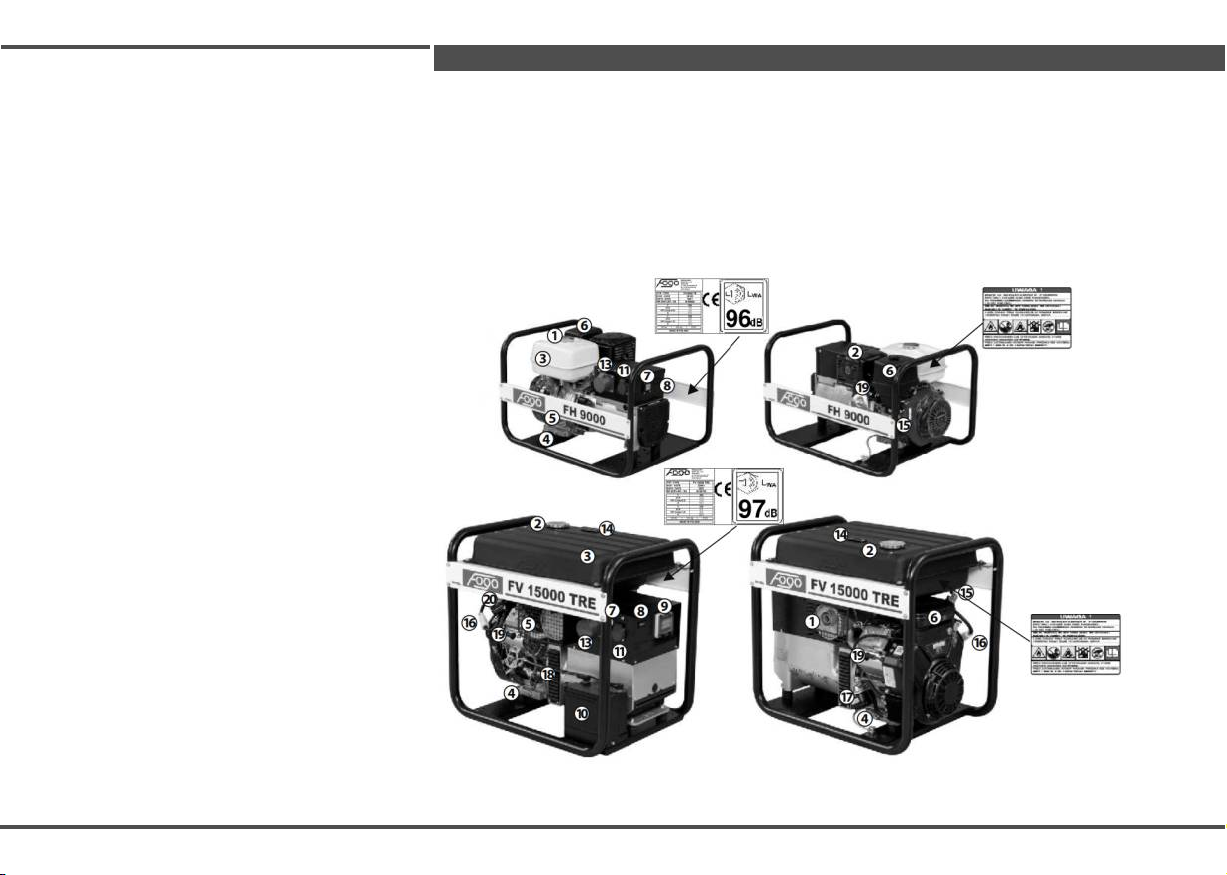
Introduction
1. Fuel filler cap
2. Silencer
3. Fuel tank
4. Oil drain plug
Location of safety and identification stickers
When using the power generator, remember to observe safety precautions. Therefore, the device is
provided with pictograms reminding about safety during operation. Their meaning is explained
below. Stickers are an integral part of the power generator. If they become illegible or destroyed,
contact your Authorized Dealer of FOGO Sp. z o.o. in order to replace them with new ones. We
strongly recommend carefully reading and understanding the safety rules included in our manual.
6
1
3
2
5. Oil dipstick
6. Air filter
7. Thermal switch
8. Operation time counter
9. Magneto-thermal circuit breaker
10. Battery
11. 230V 16A socket
12. 230V 32A socket
13. 400V 16/32A socket
14. Fuel gauge
15. Fuel valve
16. Fuel filter
17. Oil filter
5
4
2
20
16 5
19
11 17 3 6
8 19
15
14 14
3 2
15
7 8 9 1 6
13 11 19 16
18. Electric starter
19. Spark plug
20. Fuel pump
18
4
17
10
4
1
Introduction
Dear Customer
Thank you for your trust in our equipment and purchase of high-quality FOGO® power generator. We
are convinced that cooperation with world-leading manufacturers of components and application of innovative
technological solutions, we have created a product that sets standards in terms of quality, safety and reliability.
We hope that our product will meet your requirements in everyday use, ensuring long-lasting, trouble-free
operation.
FOGO Sp. z o.o.
Before the first start of the device, it is
absolutely necessary to read the manual !!
Safety of the user and all persons staying near to the device is very important. Therefore, before using
the power generator, it is essential to read these instructions. The buyer of the power generator must ensure
that this manual is always available for its operator and that every user reads the manual before starting any
activities related to device operation.
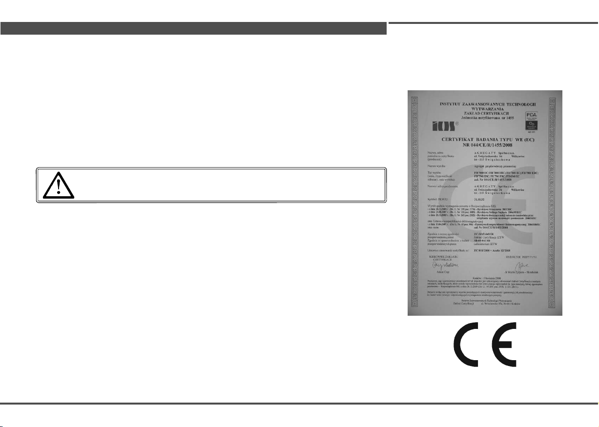
Fogo power generators are designed and manufactured in accordance with current European
directives, which we confirm by the declaration of conformity. In order to confirm that our generators meet EU
safety requirements, we submit them to additional conformity assessment procedure, performed by a third
party Notified Body.
FOGO® devices comply with the relevant European standards and other specific requirements in
terms of the construction, operational safety and environmental protection. Each power generator is provided
with CE declaration of conformity with the measuring sheet and technical specification of the unit.
2

1
Content
1. Construction of power generator................................................................................................. 4
Engine ................................................................................................................................ 4
Alternator ........................................................................................................................... 5
2. Safety rules .................................................................................................................................. 7
3. Selecting proper power generator for the receiver ................................................................... 10
4. Delivery, unloading, storage ....................................................................................................... 11
5. Disposal ....................................................................................................................................... 11
6. Operation .................................................................................................................................... 13
Starting ..................................................................................................................... 13
Stopping ................................................................................................................................... 17
7. Repair, maintenance..................................................................................................................... 19
List of maintenance operations ............................................................................................ 19
Maintenance methods ............................................................................................................ 19
Faults ................................................................................................................................. 22
8. Maintenance .............................................................................................................................. 23
List of spare parts and consumables .................................................................................... 23
Transport and storage ................................................................................................................ 24
9. General commercial terms. ........................................................................................................ 25
10. Repair log-book.......................................................................................................................... 26
11. Complaint notification card ....................................................................................................... 27
3

1
1. Construction of power generator
Power generator is a device generating
electricity by converting mechanical energy
produced by the combustion engine into
electricity produced in the alternator
connected to the engine. Power generators
are used as a source of power in case of
power failure in the network or as an
alternate power source in a building site, plot,
workshop or at home.
When operating with automatic start-up,
power generator is an excellent back-up
device for private and public buildings to
prevent uncontrolled power outages.
Technical specifications of power
generators are defined for the altitude of 0
m ASL, ambient temperature of 20°C and
60% RH. When operating in other
conditions, their performance is reduced:
for altitude - the performance decreases by
1% each 100m, for temperature - the
decrease is 2% per each 5°C. The power
generator may be adapted for permanent
use at high altitudes (above 1830 m above
sea level) by necessary modifications in
the engine introduced by an authorized
workshop.
CONSTRUCTION OF POWER GENERATOR
The power generator, in its basic version,
consists of a combustion engine
and a three- or single-phase alternator,
fixed together and installed on dampeners
in a metal frame. As a standard solution,
the power generator is equipped with
necessary protection to enable its correct
functioning, e.g. a sensor for pressure or
engine oil, two- or four-pole over-current
circuit breaker, electric starter and the
battery. The optional accessories include
working hour meter, grounding set,
transport kit, a hose for the exhaust
system, welding wires (units with a welding
module), automatic start panel with ATS
(for units with electric starter).
ENGINE
FOGO® portable generators are equipped
with four-stroke, overhead valve engines
fuelled by gasoline.
Mechanical stabilization of the engine
speed is maintained at 3000 rpm and it
operates independently of the load,
ensuring optimal parameters for
alternators. All the engines are air-cooled
and can effectively work outdoors in
ambient temperatures up to 40°C.
The engine operating indoors should be
provided with fresh air inflow of at least
100 m3/h (variable value depending on the
type of unit - for correct selection of device
and ventilation, please contact the
customer service of Agregaty S.A.).
Engines are equipped with own exhaust
systems ended with a silencer and with
compatible exhaust hoses.
The user may use one of two types of start-
up: manual with a retractable cord and
electric starter (may operate with automation
accessories). Engines with electric starter are
equipped with a system that ensures proper
charging of the battery.
SINGLE-CYLINDER (HONDA, MITSUBISHI,
RATO)
Depending on the design of the motor,
lubrication is carried out in different ways.
For single-cylinder engines it is splash
lubrication. Engines are protected against
low oil level.
Single-cylinder engines are equipped
with own fuel tanks, where fuel flows by
gravitation into the combustion chamber.
(optionally, fuel tanks may be replaced
with tanks of larger capacity).
4

1
1. Construction of power generator
Two-cylinder (BRIGGS & STRATTON-
COMMERCIAL POWER line)
In two-cylinder engines (fork-shaped), the
lubrication is carried out using pressure. The
engine has an oil pump that forces oil circulation -
when engine is stopped may cause the oil
pressure drop.
Two-cylinder engines are equipped with a
vacuum pumps for drawing fuel from external
tanks. FOGO® power generators are equipped
with two-cylinder engines are provided with tanks
of 45 litres, mounted on the frame above the
motor. All fuel tanks used in FOGO® generators
are equipped with fuel mesh filters to protect
against ingress of dust particles or other
contaminants into the carburettor.
ALTERNATOR
FOGO® generators operate with one- and
three-phase synchronous and asynchronous AC
alternators with different degrees of protection
rating (IP).
Single-phase alternators have a system of
voltage self-regulation provided by the inner
winding coupled in circuit with the capacitor. It
maintains voltage at the level of 10% with
uniform load distribution. Three-phase
alternators have a system of voltage self-
regulation at the level of 6%, and those with AVR
at the level of +/-2% at uniform load. The three-
phase alternators may operate at uneven phase
load, reaching 10 % of rated power, while the
single-phase sockets of three-phase alternators
provide up to 40% of the generator rated power.
5
For some models, it is allowed to receive power
from single-phase sockets above 40% (see
technical data). When these values are
exceeded, the electrical parameters (mainly
voltage) of the alternator may deteriorate and
windings may overheat resulting in their
burning. For single- one and three-phase
alternators, momentary overloads exceeding
10% of rated power are allowed, but they
cannot be longer than 5 minutes in every 3
hours of device operation.
Single-bearing design and the flange
connection to the engine ensure quiet and safe
operation. The drive from the engine is
transmitted through a tapered connection and
threaded rod. Alternator housing is made of
light aluminium alloys. Winding of the rotor and
stator is insulated with a special epoxy varnish
and is rated in insulation class H.
Alternators used in FOGO power generators
have the protection degree of IP 23 or IP 54.
Applying the protection degree of IP 54 extends
the life of the alternator, as the bearings and
winding are perfectly protected against harmful
impact of external factors. IP 54 increases the
range of applications in high humidity and dusty
conditions.
Synchronous alternator (IP23) - used for
inductive receivers, power tools and
construction equipment with engines of high
starting current. This alternator has windings
on the rotor and is self-excited by capacitor
that collects the remaining energy from
residual magnetization or from additional
excitation system consisting of the magnetic or
electronic regulator. Cooling of these alternators
is carried out mostly by forced air circulation in
their interior (direct cooling of windings).
Synchronous alternator IP54
Synchronous alternators in special versions are
equipped with electronic voltage regulators (AVR)
with controlled voltage and current of all three
phases. In these alternators the impact of heavily
loaded phases on the stability of a phase with a low
load is very small. AVRs ensure voltage stability of
(+/- 2%) for SDI alternator (+/- 1%). These
generators may operate at uneven phase load,
reaching 10% of rated power, while cooling is
carried out by forced air circulation in the slots
outside of the generator.
Asynchronous alternator IP54
This alternator is highly durable and transfers
no current to the moving parts through contacts,
which eliminates arcing and wearing of
brushes. The rotor has no visible windings, it
uses a cage made of steel laminations isolated
from each other with the addition of silicon.
For single- one and three-phase
alternators, momentary overloads
exceeding 10% of rated power are
allowed, but they cannot be longer
than 5 minutes in every 3 hours of
device operation.

1. Construction of power generator
The electrical circuit of the rotor is made of non-
insulated aluminium rods,
3
Ingress protection rating of IP23 or IP54
joined on both sides of the rotor with shorting
rings. Asynchronous alternator provides active
power, but consumes reactive power necessary
for magnetizing the machine. To compensate the
consumed inductive reactive power, the output of
the power generator is equipped with capacitors.
Constant speed of the alternator rotor is
maintained by the combustion engine.
First digit
Protection against foreign
objects and touch
0- without protection
1 - foreign bodies > 50 mm
2 - foreign bodies > 12 mm
3 - foreign bodies > 2.5 mm
4 - foreign bodies > 1 mm
Second digit
5 4
Protection against 6
water ingress 7
8
0 - no protection 9 11 1 2
1 - vertically falling water drops 10
2 - water dripping up to 5°
from the vertical
3 - water splashing obliquely up to6 0 °from vertical 12
4 - water spouting from all directions
Figure 1. Description of ingress protection IP symbols 3
When load changes, the speed varies only in
the range of the machine slip. It has relatively
high voltage instability at terminals of the
alternator. Some alternators have additional
windings (connected with a capacitor) to support
excitation of the generator. Cooling in these
alternators is carried out by forced air circulation
in slots outside the alternator.
4
6
safe
8
9
10.
11
12
MARKING OF THE POWER GENERATOR
2
1
13 14
DESCRIPTION OF THE NAMEPLATE
Alternator with welding module IP23
Alternators in some models are equipped with
welding modules for working with electrodes of
each type, having a diameter of max. 5 mm (FH
8220 W (TW, TWE) and 6 mm ((FV 11300
TWE, FV 11400 TWE) in the cycle of 35%, i.e.
3.5 minutes in every 10 minutes of operation.
PROTECTION CLASS IP 23 and IP 54
First digit: protection against foreign objects.
Second digit: protection against the ingress of
water.
F -
FOGO generator
Engine t ype s
H
- HONDA
V
- VANGUARD B&S
M
-
MITSUBISHI
n one
-
RATO
Engin e powe r
(~kVA)
FH 9540TRA
Protection rating
00
- IP 23
54
- IP 54
Numbe r o f pha se s
1 - single-phase (220V)
0 - three-phase (400V)
Additional options
X
- special
C
- silenced
E
- electric start
A-
prepared to connect automation
R
- AVR - Automatic Voltage Regulation
T
- enlarged tank
W
- welding module
MARKING OF THE POWER GENERATOR
NAMEPLATE
1 - CE mark confirming compliance with the
requirements of the European Directives
2 - Noise level emitted to the environment, acc. to
Directive 2000/14/EC,
3 - Name and address of the manufacturer,
4 - Model / Type,
5 - Manufacturer's code
6 - Year of production,
7 - Serial number,
8 - Nominal power [kVA],
9 - Nominal power [kW],
10 - Voltage [V],
11 - Current [A],
12 - Frequency [Hz],
13 - Weight of power generator [kg],
14 - Protection class IP 6

2. Safety rules
Safety of the user and all persons staying near to the
device is very important. Important information is
included in the manual and on the power generator set -
it must be read carefully. The information indicates and
warns of potential danger for user and third parties.
The power generator produces enough power to cause a
serious electrical shock in case of improper use. Make
sure that the power generator is grounded when
connected receivers are grounded. For grounding the
power generator, use a copper conductor with cross
section equal or larger than the conductor used to
connect receivers. If you connect the receivers having
the grounding, a grounding cable must be used.
Grounding rod is present in every Fogo generator - on
the crossbar of the frame under the engine and marked.
•
- Before starting the power generator, read its manual and make
sure that you understand all its recommendations. Every person
using the power generator must read its manual.
CAUTION ! During operation of the device,
the silencer reaches high temperatures and
remains hot for some time after stopping.
Allow the engine to cool before storing it
indoors.
•
- Do not operate the generator in an enclosed
space without sufficient ventilation. Exhaust gases
are toxic (contain large amounts of odourless
carbon monoxide [CO]) -
RISK OF POISONING OR EVEN DEATH!!!
7
During the operation, the engine should be provided
with fresh air inflow of at least 100 m³/h (variable value
depending on the type of the device - for the correct
selection of ventilation, please contact the customer
service of AGREGATY S.A.). When using the power
generator unit with additional ventilation indoors,
observe the additional requirements for explosion
protection.
- Do not fill the fuel tank while the engine is
working - RISK OF EXPLOSION!!!
- Do not start the power generator in case of
fuel spillage. Restarting is permitted after
removing of the spilled fuel - FIRE RISK!!!
- Do not run the generator in an environment with
escaping gas, paint vapours, solvents or other
combustible materials - RISK OF EXPLOSION!!!
- Do not smoke and do not use open flames near the fuel
canisters or containers RISK OF EXPLOSION!!!
- Do not operate the generator in forest areas or similar
without a spark arrester
- RISK OF FIRE!!!
- Do not operate the generator, when it is wet or damp
- RISK OF ELECTRIC SHOCK OR EVEN DEATH!!!
- Before starting the operation, check the technical
condition of the device, especially guard covers the
cable insulation.
- Do not touch the rotating parts during operation
RISK OF INJURIES OR HEALTH DAMAGE!!!
- During operation of the power generator, pay attention to
children and animals present in its vicinity
- Do not transport and do not leave the power generator
in closed rooms immediately after the operation
- RISK OF FIRE!!!
- Do not place any objects on the operating
generator. Pay attention to any objects near
the generator - its parts heat up to high
temperatures during operation - RISK OF
IGNITION!!!
- During operation, and a long time after its inactivation,
do not touch the exhaust system and silencer shields -
RISK OF BURNS!!!
- Do not operate or stop the generator under load -
RISK OF DAMAGE!!! (of the generator and the connected
receivers)
- Do not adjust the engine speed by yourself - RISK OF
ELECTRIC SHOCK OR ALTERNATOR DAMAGE!!!(failure
of alternator's winding or generating a high voltage).
- Do not fill the generator with non-compatible fluids, fuel
or with oil of inadequate quantity and quality (check oil
level daily or every 8 hours of operation, in case of oil loss -
refill with oil of the same parameters)
- RISK OF DAMAGE AND GUARANTEE LOSS!!!

2. Safety rules
- Ensure that the device is not tilted by more than 20
degrees during transport or operation. Larger tilt may
cause fuel leakage or poor engine lubrication - RISK OF
DAMAGE!!!
- Do not use non-original spare parts and fuel of unknown
origin - RISK OF DAMAGE AND GUARANTEE LOSS!!!
- After ending the operation, close the fuel tap. When the
tap is left open it may cause fuel to enter the oil pan,
reducing lubricating properties of the oil - RISK OF ENGINE
DAMAGE OR SEIZURE!!!
Do not fill the fuel during operation of the power
generator! Refuel only in well-ventilated areas. Never
unscrew the fuel cap when the engine is running or when it
is hot. If you spill fuel, move the power generator to
another place and wait before starting the engine. Fuel
must evaporate.
Read the manual.
Use safety goggles.
Use hearing protection
Any work on electrical system may only be
carried out by qualified electricians who have
the appropriate permissions SEP (Association
of Polish Electrical Engineers).
It is strictly forbidden for unauthorized
persons to work on the distribution box.
. After ending the operation, always close the fuel
valve. Avoid repeated or prolonged contact of fuel with
the skin, as well as inhalation of vapours.
DO NOT CONNECT THE POWER GENERATOR TO ANY
SOURCES OF ELECTRICITY
Connecting the power generator as a source of
emergency power supply may be made only by a
qualified licensed electrician. When connecting,
consider operational requirements of the generator in
conditions for supplying domestic networks in
accordance with applicable standards.
- Do not overload the power generator and its power
cord. Protect the power cord from heat, oil, sharp
edges and moving parts. Damage to the power cord
increases the RISK OF ELECTRIC SHOCK.
- If you work outside enclosed rooms, use extension
cords intended for use outdoors. Using suitable
extension cords reduces the RISK OF ELECTRIC SHOCK.
Using plugs and cables must not be damaged even in
the slightest degree
- RISK OF ELECTRIC SHOCK
OPERATING THE POWER GENERATOR.
The power generator is a reliable device, designed
to ensure safety. It facilitates the work and rest,
but note that there is a risk of electric shock if basic
instructions contained in the manual are not
observed.
-
Never connect the generator to the outlets in the
building.
-
Do not connect any receivers to the power
generator before starting it.
-
Do not change the internal wiring in the power
generator.
-
Never connect the three-phase sockets of the
generator to a single-phase distribution box
-
Do not adjust the rotation of the engine: current
voltage and frequency are directly dependent on
the engine speed - the adjustment is made by the
manufacturer.
-
Supply only those devices, where the voltage on the
rating plate is identical with the voltage of the
generator.
-
Protection against electric shock depends on the
fuse, which rating must be properly selected for the
model of the power generator. If the fuse needs to
be replaced, it must be replaced with a fuse having
identical rating/specifications.
-
Due to its increased resistance to mechanical
damage, a multicore cable in rubber sheathing
should be used.
-
Connect only devices in good working condition;
most of the portable electrical equipment is rated
in Class II (double insulation). Devices that do not
meet the requirements of this class (tools in a metal
housing) must be connected with a three-wire
cable.
-
Grounding of the neutral conductor of the generator
may be carried out only by a qualified electrician,
who applies an additional shock protection
measures. (PN-EN 60364-4-41).
8

2. Safety rules
-
Where the power generator is used for supplying an
existing network, e.g. at home or workshop, check
the effectiveness of electric protection used in this
network. Additional protection may be necessary
due to the low short-circuit current of the power
generator. Connecting the unit to such a network
may be only performed by a qualified and licensed
electrician.
-
Electrical cables must be carefully selected,
adjusted and serviced. Good technical
condition of t he ins ulation ensures the
safety of the user. Cables must be inspected
periodically and in case of damaging, they
must be replaced (not repaired).
-
Adjust the length and cross-section of the cable
according to the needs:
-
Depending on the cable length, there is a voltage and
current drop. We recommend the use of extension
cords with a core cross-section of 1.5mm2 or
more, and the total length not exceeding 60 m.
Observe the following rules:
-
Do not use the cables of unknown origin,
-
expand the cable completely to avoid kinks in cable
insulation,
-
use cables in accordance with the manufacturer's
instructions,
-
Power generators without AVR (Automatic Voltage
Regulation) are not designed to power sensitive
electronic equipment, e.g. TV, hi-fi equipment,
computers. These devices may not be compatible
with the power generator.
9
-
Do not overload the power generator. To ensure
proper operation and long life of the power
generator, observe the following rules:
-
total power of current receivers must not exceed
the power stated on the nameplate.
-
some current receivers (in particular electric
motors, compressors, etc.), during their start-up,
draw power greater than their rated power. For
more detailed information, contact an
authorized dealer of FOGO Sp. z o.o.
-
do not exceed the maximum power of connecting
sockets of the power generator.
-
Do not apply the nominal power to the
power generator in conditions different
than the nominal conditions. Rated power
is specified for specific operational
conditions - (atmospheric pressure of 1
bar, air temp. of 20°C, air humidity of 60%).
Power drop caused by the air temperature
or pressure drop (due to the location
altitude) may in adverse conditions exceed
10%.
-
Information on the construction of the power
generator - electrical connection. Generator
windings are not connected to the ground. As a
result, the device is safe and eliminates the risk
of electric shock. When the power generator is
used to supply power to receiving networks in
TN or TT system, it is necessary to connect the
neutral point of the generator winding to a PE
terminal and to ground
the device in accordance with PN-EN 60364-4-41
standard, as well as to provide additional shock
protection - RCD with tripping current not
exceeding 30 mA. The installation of this
equipment must be carried out by a qualified
electrician. The RCD acts as a protection against
insulation damage. It cuts off the power after
detecting insulation failure (leakage) between the
voltage line and any part of the grounding (casing)
on the output side of the RCD.
-
3-phase power generators (230/400V), single-
phase outputs (230V) are connected in parallel
with the winding in order to withstand the full
load. Power of single-phase output (230V)
indicated on the nameplate and in the technical
data is only available for these outputs under the
condition that other three-phase receivers are
not connected to the socket. Caution!!! Never
connect the three-phase sockets of the
generator to a single-phase distribution box.
When using both: single-phase 230V current and
three-phase 400V current, the current value per
phase must not exceed the value indicated on
the nameplate of the power generator.
-
Thermal or magneto-thermal circuit breaker. Power
generators are equipped with a thermal circuit
breaker, which acts as overload protection. If the
power supply is interrupted during operation, it
may be caused by automatic activation of the
thermal overload switch.

3. Selection of the power generator.
If this happens, wait for a while, eliminate the cause
of the overload, then reconnect the switch by
pressing it.
The switches are selected according to the technical
parameters of the generator; if you need to replace
them in case of damage, use only original parts of with
identical current ratings.
SELECTING PROPER POWER GENERATOR
FOR THE RECEIVER
Devices with electric motors.
Star connection - power of the power generator
may be up to 3 times higher than the rated power
of the receiver.
Delta connection - power of the power
generator may be up to 9 higher than the rated
power of the receiver.
Star / delta connection (softstart)- the power
of the generator, up to 3 times higher than the
rated power of the receiver.
With inverter, the power of the generator - up to
1.5 times higher than the rated power of the
receiver.
Commutator connections (power tools) - the
power of the generator at least 1.2 times higher
than the rated power of the receiver.
Heating equipment
Power of the generator at least 1.2 times higher
than the rated power of the receiver.
Lighting
Incandescent - power of the generator is up to
1.2 times higher than the rated power of the
heaters.
Sodium - power of the generator is up to 5 times
higher than the rated power of the bulb.
UPS
Power of the generator up to 1.7 times larger
than the power rating of connected receivers.
Electronic devices
Power of the generator at least 1.2 times larger
than the rated power of receivers.
NOTE: In order to accurately select the
power generator for the receiver, a
qualified electrician must perform
electrical measurements of the electrical
switchboard, at the start-up of the device.
Voltage of idle gear of generators is max. 253 V.
At the rated load, the voltage should not fall
below 207 V.
NOTE: Receivers sensitive to too
low or too high voltages may be
damaged when powered from
power generating sets.
ENVIRONMENTAL PROTECTION
Symbol indicating the selective
collection of waste electrical and
electronic equipment. Used
electrical appliances are secondary
raw materials
- do not dispose of them with
household waste, as they contain substances
harmful to human health and the environment!
Actively help to responsibly manage natural
resources and protect the environment by
passing the used device to the point dedicated for
used electric appliances. To reduce the waste
amount, it is necessary to reuse, recycle or
recover materials in a different form.
10.
4. Delivery, unloading, storage
For transport purposes, the power generator is
protected against the influence of weather. After
unpacking, remove the packing materials in a
way safe for the environment. Detailed
information on waste handling is defined in the
Regulation of the Minister of Economy and
Labour of 14 December 2013 - Dz.U. of 2013,
item 21.
UNLOADING
The recipient of the power generator is responsible
for its unloading and safety. To unload the power
generator, observe the general safety rules and H&S
regulations.
In particular, observe the following:
-
for unloading always use equipment dedicated for
this purpose (crane, forklift) with a suitable lifting
capacity
-
all hooks must be safely attached to dedicated
lugs - carry out unloading on a properly
hardened surface, which is suitable to withstand
the weight of the power generator and
unloading equipment.
STORAGE
When the power generator is to be stored for a
longer period, follow the basic rules:
-
store it in properly prepared room (dry and
ventilated)
-
adequately secure power generator against
dust and corrosion
-
clean the power generator from any dirt
Detailed recommendations are presented in
manuals provided by manufacturers of the engine,
alternator and other essential components.
The generator should be handled using dedicated
lugs, which form also the frame of the device.
Observe H&S regulations when handling the
power generator. In case of handling heavy loads,
it is necessary to use suitable equipment.
DISPOSAL
The purpose of disposal / recycling
is
reduced use of natural
resources and minimizing amount of
waste. According to the Waste Act of
11 September 2015 on
electrical and electronic equipment waste, term
"recycling" means a recovery, which involves re-
processing of substances or materials contained in
the waste to maximize re-use of these materials,
including minimizing of expenditures for their
processing, which protects natural resources used
for their manufacture and further processing.
CAUTION! Both the generator
and
materials used for its
construction and operation may
cause considerable damage to
the environment when
improperly disposed of. By re-
using of materials or other forms
of using old appliances, you make
an important contribution to
protecting our environment.
11

5. Disposal
CAUTION! Do not dispose the
generator and consumables at the
end of their operational life as
household waste! All waste is a
potential source of danger and
environmental pollution.
It is categorically forbidden to cause
environmental pollution by used materials or
devices. All materials must be collected, sorted,
recycled and used in accordance with the applicable
national regulations. Information on the appropriate
disposal of used devices is available from local
authorities.
After the end of the operational life of the power
generator or any of its parts, dispose them in
accordance with regulations. The following
materials must be provided to the official disposal
sites, as they may be hazardous waste. Hazardous
waste includes used objects, solids and liquids other
than wastewater, generated in households,
commercial facilities, unsuitable for the place and
time in which they have been generated and
burdensome for the environment.
It applies in particular to:
-
fluids (engine oil, coolant, etc.)
- filters
- starter batteries
- a mixture of water and antifreeze agents
-
any material soaked with operational fluids or
diesel oil
-
materials used for cleaning (e.g.
greasy, fuel-soaked or contaminated with
chemicals cleaning cloth).
-
These materials must be provided to
organisations authorised to purchase, collect
and dispose them. Do not pollute the
environment, or store the materials together
with normal household waste.
If the generator is no longer used, it must be
delivered to the organization officially involved
in disposal of industrial machinery.
The used power generator may be delivered to
the manufacturer of power generators - FOGO
company.
12

6. Operation
STARTING OF THE POWER GENERATOR
1 Fill the tank with "fresh" fuel (unleaded petrol PB
95 / 98). Refuelling must be carried out in well-
ventilated areas with the engine switched off. Do
not to smoke and do not use devices with open
flame or generating sparks in the location of
refuelling and in fuel storage areas. Do not
overfill the tank - the fuel surface must be lower
than 2 cm from the upper edge of the tank. After
each refuelling check if the container is properly
closed
2 Pour oil into the power generator, optionally - check
the oil level and refill. The oil level must be checked
when the generator stands on a level surface. To
check the condition of the oil, unscrew the filler cap
or take out the oil dipstick, wipe it, reinsert and take
out again to check the oil level on the dipstick. In the
case of a screw-cap, insert it into the hole without
screwing and check the oil level. If the level is too
low, add oil to reach the maximum level. Do not fill
oil above the maximum level mark. Use oils provided
by engine manufacturers.
Fuel level indicator (for the
aggregates with enlarged fuel tank "T"
)
Fig.2 Checking the oil level in HONDA, MITSUBISHI, RATO
engine (single-cylinder)
For power generators with Honda, Mitsubishi, Rato
engine acc. to API as SG, SF, CC or CD (SAE10W30)
Tab. 1.
Oils shown in Table may be used if the average ambient
temperature is within the indicated range.
For Briggs & Stratton "Vanguard" SE, SF, SG (SAE30)
oils may be used Tab. 2.
Depending on the temperature, for Vanguard engines
we recommend oils specified in Table 2. SAE 30 oil
used below 4°C may impact starting-up of the engine
and may cause damage to the cylinder due to
insufficient lubrication. Air cooled engines heat-up
more than liquid-cooled automotive engines. Using
synthetic multigrade oils (5W-30, 10W-30, etc.) at
temperatures above 4°C will lead to increased oil
consumption and may cause engine damage. If you use
this type of oil, it is advisable to check oil level more
frequently.
For Honda, Mitsubishi, Rato engines – use
SAE 10W30 or SAE10W40 oil, which is recommended
for general in the widest range of temperatures.
The amount of oil for each engine is indicated
in technical specifications. Do not use oils for two-
stroke engines and insoluble oils, as they affect the
life of the engine and may lead to damage.
When the amount of oil in the oil pan
MIN
MAX is insufficient or excessive, oil level or oil pressure
sensors may be activated, consequently stopping of
the engine, or preventing its start.
Fig.1 Checking oil level in a single-cylinder engine
13
Honda, Mitsubishi, Rato
Fig. 3 Checking the oil level - B&S engines (two-cylinder) Providing the engine with oil sensor
absolutely does not relieve the user from
checking the oil level every day.
Fuel filter empty full
Upper
level

+
-
6. Operation
Table 1. Selection of engine oil for HONDA, MITSUBISHI RATO
Table 2. Selection of engine oil for BRIGGS & STRATTON
3 Check the air filter for contamination/dirt. Clean,
when dirty/contaminated. Using a dirty air filter,
results in improper air-fuel ratio, causing the engine
to work unevenly, choke or to emit black exhaust gas
and finally its complete stop. This is particularly
dangerous in case of power generators, as a drop of
engine speed changes the frequency of the current
provided in the power outlet socket. Using other
forms of air filtration or using the device without the
air filter may cause device malfunction or even
serious damage (e.g. scratching the cylinder walls,
contaminating the carburettor etc.).
Do not start the engine without the air filter
installed, as it leads to quick engine wear.
4. CONNECTING THE BATTERY
(Only for engines fitted with electric starter)
The battery pack should have a nominal voltage of
12V and a capacity of at least:
- 18Ah (built-in and non-built-in single-cylinder
generators)
- 30Ah (non-built-in two-cylinder generators)
- 35Ah (-built-in two-cylinder generators).
Connecting the battery to the engine may be
performed after ensuring that this action will not
result in uncontrolled starting of the power
generator. To prevent this, the engine fuel valve
should be closed and the ignition key must be in
"STOP / 0 / OFF" position.
The cables must be connected as follows:
First, connect the terminal ("+ " red line) of the
starting device to (+) pole of the battery.
Connect terminal of "ground wire", attached to the
body of the engine or the entire housing of the
power generator, with (-) pole of the battery.
Tighten terminals firmly to prevent their loosening
during engine operation.
Make sure that the cable ends are not corroded.
Any signs of corrosion must be removed and cable
ends must be slightly greased with technical
Vaseline.
WARNING
The battery produces exploding gases,
therefore open flames, cigarettes and
spark-producing devices are prohibited
near the battery.
14
Positive (+)
cable of the
battery
Negative (-) cable of the battery

6. Operation
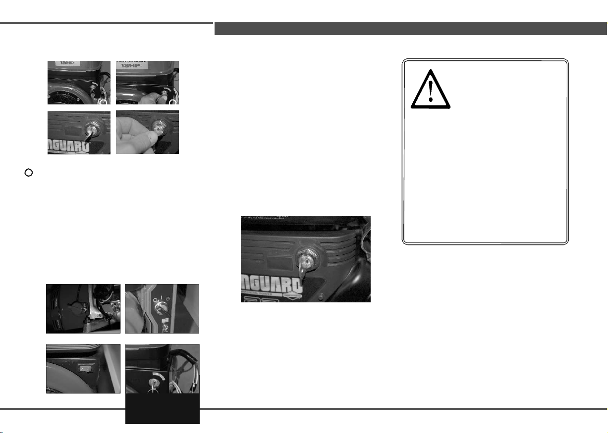
CAUTION!!! 5
Do not connect a cable
with unknown polarization.
Turn the fuel tap to "OPEN" position in power generators with the tank on the frame
CAUTION!
All engines with electric starter
are equipped with a system that ensures proper
charging of the battery. Short circuit in the
system or in connection of the battery with faulty
(reversed) polarity will automatically switch off the
engine (in Honda engines). The green indicator in
the switch indicates that the switch is turned off.
Remove the cause of switch tripping and then re-
attach it by pushing it down.
1
2
5 Turn the fuel tap to "ON"
1 2
VANGUARD
1 2
VANGUARD
in power generators with tank on the engine Set the ignition switch in ON position
"1"
HONDA / RATO
1 2
1
MIT SUBISHI
HONDA / RATO
1
2
HONDA / RATO
1
2
MIT SUBISHI
2
MIT SUBISHI
1
2
1 2
15

HONDA
2
When the engine is cold, activate choke switch, do
not use the choke when the engine is hot. When the
engine cannot stabilize its speed after start and works
unevenly, this means that the fuel-air mixture is too
rich and the choke function must be switched off.
HONDA 1 2
RATO
VANGUARD
21 HP 1
VANGUARD 1 2
31 HP
After starting the engine, do not release the cord freely,
but control its retraction by gradually releasing it. When
you release cord freely, it will be rapidly retracted by the
return spring and the handle will hit the housing.
NOTE: When the unit warmed up, it is
recommended to apply the minimum load equal
to 30% of the rated load. The power generator
should be loaded evenly in 3 phases.
HONDA 1 2
RATO
HONDA 1 2
RATO
MITSUBISHI 1 2
VANGUARD 1 2
18 HP
6. Operation
Make sure the connected receivers are
turned off or disconnect the receivers for
the start-up period.
6 MANUAL START
Pull the starter cord gently
until a slight resistance (at
this point the starter clutch
engages with the attaching
basket located placed
on the engine flywheel). Vigorously pull the cord. If
the start-up fails, repeat until it is successful. If the
starter cord is pulled by engaging clutch, this will
cause a strong collision of coupling elements with
the engaging basket, which may lead to the rupture
of the starter cord or damage of clutch
components. Pulling the cord to its end may
damage the return spring of the starter.
7 ELECTRICAL START-UP
In models with electric starter
- insert the key into the ignition and turn to (1) or ON
position
- turn the key to START position or
- after engine starts, release the key which automatically
returns to (1) or ON position and remains there during
operation of the power generator.
CAUTION!! The starter should not work for more than 5
seconds. Between consecutive start-up attempts, wait approx.
10 seconds.
NOTE: Never attempt to start the operating or not
fully stopped engine. There is risk of damage to the
starter (breaking teeth of the starter and flywheel).
When the engine is running evenly, return the choke to its
initial position. After stabilizing the engine speed, power
receivers may be activated.
HONDA 1
2
RATO
HONDA 1
2
RATO
16
1
2
6. Operation
MITSUBISHI 1
2
1
2
VANGUARD
8 STOPPING THE POWER GENERATOR
- Unplug the receiver from the socket or turn off the
receiver,
- After removing the receivers, leave the working
power generator at idling speed for 3 minutes to cool
the condenser coils.
- For power generators fuelled by petrol, set the
ignition switch in OFF position ("0"), whereas for
power generators with electric starters, turn the
ignition key to OFF position ("0").
- Close the fuel tap. For single-cylinder engines,
leaving the fuel valve open may cause fuel to
penetrate the carburettor and overflow it. Excessive
amount of fuel flows into the combustion chamber,
and from there it enters the oil sump, mixing with
oil. This mixture loses the lubricating properties,
slowly seizing the engine (connecting rod,
crankshaft, rings and cylinder). As the engine uses
splash lubrication, too high level of the oil-fuel
mixture may overflow the piston and immobilize the
engine. In such cases, remove the spark plug, drain
oil, clean the combustion chamber with compressed
air and change the oil.
VANGUARD
CAUTION! When the piston moves with the
spark plug removed, the oil accumulated
over the piston is ejected with a great force
to a considerable distance.
- If the power generator is to be stopped for
longer than 30 days, its fuel tank should be
completely emptied. Drain the fuel from the
fuel tank (not by turning the device over),
then use the remaining fuel by starting the
device and waiting for its automatic
shutdown due to lack of fuel.
- Wait until the power generator is completely cooled.
- Leave the unit in a dry, well-ventilated and roofed area
- In emergency situations requiring immediate stop of the
engine, set the ignition switch in the OFF position ("0").
- after a long stop, with fuel in the carburettor, weathered fuel
must be drained by removing the screw in the bottom part of the
float chamber (the screw is always installed at an angle)
HONDA
HONDA
MIT SUBISHI
MITSUBISHI
17

=
Table 1 Recommended diameters of welding cables
Welding current
30-100 A
100-200 A
200-300 A
15-30 m
25 mm
2
35 mm
2
50 mm
2
15-30 m
25 mm
2
50 mm
2
70 mm
2
30-60 m
35 mm
2
70 mm
2
90 mm
2
6. Operation
POWER GENERATOR WITH WELDING MODULE
DESCRIPTION OF THE CONTROL PANEL:
1. Selection of welding current
2. Selection of welding current range
3. Negative welding socket
4. Positive welding socket
CAUTION!!! Do not weld
and use the generator at the same time
To use the device as a power generator:
- Set the switch (2) to "GEN"
- Proceed as in "Starting
power generators" section
NOTE: Do not switch the welding
current switches (1 and 1a) during
welding
NOTE: During the welding, voltage is
present on the power outlet sockets, but
its voltage is low and unstable. It is recommended to
unplug the devices connected to the socket for their
safety.
NOTE: The welder may provide the maximum welding
current only for a few minutes, then it should be left to
cool down (see the table on the control panel) -
therefore if the work with high welding currents triggers
the thermal switch (welding stops, the electrode is
'sticking') let the power generator work for a few
minutes without load in order to cool it down.
Recommended diameters of welding cables:
To use the device as a welder:
- Plug the grounding cable to the socket (3)
- Connect the grounding cable to the welded
item,
- Insert the plug of the cable with the electrode
handle to the second positive socket (4).
- Set the range of welding current with switch (1 ),
(2),
- Proceed as in section "Starting the power
generator" without connected receivers.
- Start welding.
examples of welding currents:
TAB.2
Welding current
Electrodes Acidic Rutile
Cellulose
Basic
Semi-basic
1.5 mm
20-50A
20-30A
2.0 mm
40-65A
20-50A
30-60A
2.5 mm 60-110A
60-100A
50-90A
70-100A
50-80A
3.25 mm
90-150A
70-130A
70-130A
90-130A
60-100A
4.0 mm 140-
210A
120-
160A
90-170A
110-
170A
100-
140A
5.0 mm 200-
290A
190-
250A
140-
210A
175-
220A
130-
180A
18
Length

Periodic inspection /Service work
Every day
Every month
or after
first
8
hours
Every 3
months
or every 50
hours
Every 6
months
or every 100
hours
Every 12
months
or every 300
hours
Cleaning the alternator*
Checking the oil level
Oil change
**
Replacing the oil filter **
Checking the air filter *
Cleaning the air filter *
Replacing the air filter
Cleaning the spark plug
Checking and adjusting the
valve clearance ***
Adjustment of engine speed ***
Cleaning the fuel sump
Cleaning the fuel tank ***
Checking the fuel system
Every 2 years
Measuring insulation resistance
Every 6 months
7. Repair, maintenance
LIST OF SERVICE OPERATIONS
The schedule presents a list of operations performed
every day, after the first 8 hours of operation of the
device, and then subsequently every 50, 100 and 300
hours of operation.
MAINTENANCE ACTIVITIES
Cleaning and checking the alternator, each time
before starting the power generator inspect visually
connections of individual elements of the alternator,
check for damage in insulation of wires, poor
contacts, etc. In case of longer storage in
unfavourable climatic conditions, especially at high
humidity, it is recommended to measure the
insulation resistance of the alternator, using a
megohmmeter of 500 V. The insulation resistance
should be not less than 1 M Ω. If it is lower, then the
alternator's winding should be blown with dry and
warm air.
After blowing with dry and warm air, repeat the
insulation resistance measurement.
Checking oil - see section OPERATION and START-UP
Changing the oil - drain the used oil when the
engine is hot –this ensures its quick and complete
drainage. Unscrew the filler cap and the drain plug.
Drain the oil into a vessel prepared earlier.
(*) In dusty conditions the air filter and the alternator should be cleaned every day, and if necessary even at
shorter intervals.
(**) If the power generator is operated under severe conditions and in high temperatures, change oil every 25
working hours, including the oil filter.
(***) The work must be performed by an authorized servicing workshop/apartment.
CAUTION!
Use only original spare parts to ensure good quality of repair and correct operation of the
engine and alternator, enabling full guarantee of the seller. Seller (and the Guarantor)
shall not be responsible for engine damage arising from the use of spare parts that are
not original or not supplied by the Distributor.
19
This manual suits for next models
1
Table of contents
Popular Portable Generator manuals by other brands


Smarter tools
Smarter tools ST-GP6500 owner's manual

Stephill
Stephill SE6000D Handbook

Generac Power Systems
Generac Power Systems 9067-0 owner's manual

Kenwood
Kenwood TEXIO FGX-293 Series quick start guide

Mecc Alte
Mecc Alte ECO43 Series Installation, use and maintenance manual

Keysight Technologies
Keysight Technologies X Series Getting started guide

Northern Lights
Northern Lights Lugger M843NW3 Operator's manual

Pulsar
Pulsar PG4000iSR Operator's manual

Generac Power Systems
Generac Power Systems GH-410 Installation guidelines

Troy-Bilt
Troy-Bilt 1924 owner's manual

Fieldmann
Fieldmann FZI 4018 BI user manual

Briggs & Stratton
Briggs & Stratton 040248A Operator's manual