Force 12 Sigma-280 Magnum User manual
DW-Manual-Sigma-280 Magnum-001 FORCE 12 SIGMA-280Magnum Assembly Instructions Page 1 of 32
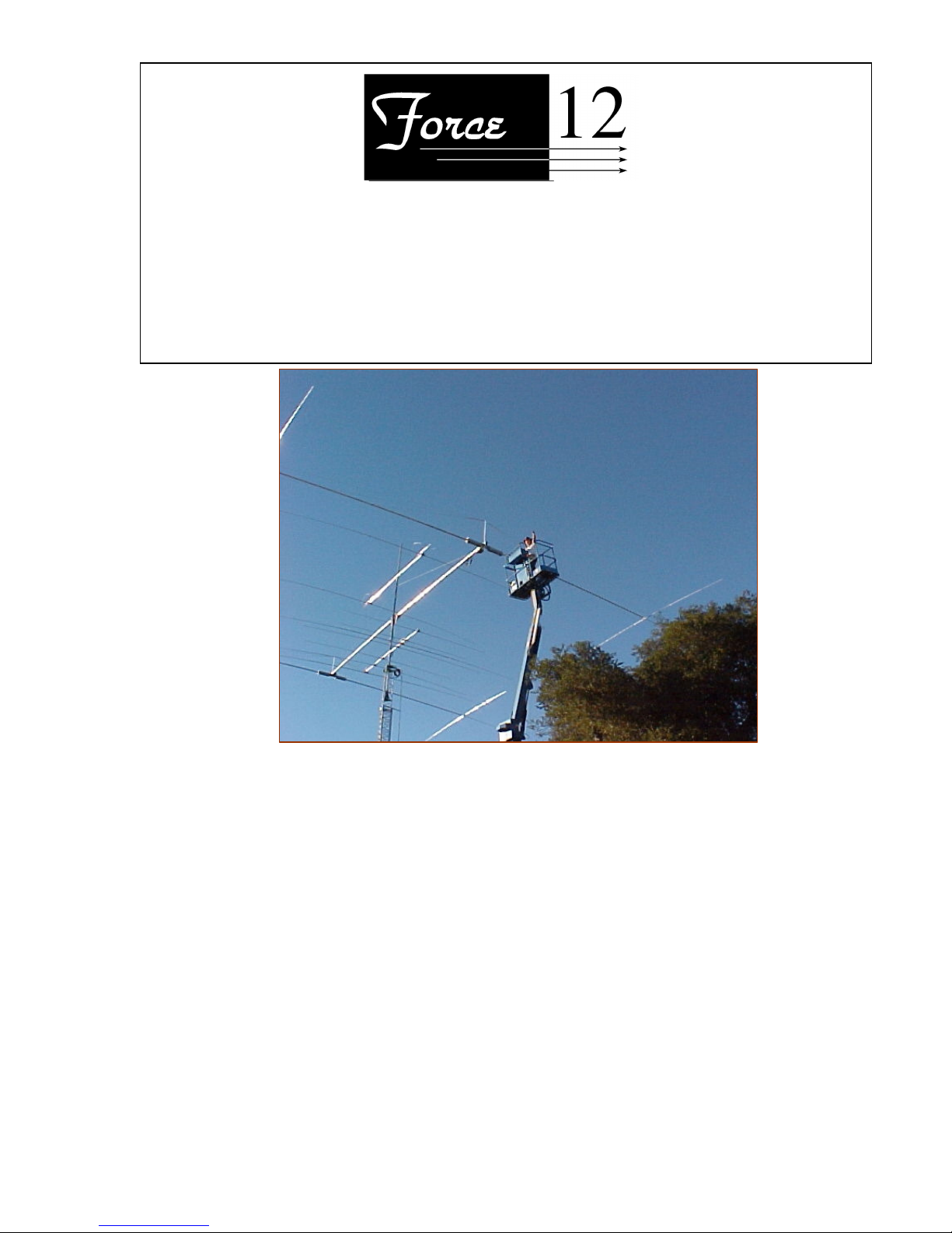
Thank you for selecting the Force 12 Sigma-280 Magnum 2 element Yagi for 80/75 meters. Released in
the summer of 2003, the Sigma-280 Magnum is another step up in the finest 80/75 meter production Yagis.
It is the product of about 9 years of development and the Sigma design is the new era in efficient antenna
design for both horizontal and vertical antennas. Thanks to the members of Team Vertical and their years
of competitive operating that eventually led to this design. Sigma-280 Magnum is composed of a pair of
Sigma-180 Magnum dipole elements. One is the driver and the other is the reflector. Other than their
tuning, they are physically identical. The function of each element is determined by the tuning of each one
and that the coax feed line goes to the driver. This manual describes building each dipole element, the
attachment to the boom of both and how to tune the antenna. Yagis for 80/75 meters are tuned much
differently than one would expect. The old theory that the reflector is tuned 3-5% lower in frequency does
not hold. The reflector is actually tuned approximately 0.7% lower.
The Sigma-280 Magnum covers several segments of the 80/75 meter band with the 2-relay external switch
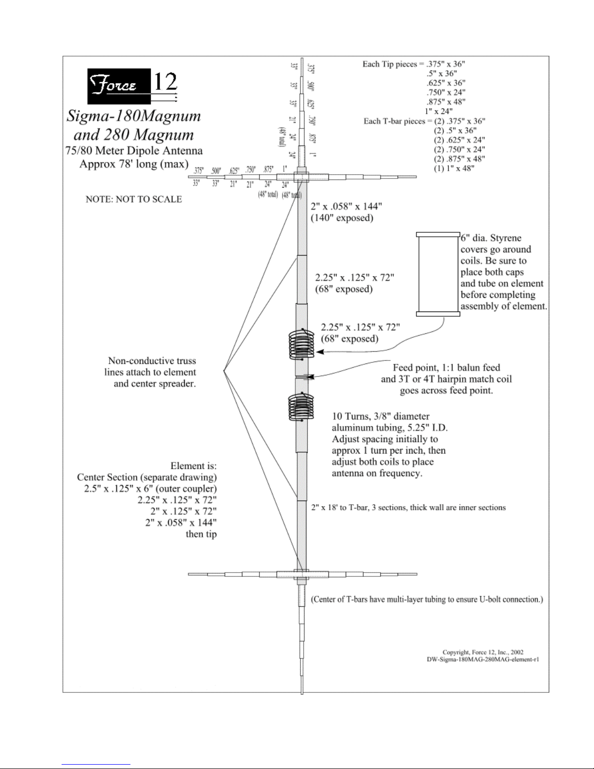
box. The antenna is composed of two elements. Each has T-bar capacitive loading about 24’ out on each
side, plus large diameter, Hi-Q coils on each side of the feed point, providing the highest efficiency of any
shortened antenna to date. The antenna is designed to present a low profile and withstand winds in excess
of 90 mph.
Sigma-280 Magnum
2 element 80/75 Meter Yagi Antenna
FREQUENCY COVERAGE: CW and Phone segments, each approximately 100 kHz 2:1 VSWR
Force 12, Inc.
P.O. Box 1293 Bridgeport, TX 76426
Technical Support and Order Line:1 940 683 8371 FAX 1.940 683 8378

DW-Manual-Sigma-280 Magnum-001 FORCE 12 SIGMA-280Magnum Assembly Instructions Page 2 of 32
The Sigma design uses elements that are about 62% mechanically full size and are made electrically full
size with end loading and center loading. The Sigma-280 Magnum elements are 76’ long. The elements are
made electrically longer by adding 26’ T-bars towards each tip for end loading. This type of loading is the
most effective and coupled with the huge center loading coils, the efficiency is 96%.
Using these efficient elements results in a 2 element Yagi with forward gain at least equal to that of 3
element Yagis utilizing mid-point coil loading and a boom of >60’. Coils with a Q as high as 600 still have
loss and the mid-point placement of the coils on the element creates a current distribution that is not as
favorable as the Sigma design. Additional disadvantages of using mid-point coils are: the potential for arc-
over at the coil (it is typically wound on a PVC core); the covering can become ineffective over time (due
to sunlight and weather); and, the structure itself (the coil form) is vulnerable to fatigue from the ever-
present wind, stress and vibration. The operating bandwidth (gain, F/B and VSWR) of the Sigma-280
Magnum is also wider than that of a coil-loaded Yagi with the same element length. This is due to the
added electrical length of the T-bars. The equivalent length of a Sigma-280 Magnum element (without the
center loading coils) is 102’.
Both elements supplied with the Sigma-280 Magnum are built the same. During assembly, one is selected
for use as the driver (the one connected to the feed line) and the other is selected as the reflector, the
parasitic element. The reflector will be tuned slightly lower in frequency than the driver and this is
accomplished by adjusting the center loading coils to the appropriate reflector frequency. The reflector is
set first, without the driver in the circuit, to the correct frequencies for phone and CW. The driver is then set
with the reflector active. Once set, the reflector is not re-adjusted, as it is pulled in frequency by the
presence of the driver. If measured by itself, the driver would resonate higher than in the 2 element Yagi,
because it is pulled down in the presence of the reflector.
The construction of the Sigma-280 Magnum elements uses all tubing. The coils are in series with each side
of the dipole and are enclosed with a large diameter styrene cover. The elements are also trussed using non-
conductive line for added strength.
The power limit for this antenna is in excess of 8KW, with the limiting factor being the balun used to feed
the driver. The next limiting factor is the 30 amp relay contacts in the CW/SSB switch box. To date, these
relays have been used in many applications for more than 10 years with no failures except for a lightening
strike. The feed point is matched to 50 ohms using a hairpin (coil) match.
The Sigma-280 Magnum is a large antenna, so care should be taken during installation. The T-bars add
another dimension, so be aware of their presence. Knowing it is possible that not everyone who has
acquired the Sigma-280 Magnum is necessarily familiar with shortened elements, it is suggested that a
good book, such as the A.R.R.L. Antenna Book be utilized for further information. Of course, one can
always proceed directly and assemble the Sigma-280 Magnum!
Feed System and Antenna VSWR
The Sigma-280 Magnum feed system is straightforward. The feed point is less than 50 ohms and is stepped
up using a simple hairpin coil across the feed point. The hairpin and balun are connected to the feed point
end of the relay box and the other end of the box is connected to the feed point terminals on the driver
element on the antenna. Since this is a balanced antenna, it should be fed through either a 1:1 balun (such
as the Force 12 B-1, B-1/C), or a suitable coaxial RF choke. The reflector element has a similar relay box in

DW-Manual-Sigma-280 Magnum-001 FORCE 12 SIGMA-280Magnum Assembly Instructions Page 3 of 32
series at the center. The far side of the box (where the balun is attached on the driver) is jumpered across
with a short wire. The relays (i.e. relay #1 in each box) in both boxes are switched simultaneously (in
parallel).
The VSWR curves for the Sigma-280 Magnum allow coverage of about 100 kHz at the 2:1 points. Adding
the flexibility of the relay box, this gives the antenna 4 segments of about this bandwidth. Two (2)
segments are normally on CW and two (2) are normally on phone; however, all four (4) segments can be
set for phone. As a short note, a low or high VSWR does not necessarily mean that an antenna works or
not. A fine book addressing this is Reflections, published by the A.R.R.L.
Each element is set to the correct operating frequency by adjusting the spacing between turns on the two,
large coils located at the center of the element. The hairpin match is adjusted for the best match (usually
1:1) on the driver at the desired frequency. The input impedance at the feed point is much less than 50
ohms (about 30 ohms) and is stepped up to 50 ohms by using the hairpin match mounted across the feed
point. This hairpin is in the form of a "helical hairpin", or coil, as a typical hairpin would be physically too
large. The match to 50 ohms is adjusted by making the spacing on the coil wider or narrower. Adjustment
at the low phone position is normally sufficient for all operating segments.
Please consult FORCE 12, Inc. for any questions.
Mechanical Overview
The mechanical design of the Sigma-280 Magnum is a pair of Sigma-180 magnum dipoles attached to a
mounting plate (weldment) on each end of the boom. The mountings are bolted to the boom using several
stainless bolts. The bolts are inserted from inside the boom, through the boom and through the mount. The
non-conductive element truss is attached to the element and to the center riser post on the element mount.
The element tubing segments are both bolted and riveted. The bolted joints are on the larger tubing and the
riveted joints are on the tips and the T-bars. The riveted element is a Force 12 “first” and identifies the
product. The antenna can be fully assembled, tuned at a reasonable height (20-25’ minimum) and then
mounted in place. Antennas always shift upwards in frequency as they are raised, so checking it at as it is
raised to a reasonable height will ensure the shift is known. If one thinks about this, having an 80/75 meter
Yagi at 25’ is like having a 20 meter Yagi at 6’ above the ground. The higher the antenna is raised to check
and verify the frequencies, the more optimum the settings. Remember that the reflector frequency is going
to be set only about 35 kHz lower than the driver. It is important to do this right!
The elements are insulated from the plates and the mast. Connection to each element is through a pair of
10-24 stainless machine screws. As previously mentioned, since this is a balanced antenna and coaxial
line is unbalanced, a means to choke off antenna current from the outside of the coax feeding the
driver element should be used. Two devices are fine: one is an RF choke, made by winding several turns
of the coax in a circle close to the feed point; or, a 1:1 balun, such as the Force 12 B-1, can be used.
Most of the hardware is stainless steel. It is type 304, not 18-8, which is only rust resistant. The plated
hardware is used for the element-to-boom bracket installation, with stainless lock washers and nuts to
enable removal. Stainless U-bolts are not necessary, except in extreme environments and a preferred
method is to paint these parts. Stainless hardware is easy to gall, meaning to freeze the nut on the shaft,
rendering the bolt useless. If all stainless is required, please contact the factory. The entire antenna can be
painted to eliminate any glint in the sun, although methods have been employed to limit glint already. For
example, the tubing is all 6061-T6, with a matte finish.

DW-Manual-Sigma-280 Magnum-001 FORCE 12 SIGMA-280Magnum Assembly Instructions Page 4 of 32
On to the assembly.............................
Tools required:
A. Wrenches or ratchets.
1. 7/16"
2. 1/2"
3. 9/16"
B. A 3/8" nut driver, or small crescent wrench for the feed point 10-24 nuts.
C. Screwdriver to back-up the 10-24 feed point machine screws.
D. Cordless drill and these bits: ¼” and 1/8” or 3/16”
E. Hand riveter, also called a "POP™", or blind riveter. These are available from the company, a local
hardware store, or possibly your dealer where this antenna was purchased. This is used to secure the
element sections together. Use the smallest nozzle (tip) for the 1/8" rivets.
F. A means to control and hoist the antenna into position.
G. Some patience and common sense - be careful, as antennas can come into contact with high voltage
lines and they are lethal. Also, be careful installing, as towers and masts are also dangerous.
Thanks
The antenna is shipped in subassemblies and each assembly section is appropriately identified. The antenna
elements are divided into two (2) halves: "A" and "B". Each tubing section has either an "A" or "B" on it
and the sections taper as they go towards the tip. Assembly requires only that the identifications are
matched. All the rivet holes are pre-drilled and will align exactly when the proper sections are matched.
The elements are identical and are split at the center. The relay boxes are placed in series with each element
at the feed point. The driver is fed with 50 ohm coax through either a 1:1 balun, or other means of a current
balun (a coaxial RF choke would be quite large). The reflector is shorted across the far end of the relay box
(the same location the balun attaches on the driver).
Please read all instructions carefully and also look at the pictures - they are truly worth a thousand words!
Assembly Notes:
1) Although the entire antenna has already been pre-assembled, it might be a good idea to double-
check the measurements, especially on the elements. Please let us know if there are any discrepancies.
Thanks.
2) When using the hand riveter, please be sure the smallest nozzle is in the tool. Sometimes with a
larger nozzle, the mandrel of the rivet can get crooked within the tool, which can result in breaking the
mandrel before the rivet is "popped." The smaller nozzle also makes a smooth finish on the rivet head.

DW-Manual-Sigma-280 Magnum-001 FORCE 12 SIGMA-280Magnum Assembly Instructions Page 5 of 32
I. First is to build the individual elements. Each one is a Sigma-180 Magnum and they are
identical. Their function is determined later by which is selected for reflector and driver, then each
element’s tuning is set.
ELEMENT ASSEMBLY
_____1) NOTE: this entire antenna has already been assembled at the factory. This is how the
holes get drilled and how the subassemblies are made. This means that every piece will
align properly, provided that they are being assembled in the right position.
_____1a) It should never be necessary to drill a hole for a rivet, or bolt.
_____1b) Each element is disassembled and separately bundled, so working with one
element at a time is the best method. This will ensure that only the parts for a
particular element are available for assembly at one time.
_____1c) Please check the measurements and the element positions to double check us at
the factory. It is rare that a marking mistake is made, but it can happen.
___2) Each element is tapered and the taper runs smaller towards the tip. Each section slides into
another and to ensure a nice fit, the larger one is crimped/swaged to reduce its size slightly.
This means that one end of each section is crimped/swaged and the reduced size of one end
can be clearly seen. Only the tip is not done in this manner, since it is the end of the element.
_____2a) Please be sure that the non-crimped/swaged end goes into the crimped/swaged end of
the larger piece.
_____2b) If the rivet holes do not align, please check to be sure the section is oriented properly
and that the correct side (A or B) is on the correct side. It should not be necessary to
drill any holes.
_____2c) Thanks.
_____3) Lay out the element assembly sections.
_____a) Side A & Side B
_____b) Note how the large Sigma coils are attached on each side of the center.
_____c) Please refer to the drawings and photos.
_____d) Be sure to slide the coil covers (tubes and caps) on before completing the assembly.
_____4) Apply Noalox compound to each of the sections that will slip into another. This can be a
thin coat, spread evenly along and around the portion that is inserted into the larger tubing.
_____5) Assemble both of the tips first.
_____a) Insert the supplied 1/8" rivets into all rivet holes. It is important to insert all the
rivets before any are pulled; otherwise, there is a possibility that the other holes
might not align properly. If at any time it becomes necessary to remove a rivet, use
an 1/8" drill and use the hole at the center of the rivet as the hole guide. Even if the
hole is enlarged, the closed-end rivets will fill in the hole when they are pulled.
_____b) Pull each rivet with the hand riveter. The mandrel of the rivet (the "shaft") is inserted
into the riveter and the handles of the riveter are squeezed. Sometimes, a complete
squeeze of the riveter will not "pop" the rivet and release the mandrel. If this occurs,
release the pressure on the riveter and push it back down over the mandrel (which
will now be sticking out farther).
_____c) Slip each section into the matching larger tubing, as in the prior step and secure with
the rivets.

DW-Manual-Sigma-280 Magnum-001 FORCE 12 SIGMA-280Magnum Assembly Instructions Page 6 of 32
_____6) Assemble both of the T-bars
_____a) Using the similar technique as above, rivet each T-bar together.
_____7) Assemble the center section of the antenna.
_____a) Refer to the drawing and photos.
_____b) Be sure to add the coil cover caps and coil cover tubes before completing the
element; otherwise, the element will have to be disassembled.
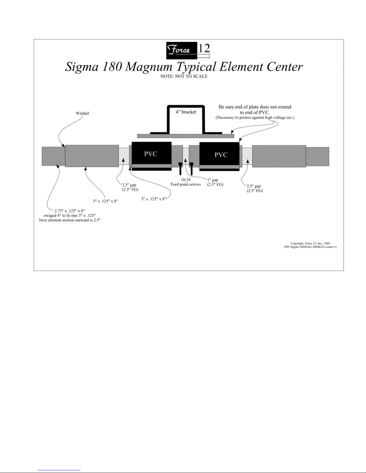
_____c) Be sure to slide the PVC insulators on the center sections.
_____1. Locate the two (2) PVC center insulators and place them over the center
portions of each element half so that each insulator is to the outside of the 10/24
machine screws used at the feed point.
_____2. The U-bolts that will be holding the element to the mounting plate are
insulated from everything by the PVC insulators.
_____d) Double check that:
_____1. the two coil cover caps are on the inside of the coils (one per side).
_____2. the covers are on each element half, to the outside of the coils.
_____3. the two coil covers for the tip ends of the covers are on the element to the tip
ends of the antenna.
_____e) Using a 1/8” or 3/16” drill bit, drill four (4) holes along a straight line on each of the
cover tubes. Start the holes about 2” in from each end of the two (2) cover tubes.
These will be the drain holes. They can be drilled later, but now is a better time.
_____f) Spread the turns on the coils for about one (1) turn per inch, or about one tubing
diameter spacing between turns.
_____f) Temporarily attach the far end (T-bar end) of each coil to the element using a 2” U-
bolt and saddle.
_____8) Complete assembly of the element
_____a) Add the remainder of the larger diameter tubing using ¼ - 20 stainless bolts and ny-
loc nuts.
_____b) Add the T-bars to the brackets using the small U-bolts and hardware.
_____c) Do not over tighten the nuts, as it is not necessary to compress the tubing.
_____d) Add the non-conductive truss line to the eye-bolts on the element. These are simply
tied to the element and the center is later clamped to the mast. Set the slack for an
attachment above the element of about 2-3’
_____9) Double check that both sides "A" and "B" have been fully assembled.
_____a) Double check that the element looks like the drawings and pictures.
_____10) The element is always installed with the rivets pointing down. This will prevent any water
from sitting in the rivets, although there is no hole actually going through them.
_____11) The element mounting plate is attached next.
_____12) If not already done, remove the saddles from two (2) of the 2” U-bolt/saddle assemblies.
_____a) Do not use the saddles.
_____b) Place the 2 U-bolts over the PVC insulators and secure to the mounting plate with `
nuts and lock washers.

DW-Manual-Sigma-280 Magnum-001 FORCE 12 SIGMA-280Magnum Assembly Instructions Page 7 of 32
_____13) With the nuts still loose on the U-bolts, align the element with:
_____a) The T-bars horizontal
_____b) The rivets on the element are pointing downward
_____c) The 10-24 feed point screws are in the correct orientation to connect to the balun /
hairpin or the optional relay box, about a 45 degree angle.
_____c1) Double check that the 10-24 feed point screws are tight (underneath the flat
washers).
_____c2) When the element mounts are attached to the boom, the feed point screws
should point towards the center of the boom (towards the mast).
_____d) The slots in the PVC insulators are in the air gap.
_____14) Now the nuts to hold the element can be tightened. It is only necessary to tighten them until
the element does not rotate with hand pressure, then about a half-turn more.
_____a) Double check that the split lock washers under the nuts are compressed.
_____15) Locate the element truss line. There are two pieces per element (one for each side/half).
_____a) If the eye-bolts are not already installed in the riser on each element mount, slide one
in from each side so that there is a loop (the eye) on each side of the riser.
_____16) Attach the center of each line to the element and run the free ends back to the center riser.
_____a) Attach each end to one of the loops, leveling the element as the line is tightened.
_____b) It is not necessary to bow the element upward (“gull wing” style).
_____c) Secure the lines at the center riser/eye-bolt.
_____17) Repeat the above procedure for the other element.
II. BOOM ASSEMBLY.
_____1) Locate all the boom sections and match up the joints (each one is engraved).
_____2) Insert the boom bolts from the top of the boom at the joints, install and tighten the nuts.
_____3) Locate the boom truss and install it in the appropriate holes. It will be held to the mast using
a single U-bolt and saddle.
_____4) Attach the elements to the boom ends.
_____a) The mounting bolts are run from the inside-out.
_____b) Start with the back bolts (farthest inside the boom).
_____c) Slide the bolt through the boom, then through the element mounting bracket
and add the split lock washer and nut, but do not tighten fully yet
_____d) After all the bolts are in and the nuts are started, tighten all the nuts.

DW-Manual-Sigma-280 Magnum-001 FORCE 12 SIGMA-280Magnum Assembly Instructions Page 8 of 32
III. SIGMA-280 MAGNUM TUNING.
_____1) The antenna will shift upwards as it is raised; however, it should not move more than 30
kHz up to a height of 70 feet when adjusted at a height of 20'. It is a good idea to make notes
on the shift as the reflector is tuned and raised. The reflector is tuned first and this will make
the driver simpler, as the shift will be known.
_____2) Please refer to the photo pages.
_____3) Use the U-bolts and saddles to secure the far end of the coils for initial tuning.
_____a) If it can be tuned at about 25-30' high, it should move only about 10 kHz
when raised to 75-90' high.
_____b) Increasing the spacing between turns on the two coils decreases the
loading and will raise the frequency.
_____c) Decreasing the spacing between turns on the 2 coils increases the loading and
will lower the frequency.
_____d) After securing the coils with the U-bolts, fine tuning can be done by
squeezing the turns together, or expanding them. After tuning, the coils are attached
permanently by drilling through the flat coil end and the boom, securing with ¼-20
hardware. The U-bolt and saddle can then be removed from each coil.
_____4) While tuning, tape the covers and end caps to the element to prevent them from sliding out
of reach.
_____5) If not already done, attach both elements to the boom and designate one as the driver and the
other as the reflector. The direction of maximum energy will be from the reflector, towards
and through the driver.
_____6) The boom truss can be attached to the mast after the antenna is tuned and mounted on the
mast.
_____7) Attach both relay boxes in parallel using the supplied 5-conductor wire. Only 4 conductors
are needed. Break the wire at the center for the supply and control line, then connect the
supply/control line and both cables to the boxes in parallel. Dress the leads to the boom.
_____8) Connect a relay box to the element feed point on each element using the supplied (2) wires.
_____a) This connection is the “up” end of the box, when the barrier strip is on the bottom
right of the box and the hinge is on the left side.
_____b) Position the box so that the hinged door will be on the bottom when the relay box is
attached to the boom.
_____9) Secure the boxes to the boom using the tie-wraps through the ears at the box corners. The
ears should be positioned for the best locating of the tie-wraps to the boom. Solid, stiff wire can also
be used to secure the boxes to the boom.
_____10) The reflector element is tuned first.

DW-Manual-Sigma-280 Magnum-001 FORCE 12 SIGMA-280Magnum Assembly Instructions Page 9 of 32
_____11) Attach a balun and coax feed line to the feed point end of the relay box on the reflector.
_____12) Leave the feed point of the driver element open – if this is not done, all tuning will be
fruitless. The driver will be coupling to the reflector and the reflector will not be set on the proper
frequencies.
_____13) A VSWR meter of some type that is accurate is needed for tuning purposes. If using an MFJ,
read only the left-hand (VSWR) meter and ignore the readings on the right-hand meter.
_____14) Energize the CW/Phone relay (relay #2, the one with larger coils). If the antenna was
ordered with an optional third relay to open the elements, energize it as well; otherwise, the element
is not in the circuit. With 3 relays, the CW/Phone relay is #3.
_____15) With the antenna at a reasonable height, read the frequency of lowest VSWR on the
reflector. This is the LOW PHONE position.
_____16) The target frequency is 25-30 kHz below the intended operating frequency, so if the DX
window at 3790-3795 is wanted, the reflector should be set for 3760-3765. This is the reflector
frequency for maximum F/B ratio on the desired driver frequency (i.e. 3.790-3.795). If wider
bandwidth is desired, such as working down to 3.750 for the JA window, the reflector should be
tuned lower to about 3.750. The F/B in the window will be a bit less, but the operating bandwidth
will be much wider. The VSWR curve for the antenna (both elements active) will rise sharper on
the low side and slowly on the high side.
_____17) If the frequency is low, spread the coils on both sides of the center, trying to keep them
equal (not absolutely critical for them to be exact). If the U-bolts and saddles securing the far end of
the coils need to be moved, go ahead and move them.
_____18) If the frequency is high, compress the coils, moving the U-bolts and saddles if needed.
_____19) After setting this frequency, open the CW/Phone relay and read the frequency.
_____20) The frequency should be set for 25-30 kHz lower than the target frequency of, say 3.505.
Adjust the coils on both sides of the relay (not the large coils already set) for the desired frequency
(i.e. 3.505 – 25 = 3.480). The coils will always be expanded to reach this frequency.
_____21) Remove the balun and feed line from the reflector relay box and short out the feed point
using the supplied copper jumper (about 2-3” long).
_____a) Secure the cover on the relay box.
_____22) Secure the coils in position, if not done so already.
_____a) Be sure the U-bolt is tight and the coil is in position for proper tuning.
_____b) Use a ¼” drill and drill through the tip end of the coil (flattened end) and
through the element.
_____c) Use a ¼ - 20 bolt and ny-loc to secure the coil.
_____23) Secure the covers.

DW-Manual-Sigma-280 Magnum-001 FORCE 12 SIGMA-280Magnum Assembly Instructions Page 10 of 32
_____a) Slide both covers over the coils.
_____b) Slide the end caps over both of the covers, being sure not to disturb the coil
spacing.
_____c) If the cover drain holes were not drilled earlier, drill four (4) drain holes in a
straight line in what will be the bottom of the coil covers. Use a 1/8” or 3/16”
drill bit.
_____d) Rotate the drain holes so that they are down.
_____e) Use a good quality silicone sealant (RTV) and run a bead along the caps in
two (2) places:
_____e1. Around the hole where the element goes through each cap
_____e2. Around each cap where the cover enters the cap.
_____f) The caps and covers can be painted if desired.
_____24) The driver is tuned next.
_____25) Be sure the relay boxes on both elements are operating in tandem.
_____26) Using the same basic procedure as on the reflector, tune the driver.
_____27) Attach the actual balun, feed line and matching hairpin to the driver feed point on the relay
box.
_____a) Set the initial spacing on the hairpin coil about ¾” between turns.
_____28) Energize the CW/Phone relays for LOW PHONE.
_____29) Tune the coils on the driver for a frequency of 3.790-3.795 and secure the far ends as before,
then secure the coil covers.
_____30) Adjust the hairpin match for the lowest VSWR.
_____31) Open the CW/Phone relay and adjust the coils on the relay for the operating frequency (i.e.
3505).
_____a) Secure the cover on the relay box.
_____32) Secure the coils in position, if not done so already.
_____a) Be sure the U-bolt is tight and the coil is in position for proper tuning.
_____b) Use a ¼” drill and drill through the tip end of the coil (flattened end) and
through the element.
_____c) Use a ¼ - 20 bolt and ny-loc to secure the coil.
_____33) Secure the covers.
_____a) Slide both covers over the coils.
_____b) Slide the end caps over both of the covers, being sure not to disturb the coil
spacing.
_____c) If the cover drain holes were not drilled earlier, drill four (4) drain holes in a
straight line in what will be the bottom of the coil covers. Use a 1/8” or 3/16”
drill bit.
_____d) Rotate the drain holes so that they are down.

DW-Manual-Sigma-280 Magnum-001 FORCE 12 SIGMA-280Magnum Assembly Instructions Page 11 of 32
_____e) Use a good quality silicone sealant (RTV) and run a bead along the caps in
two (2) places:
_____e1. Around the hole where the element goes through each cap
_____e2. Around each cap where the cover enters the cap.
_____f) The caps and covers can be painted if desired.
IV. MOUNTING TO THE MAST
_____0) NOTE: in most installations, this antenna should be mounted parallel to the booms of
other antennas on the mast, especially 20 meter antennas, as it probably will significantly affect
them. Make a chart of the VSWR curves of the existing antennas and check them after installation of
this antenna to be sure there is no severe interaction.
_____1) The antenna needs to have several feet above the antenna to make room for the boom truss
attachment.
_____a) The antenna is mounted using a drop-in cradle mount that is first mounted to the
mast by several U-bolts and saddles.
_____b) Note that the cradle mount has holes drilled through it for bolts going through the
boom. The boom is not drilled until the antenna is actually installed. This makes sure the
elements are parallel to the ground and that the antenna is balanced with the coax and balun.
_____2) Carefully lower the antenna into the cradle. Be sure to watch for the relay box control lines
and the coax feed line.
_____3) Center the antenna for balance, align the elements so they are parallel to the ground and drill
through the boom.
_____a) Use the holes in the cradle for a guide (the holes centered on the boom).
_____b) Drill from both sides, not only one side – it is not possible to hit the far side hole.
_____c) Slide the boom bolts through the cradle and boom. Secure with nuts.
_____4) Open up another U-bolt and saddle, pass the truss line under the U-bolt (not under the saddle
that has sharp edges), add the saddle behind the mast and secure with the nuts and lock
washers.
_____a) Slide the truss upward to tension the truss so that the boom is almost horizontal.
_____5) Check the antenna for resonance at the desired frequency to be sure nothing moved.
Checking now is better than later!
_____6) Check the VSWR on other antennas in the area (i.e. on the mast) to be sure this antenna has
not de-tuned them. If the VSWR has not changed, the interaction is minimal, but the
front-to-back ratio of the other antenna(s) might have been lessened. This antenna can be
mounted parallel to the other booms for the least interaction potential. It has been
specifically designed for high reactance with other bands; however, coupling can still occur.

DW-Manual-Sigma-280 Magnum-001 FORCE 12 SIGMA-280Magnum Assembly Instructions Page 12 of 32
III. FINAL CHECKOUT
_____1) Apply power and have fun.
Notice...........................................
PLEASE BE CAREFUL AND DO NOT LET THIS ANTENNA COME INTO
CONTACT WITH POWER LINES OR OTHER DANGERS. YOU CAN BE
INJURED OR KILLED BY IMPROPER HANDLING OF THIS ANTENNA.
Thank you for selecting our product. We hope you enjoy using it.
Force 12, Inc. Warranty, Limitation of Liability
Force 12, Inc. products are warranted for a period of one year from date of purchase. Warranty covers defects in manufacturing and workmanship. Force 12,
Inc. has the discretion of honoring the warranty if the product appears to have been abused, used in a manner that exceeds the specifications of the unit, or a
use for which the product was not designed. This warranty does not cover transportation, installation, punitive, or other costs that may be incurred from
warranty repair, or installation Force 12, Inc. must be notified and warranty repair authorized (only by Force 12, Inc. who issues an RMA) before the
company will accept any product returns. Please advise the date of purchase, model number, serial number (if applicable) and a brief description of the
problem. 30% restocking fee on products returned unused with RMA issued by Force 12, Inc. at the sole discretion of Force 12, Inc.
The customer, installer and user of these products individually and collectively acknowledge that these products can cause injury or death and individually
and collectively accept full responsibility and liability for any and all personal and property damage (direct, indirect and punitive) caused during installation
and/or use of these products and hold Force 12, Inc. harmless for such damage. (warranty notice date 10/15/2004)
DW-Manual-Sigma-280 Magnum-001 FORCE 12 SIGMA-280Magnum Assembly Instructions Page 13 of 32
DW-Manual-Sigma-280 Magnum-001 FORCE 12 SIGMA-280Magnum Assembly Instructions Page 14 of 32

DW-Manual-Sigma-280 Magnum-001 FORCE 12 SIGMA-280Magnum Assembly Instructions Page 15 of 32

DW-Manual-Sigma-280 Magnum-001 FORCE 12 SIGMA-280Magnum Assembly Instructions Page 16 of 32
DW-Manual-Sigma-280 Magnum-001 FORCE 12 SIGMA-280Magnum Assembly Instructions Page 17 of 32
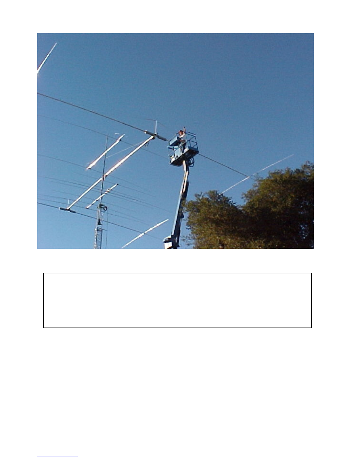
Sigma-280 Magnum at WA5VGI

DW-Manual-Sigma-280 Magnum-001 FORCE 12 SIGMA-280Magnum Assembly Instructions Page 18 of 32
End of coil secured with ¼-20 bolt.
Note cap is already on at the center.
The tube and outer cap are already positioned on the element, as well.

DW-Manual-Sigma-280 Magnum-001 FORCE 12 SIGMA-280Magnum Assembly Instructions Page 19 of 32
Coil cover – tube and caps.
Note: the through bolts on
this mounting bracket were
for a proto-type only. The
actual go from the inside-
out.

ERROR: undefined
OFFENDING COMMAND: f‘~
STACK:
Table of contents
Popular Antenna manuals by other brands

Televes
Televes DATBOSSMIX LR quick start guide

König Electronic
König Electronic KN-DVBT-OUT111 manual

Panorama Antennas
Panorama Antennas FIND4/GPS D4/SHK 4 Series installation instructions

Chameleon Antenna
Chameleon Antenna CHA LEFS 4010 Operator's manual

Sirius Satellite Radio
Sirius Satellite Radio FEA FM Extender Antenna installation guide

DX Antenna
DX Antenna DTA3500 instruction manual


Hypercable
Hypercable Z24A60T37301 installation instructions

Panasonic
Panasonic Ramsa WX-RP921 operating instructions

Gogen
Gogen DA184 user manual

CUSHCRAFT
CUSHCRAFT A4S Assembly and installation instructions

Panorama Antennas
Panorama Antennas WMM48G-17-42 isntallation instructions

Maxview
Maxview MXR0052 Assembly instructions