Forma Scientific 8500 Series User manual

Forma Scientific, Inc.
P.O. Box 649
Marietta, Ohio 45750
Telephone: (740) 373-4763
Telefax: (740) 373-2382
________________________________________
Models:
8516, 8517, 8523, 8525,
8526, and 8560
8500 Series Non-CFC
Ultra-Low Temperature Upright Freezers
Manual No. 7028516 Rev. 2
Read this Instruction Manual.
Failure to read, understand and follow the instructions in this manual may result
in damage to the unit, injury to operating personnel and poor equipment performance.
Caution: All internal adjustments and maintenance must be performed by
qualified service personnel.
Refer to the serial tag on the
rear cover of this manual

Forma Scientific, Inc.___________________________________________________Service
ii
The material in this manual is for information purposes only. The contents and the product it
describes are subject to change without notice. Forma Scientific Inc. makes no representations or
warranties with respect to this manual. In no event shall Forma Scientific Inc. be held liable for
any damages, direct or incidental, arising out of or related to the use of this manual.
This product is not intended for any use(s) other than the use(s) in the labeling or this user’s
manual.
MANUAL NO. 7028516
-- 18249/SI-7545 7/7/99 Added P/N 195517 air filter kit to parts list ccp
-- -- 10/30/98 Added battery replacement time to Section 3.3/ Ed Dutton ccp
-- 16484 9/1/98 Add caution to section 6.7 re: rechargeable type batteries deg
-- FR-1203 5/26/98 Added metric units to ref. drawing for IEC-1010 deg
-- -- 1//20/98 Added “Climatic Class T” to Section 2.2 deg
-- SI-6703 1/5/98 Revised electrical schematics heg
2 see description 11/21/97 Revised per FR-1145, FR-1146, FR-1160 and SI-6706 heg
REV ECR/ECN DATE DESCRIPTION

Forma Scientific, Inc.___________________________________________________Service
iii
Do You Need Inform ation orAssistance on Form a Scientific
Products?
do,please contactus 8:00 a.m .to 7 :0 0 p .m.(E a s tern Time)at:
1-740-373-4763 D ire c t
1-888-213-1790 TollFree,U.S.and C anada
1-740-373-4189 FAX
http ://www.form a.com InternetWorldw ide WebH om e Page
fservice@ form a.com Service E-M ailAddress
If you
Forma's can provide information on pricing and give you quotations. We
can take your order and provide delivery information on major equipment items or make
arrangements to have your local sales representative contact you. Our products are listed on the
Internet and we can be contacted through our Internet home page.
The Forma can supply technical information about proper
setup, operation or troubleshooting of your equipment. We can fill your needs for spare or
replacement parts or provide you with on-site service. We can also provide you with a quotation
on our Extended Warranty for your Forma products.
Whatever Forma products you need or use, we will be happy to discuss your applications.
If you are experiencing technical problems, working together, we will help you locate the
problem and, chances are, correct it yourself...over the telephone without a service call.
When more extensive service is necessary, we will assist you with direct factory trained
technicians or a qualified service organization for on-the-spot repair. If your service need is
covered by the Forma warranty, we will arrange for the unit to be repaired at our expense and to
your satisfaction.
Regardless of your needs, Forma's professional telephone technicians are available to
assist you Monday through Friday from 8:00 a.m. to 7:00 p.m. Eastern Time. Please contact us
by telephone or fax. If you wish to write, our mailing address is:
Forma Scientific, Inc.
PO Box 649
Marietta, OH 45750
International customers please contact your local Forma Scientific distributor.
Sales Support
Product Service Support

Forma Scientific, Inc.____________________________________________________Safety
iv
General Safety Notes used in this Manual
Important operating and/or maintenance instructions. Read the accompanying text
carefully.
Ce symbole attire l’attention de l’utilisateur sur des instructions importantes de
fonctionnement et/ou d’entretien. Il peut être utilisé seul ou avec d’autres symboles
de sécurité. Lire attentivement le texte d’accompagnement.
Wichtige Betriebs- und/oder Wartungshinweise. Lesen Sie den nachfolgenden
Text sorgfältig.
Importante instruccions de operacion y/o mantenimiento. Lea el texto
acompanante cuidadosamente.
Potential electrical hazards. Only qualified persons should perform procedures
associated with this symbol.
Ce symbole attire l’attention de l’utilisateur sur des risques électriques potentiels.
Seules des personnes qualifiées doivent appliquer les instructions et les procédures
associées à ce symbole.
Gefahr von Stromschlägen. Nur qualifizierte Personen sollten die Tätigkeiten
ausführen, die mit diesem Symbol bezeichnet sind.
Potencial de riesgos electricos. Solo personas das capacitadadas deben ejecutar
los procedimientos asociadas con este simbulo.

Forma Scientific, Inc.____________________________________________________Safety
v
Equipment being maintained or serviced must be turned off and locked off to
prevent possible injury.
Risques potentiels liés à l’énergie. L’équipement en entretien ou en maintenance
doit être éteint et mis sous clé pour éviter des blessures possibles.
Geräte, an denen Wartungs- oder Servicearbeiten durchgeführt werden, müssen
abgeschaltet und abgeschlossen werden, um Verletzungen zu vermeiden.
El equipo recibiendo servicio o mantenimiento debe ser apagado y segurado para
prevenir danos.
Hot surface(s) present which may cause burns to unprotected skin or to materials
which may be damaged by elevated temperatures
Présence de surface(s) chaude(s) pouvant causer des brûlures sur la peau non
protégée, ou sur des matières pouvant être endommagées par des températures
élevées.
Heiße Oberfläche(n) können ungeschützter Haut Verbrennungen zufügen oder
Schäden an Materialien verursachen, die nicht hitzebeständig sind.
Superficias calientes que pueden causar quemaduras a piel sin proteccion o a
materiales que pueden estar danados por elevadas temperaturas.
√
√√
√Always use the proper protective equipment (clothing, gloves, goggles etc.).
√
√√
√Always dissipate extreme cold or heat and wear protective clothing.
√
√√
√Always follow good hygiene practices.
√
√√
√Each individual is responsible for his or her own safety.

Forma Scientific, Inc.__________________________________________________Contents
vi
Table of Contents
Section 1 - Receiving
1.1 Preliminary Inspection..........................................................................1-1
1.2 Visible Loss or Damage........................................................................1-1
1.3 Responsibility for Shipping Damage.....................................................1-1
Section 2 - installation
2.1 Introduction .........................................................................................2-1
a. Enviro-Scan Microprocessor Monitoring System.........................2-1
b. Non-CFC, non-HCFC and Non-flammable Refrigerants..............2-1
c. Peak Control System....................................................................2-1
d. "Smart" Condenser Fans..............................................................2-2
e. Built-In Automatic Voltage Compensation ..................................2-2
2.2 Environmental Conditions ....................................................................2-2
2.3 Installing the Wall Bumpers..................................................................2-3
2.4 Location................................................................................................2-3
2.5 Connecting the Water Supply to the (optional)
Water Cooled Condenser ...............................................................2-3
2.6 Attaching the Power Cord Set...............................................................2-4
2.7 Connecting Power to the Freezer ..........................................................2-4
2.8 Deactivating the Enviro-Scan Monitor for Storage................................2-4
2.9 RS-232 Output Interface.......................................................................2-5
2.10 Remote Alarm Connector...................................................................2-6
Section 3 - Enviro-Scan Monitor
3.1 The Enviro-Scan Monitor ....................................................................3-1
3.2 Main Power Switch (Mains Disconnect)..............................................3-2
3.3 Key Functions Requiring No Access Code...........................................3-2
a. Access Keys...................................................................................3-3

Forma Scientific, Inc.__________________________________________________Contents
vii
3.4 Key Functions Requiring Access Code ................................................3-3
a. Set Point Adjustment Screw..........................................................3-4
3.5 Audible Alarm and Control Panel Indicators........................................3-4
3.6 Double Door Freezer (Factory-Built Option) .......................................3-6
3.7 Set Point Adjustment Screwdriver .......................................................3-6
3.8 Automatic Voltage Compensation System ...........................................3-6
3.9 CoBex Temperature Recorder (optional)..............................................3-7
Section 4 - Start-up
4.1 Setting the Operating Temperature.......................................................4-1
4.2 Setting the Low and High Limit Set Points ..........................................4-1
a. To display or change the Low Limit Set Point...............................4-1
b. To display or change the High Limit Set Point..............................4-2
4.3 General Recommendations ..................................................................4-2
4.4 Preparing the (Optional) CoBex Temperature Recorder.......................4-2
a. Installing the chart recorder battery..............................................4-2
b. Installing the chart paper .............................................................4-3
c. Changing the recorder range ........................................................4-3
d. Calibrating the chart recorder ......................................................4-4
e. Recorder outlet ............................................................................4-4
Section 5 - Calibration
5.1 Calibration...........................................................................................5-1
5.2 Calibrating the Temperature Alarm Monitor Probe..............................5-1
5.3 Calibrating the Control Set Point Temperature Probe ..........................5-2
5.4 Changing the Access Code...................................................................5-3
Section 6 - Routine Maintenance
6.1 Cleaning the Cabinet Exterior...............................................................6-1
6.2 Cleaning the Condenser ........................................................................6-1
6.3 Cleaning the Air Filter..........................................................................6-2
6.4 Defrosting the Chamber........................................................................6-2
6.5 Cleaning the Door Gasket.....................................................................6-3
6.6 Cleaning the Vacuum Relief Port..........................................................6-3
6.7 Replacing the Performance Monitor/Alarm Battery ...............................6-4

Forma Scientific, Inc.__________________________________________________Contents
viii
Section 7 - Service
7.1 Servicing the Refrigeration System.......................................................7-1
7.2 Troubleshooting Guide .........................................................................7-1
7.3 8500 Upright Series Cabinet Hardware.................................................7-1
Section 8 - Specifications
8.1 Models 8516 and 8517..........................................................................8-1
8.2 Model 8523...........................................................................................8-2
8.3 Models 8525 and 8526..........................................................................8-3
8.4 Model 8560...........................................................................................8-4
Section 9 - Spare Parts
Section 10 - Refrigeration Drawings
Section 11 - Electrical Schematics
Section 12 - Supplements and Warranty information

Forma Scientific, Inc._________________________________________________Receiving
1-1
Section 1 - Receiving
1.1 Preliminary Inspection
This item was thoroughly inspected and carefully packed prior to shipment and all
necessary precautions were taken to ensure safe arrival of the merchandise at its destination.
Immediately upon receipt, before the unit is moved from the receiving area, carefully
examine the shipment for loss or damage. Unpack the shipment and inspect both interior and
exterior for any in-transit damage.
1.2 Visible Loss or Damage
If any loss or damage is discovered, note any discrepancies on the delivery receipt.
Failure to adequately describe such evidence of loss or damage may result in the carrier
refusing to honor a damage claim. Immediately call the delivering carrier and request that
their representative perform an inspection. Do not discard any of the packing material and
under no circumstances move the shipment from the receiving area.
1.3 Responsibility for Shipping Damage
For products shipped F.O.B. Marietta, Ohio, the responsibility of Forma Scientific,
Inc. ends when the merchandise is loaded onto the carrier's vehicle.
On F.O.B. Destination shipments, Forma Scientific's and the carrier's responsibility
ends when your Receiving Department personnel sign a free and clear delivery receipt.
Whenever possible, Forma Scientific, Inc. will assist in settling claims for loss or
in-transit damage.

Forma Scientific, Inc.________________________________________________Installation
2-1
Section 2 - Installation
2.1 Introduction
The 8500 Series Forma Scientific non-CFC, Ultra-Low Temperature Freezers
feature front-to-back air circulation for cooler compressor temperatures, increased
performance and reliability and longer compressor life. In this unique system, ambient air
enters the front grill of the freezer and passes through the filter, condenser and compressor
housing, exiting out of the rear of the unit.
An enlarged condenser and two cooling fans also contribute to better efficiency and
help extend compressor life. Cleaning the air filter and condenser fins is done from the front
of the unit.
Other important features of the Forma Scientific 8500 Series Freezers are:
a. Enviro-Scan Microprocessor Monitoring System
Enviro-Scan uses a digital display, audible and visual indicators and a touch
sensitive key pad to provide total control of all freezer functions. The module digitally
displays chamber temperature and control setpoint, to the nearest degree C. High and low
alarm set points are easily programmed. A back-up battery system supplies power to the
monitoring system during electrical outages.
An RS-232 port provides a computer interface and monitoring of temperatures and
alarms. A remote alarm connector is also a standard feature.
b. Non-CFC, non-HCFC and non-flammable refrigerants
Committed to a safer, healthier environment, Forma Scientific has phased out the
use of ozone depleting CFC (chlorofluorocarbons) in all of the company's refrigerated
products. Forma also uses non-CFC foamed-in-place urethane insulation and all packaging
materials used in shipping are non-CFC.
c. Peak Control System
Due to the increased demands on today's refrigeration systems, Forma Scientific has
engineered a compressor protection system called PEAK Control. In this system, a pressure
switch senses excessive compressor discharge pressure. When the discharge pressure
exceeds the design limit, a solenoid valve opens allowing refrigerant to enter an expansion
tank. The refrigerant returns to the system through a capillary tube. The PEAK Control
System continues to monitor system pressures, insuring they stay within design limits to
help extend compressor life.

Forma Scientific, Inc.________________________________________________Installation
2-2
d. "Smart" Condenser Fans
For maximum compressor protection, all Forma ULT freezers include two tube
axial fans in the compressor housing. When both compressors are running, both fans operate
to pull ambient air through the condenser and over the compressors. When both compressors
are off, one fan remains ready to cycle on when the thermostat senses a temperature rise
above 32°C.
e. Built-In Automatic Voltage Compensation
A built-in, automatic voltage compensator is built into every Forma 8500 Series
non-CFC, Ultra-Low Temperature Freezer to detect and respond to high or low voltage
situations. Voltage from the incoming power supply is monitored and adjusted by the
automatic voltage compensator, ensuring compressor operation within design parameters. A
light on the front of the control panel indicates when incoming voltage is being corrected.
An enlarged condenser and two temperature controlled cooling fans also contribute
to better efficiency, even in high ambient conditions.
2.2 Environmental Conditions
The Forma 8500 Series ULT Freezers are designed to operate in the following
environmental conditions:
•Indoors
•Altitudes up to 2,000 meters
•Temperature Range of +5°C to +40°C.
•Maximum relative humidity of 80% for temperatures up to 31°C, decreasing linearly
to 50% at 40°C.
•Mains supply voltage fluctuation of ±10% of nominal.
•Installation Category (Overvoltage Category) II, Pollution Degree 2.
•Climatic Class T (Tropical)3
1 Installation category (overvoltage category) defines the level of transient overvoltage which the
instrument is designed to withstand safely. It depends on the nature of the electricity supply and its
overvoltage protection means. For example, in CAT II which is the category used for instruments in
installations supplied from a supply comparable to public mains such as hospital and research
laboratories and most industrial laboratories, the expected transient overvoltage is 2500 V for a 230
V supply and 1500 V for a 120 V supply.
2 Pollution degree describes the amount of conductive pollution present in the operating
evironment. Pollution degree 2 assumes that normally only non-conductive pollution such as dust
occurs with the exception of accasional conductivy caused by condensation.
3 Class T (Tropical) means that the freezers are electrically safe in a 43°C ambient.

Forma Scientific, Inc.________________________________________________Installation
2-3
2.3 Installing the Wall Bumpers
The parts bag contains two (2) 1/4-20 x 5-1/2" bumper bolts and two (2) neoprene
caps. Install the bolts (the holes are pre-tapped) on the back side of the compressor section.
Install a neoprene cap on each bolt.
For proper ventilation and air flow, a minimum of 5" of clear space
is required behind the freezer. An additional 5" (minimum) of clear
space is also required on both sides of the freezer. When locating the
back of the freezer toward a wall or obstacle(s), make sure that the wall
bumpers are installed.
2.4 Location
Locate the freezer on a firm, level surface in an area of minimum ambient
temperature fluctuation.
2.5 Connecting the Water Supply to the (optional) Water Cooled Condenser
1. Insert a 1/2” OD copper
water line into the cold
water inlet (top) and tighten
the compression fitting.
2. Insert a 1/2”OD drain line
into the water outlet
(bottom) and tighten the
compression fitting. Direct
the drain line to a suitable
drain.
Note: The condensing units must be provided with enough water for adequate cooling. The
units require approximately 1 GPM of 65°F (18.3°C) of tap water per horsepower, or 3 GPM
of 85°F (29.4°C) water per horsepower.
Figure 2-1

Forma Scientific, Inc.________________________________________________Installation
2-4
2.6 Attaching the Power Cord
Plug the cord set (item C in the
illustration at the right) into the back of the
unit below the power switch. Secure it with
the screw provided and identified by the
circle. The line cord retainer (B) is secured
to receptacle (A) by the factory with the
two screws shown.
2.7 Connecting Power to the Freezer
Forma Scientific, Inc. recommends that the freezer be operated on a
dedicated electrical circuit to avoid circuit overload .
Before connecting the freezer to an adequate power source, refer to the
electrical data plate mounted on the back of the unit, the schematics located in Section 11, or
to the electrical specifications listed in Section 8.
2.8 Deactivating the Enviro-Scan Monitor for Storage
The Enviro-Scan Monitor has been deactivated (placed in a sleep mode) prior to
shipment. The monitor re-activates when power is applied to the freezer. If electrical power
is lost or the freezer is disconnected, the monitor will be sustained by the battery back-up.
Whenever the freezer is unplugged for storage, the "Enviro-Scan" must be de-activated
to preserve the life of the battery and preserve the warranty.
•Turn off or unplug the freezer.
•Obtain the access code prompt by pressing the UP ARROW key and the BATTERY
% CHARGE key simultaneously. A "1" must appear in the display window. If a "1"
does not appear in the window, repeat step 2.
•Enter the four digit access code. The Access Code set at the factory = 1,2,3,4. For
Access Code information, refer to Section 3.2 and Section 4.1. To change the
Access Code refer to Section 5.3.

Forma Scientific, Inc.________________________________________________Installation
2-5
•After entering the four digit Access Code, press the ENTER key and "CAL" will
appear in the window.
•Press the DOWN ARROW key.
The Enviro-Scan monitor is now deactivated (placed in a sleep mode) until
electrical power is restored.
2.9 RS-232 Output Interface
The 8500 series freezers are equipped with an RS-232 Serial Communication
Interface for the remote transmission of sensor data. A standard DB-25S connector is located
on the rear of the compressor housing. The data is "dumb printer" formatted, which permits
interfacing with either a computer or a serial printer.
Three wires are used for the RS-232 interface:
1) TX Data = Pin 2
2) RX Data = Pin 3
3) Signal Ground = Pin 7
The data format is seven-bit ASCII with a leading zero (8th bit). Each character is
transmitted with one start-bit, eight data-bits, and two stop-bits, totaling eleven bits. NO
parity-bit is included. Baud rate is 1200.
A data transfer sequence is transmitted according to the following format. X refers
to the variable numerical temperature data.
(NUL) (-) XXX (SP) C (SP) (OVERTEMP) (SP) (LF) (CR) (EOT) (SP) (UNDER TEMP )
The words "OVERTEMP" or "UNDER TEMP" are transmitted with the temperature
if one of those conditions exists at the time the data is transmitted. When there is no alarm
condition, spaces will be sent instead so that there is always a total of 20 characters sent.
SP - space
LF - line feed
CR - carriage return
EOT - end of text
NUL - null character (00)
The Enviro-Scan Monitor transmits temperature and alarm condition data when
power is first applied to the Monitor and then once every hour.
The Enviro-Scan Monitor responds to two ASCII commands from the remote:

Forma Scientific, Inc.________________________________________________Installation
2-6
DC1 (XON) and DC3 (XOFF)
DC1 (11H): The Enviro-Scan Monitor will transmit temperature and alarm
condition data upon receipt of DC1 and resume 60 minute interval transmissions if they had
been inhibited by a DC3.
DC3 (13H): Receiving a DC3 from the remote inhibits the Enviro-Scan Monitor
from sending serial data indefinitely until a DC1 is received or Monitor power is removed
and then reapplied.
Figure 2-2
Figure 2-1 identifies the location of the RS-232 output connector.
2.10 Remote Alarm Connector
For installations requiring remote temperature monitoring or high/low temperature
alarm systems, a remote connector is provided on all Forma 8500 Series Upright Freezers.
Figure 2-1 identifies the location of the remote alarm connector, Figure 2-2 identifies the pin
output. (A label on the back of the freezer cabinet also contains this information.)
The alarm contacts are rated: .5A at 30 VDC, 15 watts maximum
.6A at 24 VAC, 14 watts maximum

Forma Scientific, Inc.________________________________________________Installation
2-7
Key Pin # Description
1
2
3
4
5
6
7
8
9
10
Over temperature Common
Over temperature N.C.
Over temperature N.O.
Millivolt Out (Positive +)
Under temperature N.C.
Millivolt Out (Negative -)
Under temperature Common
Under temperature N.O.
(Not Used)
(Not Used)
Figure 2-3

Forma Scientific, Inc.________________________________________Enviro-Scan Monitor
3-1
Section 3 - Enviro-Scan Monitor
3.1 The Enviro-Scan Monitor
Figure 3-1
Enviro-Scan Monitor
The Enviro-Scan Monitor provides constant monitoring of the freezer's operation.
The numerical LCD display provides a readout of the freezer chamber temperature in
increments of one degree Celsius.
Some functions of the Enviro-Scan Monitor require the entry of a four digit security
code to access, display or change them. Access code 1,2,3,4 is programmed into each unit at
the factory. This code may be changed to any four digit combination of the numbers 1,2,3,
and 4. (Section 5.3 describes the procedures to change the Access Code.)
Functions requiring no access code are:
Alarm Silence Power Line Voltage
Enter Low Alarm Test
Standby High Alarm Test
Battery Charge Battery Test
Other features include:
Over Temp light Under Temp light
Standby light Low Battery light
Door Ajar light Power light
Power Failure light Condenser Hot light (hidden)

Forma Scientific, Inc.________________________________________Enviro-Scan Monitor
3-2
3.2 Main Power Switch (mains disconnect)
The main power switch is located on the back of the refrigeration unit, directly
above the line cord. Off = (o) On = (|)
3.3 Key Functions Requiring No Access Code (Refer to Figure 3-1)
Battery
% Charge Displays the Enviro-Scan Monitor backup battery's percent of charge. The
reading gives some indication of how long the monitor will operate on battery backup. The
Backup system is designed to maintain monitor operation for at least 72 hours. A reading of
50%, when on battery power, indicates that the monitor will run for approximately 36 hours.
The Battery % Charge display may not indicate the full number of hours of
monitor backup power. The % of charge can vary depending on the age, usage and
condition of the battery. For a consistent and dependable charge, replace the battery every
2-3 years.
Silence
Alarm
Silences all alarms for approximately 30 minutes and changes the display to
cabinet temperature.
Enter Displays cabinet temperature.
This key is also used for functions requiring the access code.
Power
Line
Voltage Displays the operating voltage of the freezer when both compressors are
running. A zero will be displayed on the LCD when the line voltage reading drops below
100 volts on a 208/220 volt circuit (50 volts on a 115 volt circuit).
Standby
The standby key silences the audible alarm after an alarm condition or a power
failure. The standby key will silence the audible alarm only. The alarm light will stay on
until the alarm condition has been corrected. A built-in ring-back feature audibly signals that
the unit has returned to normal setpoint limits. Press the STANDBY key to remove the
audible tone.

Forma Scientific, Inc.________________________________________Enviro-Scan Monitor
3-3
Low
Alarm
Test The alarm limit must be set to within 45°C of actual cabinet temperature to
perform this test. If the alarm limit is not set within this limit, a long tone will sound and no
test will occur. If within limits, the alarm will be activated when the probe temperature
drops below the low alarm limit. The test may be aborted at any time by pressing ENTER.
All other key functions are "locked-out" during this test.
High
Alarm
Test The alarm limit must be set to within 45°C of actual cabinet temperature to
perform this test. If the alarm limit is not set within this limit, a long tone will sound and no
test will occur. If within limits, the probe will be heated until it reaches the alarm limit and
the alarm will be activated. The probe will then gradually cool back to the actual cabinet
temperature. The test may be aborted at any time by pressing ENTER. All other key
functions are "locked-out" during this test.
Test
Battery
Disconnects the main power from the monitor, making it switch and operate on
battery power.
a. Access Keys:
Keys 1,2,3 and 4 are used for the entry of the four digit Access Code.
3.4 Key Functions Requiring the Access Code (refer to Figure 3-1)
σ
σσ
σPressing the up arrow key will increase the display by increments of one
division. If this key is held down for more than two seconds the display will increment
automatically.
Note: The up and down arrow keys are used for setting the high and low limits and
all calibration functions.
τ
ττ
τPressing the down arrow key will decrease the display by increments of one
division. If this key is held down for more than two seconds the display will increment
automatically.

Forma Scientific, Inc.________________________________________Enviro-Scan Monitor
3-4
Limit
Low
The low limit key is used to establish a Low Limit set point. When the chamber
temperature reaches (or exceeds) the Low Limit set point, the audible alarm will sound and
the UNDER TEMP indicating light will come on. The remote alarm contacts, located on the
back of freezer, will also be activated. Refer to Section 4.2 for Low Limit setting
instructions.
Limit
High
The high limit key is used to establish a High Limit set point. When the
chamber temperature reaches, or exceeds, the High Limit set point, the audible alarm will
sound and the OVER TEMP indicating light will come on. The remote alarm contacts,
located on the back of the freezer, will also be activated. Refer to Section 4.2 for High
Limit setting instructions.
Setpoint
Control
After depressing this key and entering the access code, the setting for the
temperature control will appear in the display. The control setting is adjusted by turning the
Set Point Adjusting Screw located on the far right of the monitor panel.
Note: When in a battery backup condition (AC power off), the control set point
value is replaced with "--" to prevent false data from being displayed.
Press ENTER to return to the temperature display.
a. Set Point Adjustment Screw located to the right of the ENTER key is used to
set the operating temperature of the freezer. An adjustment screwdriver is located on the
back panel of the compressor section. (See Figure 3-2 and Figure 2-1).
3.5 Audible Alarm and Control Panel Indicators
Audible Alarm:
Provides a pulsing audible tone whenever an alarm condition is present. The DOOR
AJAR audible alarm has a 30 second delay to prevent nuisance alarms when the door is
opened. Pressing the ALARM SILENCE key will silence all alarms for 30 minutes.
Note: When in STANDBY mode, the audible alarm is silent until all alarm
conditions are cleared. Audible alarm conditions include OVER TEMP,
UNDER TEMP, DOOR AJAR and AC power failure.
Over Temp (LED): Flashes when an over temperature condition
exists.
Other manuals for 8500 Series
1
This manual suits for next models
6
Table of contents
Other Forma Scientific Freezer manuals
Popular Freezer manuals by other brands
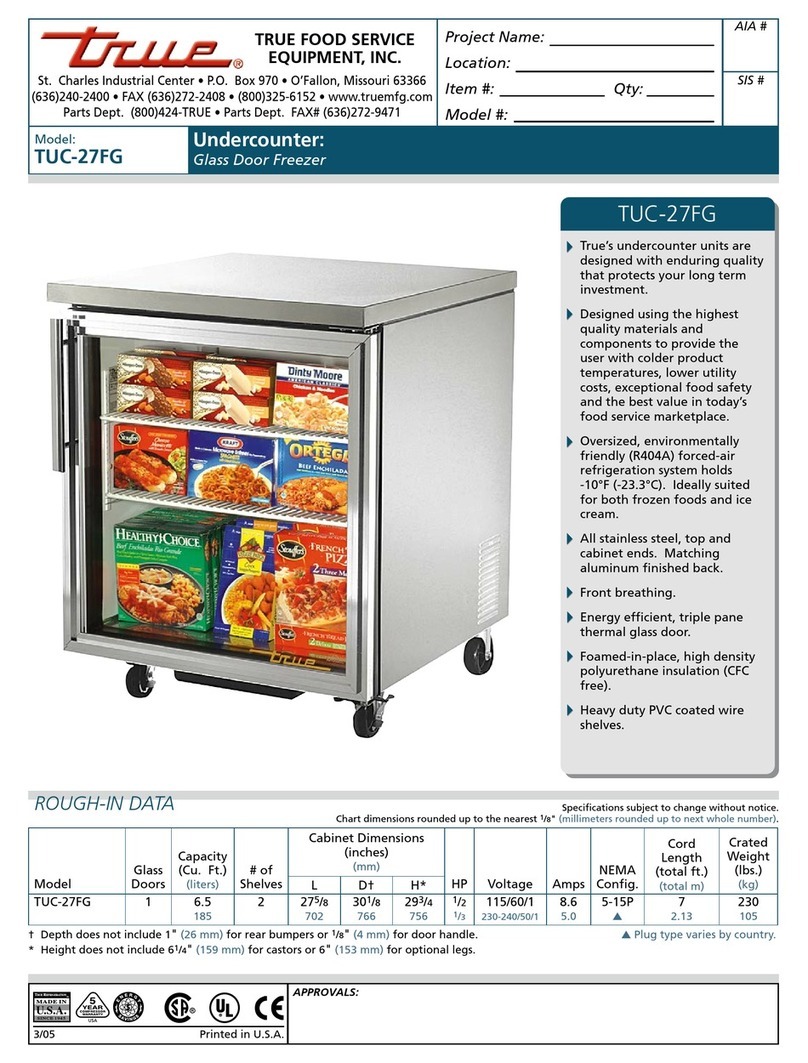
True
True TUC-27FG Specifications
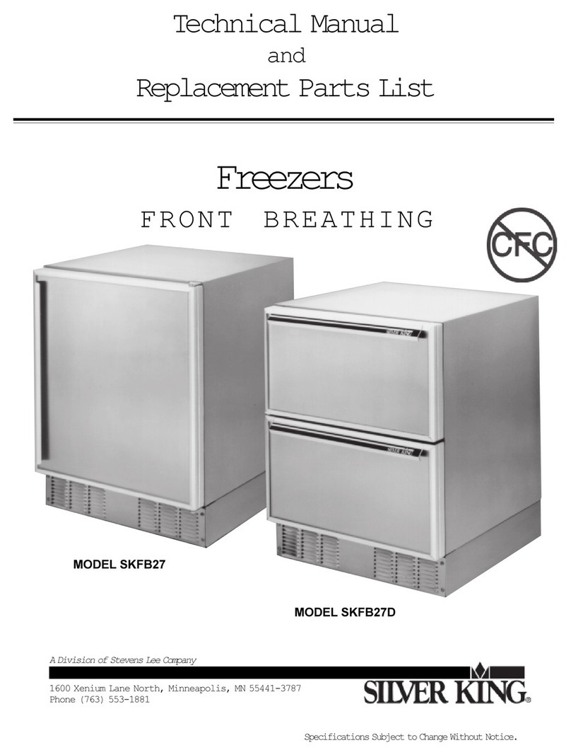
Stevens
Stevens Silver King SKFB27 Technical manual and replacement parts list
Frigidaire
Frigidaire FFC09K0DW Factory parts catalog
Ariston
Ariston RG 2330 operating instructions
CONTINENTAL EDISON
CONTINENTAL EDISON MF-181W user manual
Miele
Miele F 1471 Vi OPERATING AND INSTALLATION Manual


