Forte F2413MV5SS User manual
READ CAREFULLY.
KEEP THESE INSTRUCTIONS.
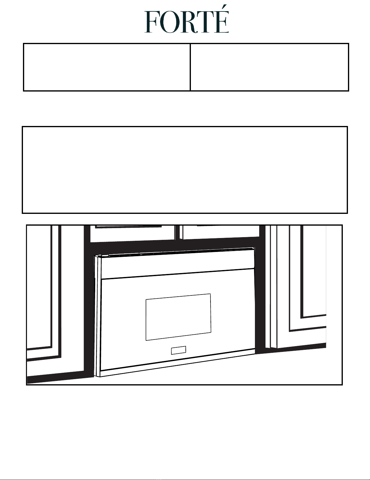
Installation
Instructions 24" Over the Range
Microwave Oven
Read these instructions completely and carefully.
•IMPORTANT – Save these
instructions for local inspector’s use.
•IMPORTANT – Observe all
governing codes and ordinances.
•Note to Installer – Be sure to leave these
instructions with the Consumer.
BEFORE YOU BEGIN •Note to Consumer – Keep these
instructions for future reference.
•Skill level – Installation of this appliance requires
basic mechanical and electrical skills.
•Proper installation is the responsibility of the installer.
•Product failure due to improper installation is not
covered under the Warranty.
F2413MV5SS

Before You Use Your Microwave
CONTENTS
General information
Important Safety Instructions .................................. 3
Electrical Requirements .......................................... 3
Damage – Shipment/Installation.............................. 4
Parts Included.......................................................... 4
Tools You Will Need ................................................ 5
Mounting Space ...................................................... 5
Step-by-step installation guide
6–8
Removing the Mounting Plate ...................... 6
Finding the Wall Studs.................................. 6
Determining Wall Plate Location.................. 7
Aligning the Wall Plate ................................ 8
Outside Top Exhaust
Attach Mounting Plate to Wall............12
Preparation of Top Cabinet................13
Checking for Proper Damper
Adapting Microwave Blower
A
B
C
Installation Instructions
21
20
20
Recirculating ........................................
Mount the Microwave Oven ................19
Preparation of Top Cabinet ................17
Attach Mounting Plate to Wall ............17
Outside Back Exhaust..........................16
Connecting Ductwork..........................15
Adjust the Exhaust Adaptor ................15
Operation............................................14
Outside Back Exhaust............................ 16–19
Adapting Microwave Blower for
Outside top Exhaust .......... 13–14........
Placement of The Mounting Plate ......................
............................ 12–15
Preparing Rear Wall for
Remove Blower Plate ...................... 16...... ..
Charcoal Filter
Installing or Change the
22
Preparation of Top Cabinet ................2
Check Blower Plate ............................
.......................... 25
....................................22
Attach Mounting Plate to Wall............
22
–
Installation Types............................................... 9–22
for Outside Back Exhaust................17 18
–
Mount the Microwave Oven ..........21–
Hood Exhaust.................................................. 10 11
–
Mount the Microwave Oven ..........14 15
–
.......................... 2Template Information...................
1
EN-2
6
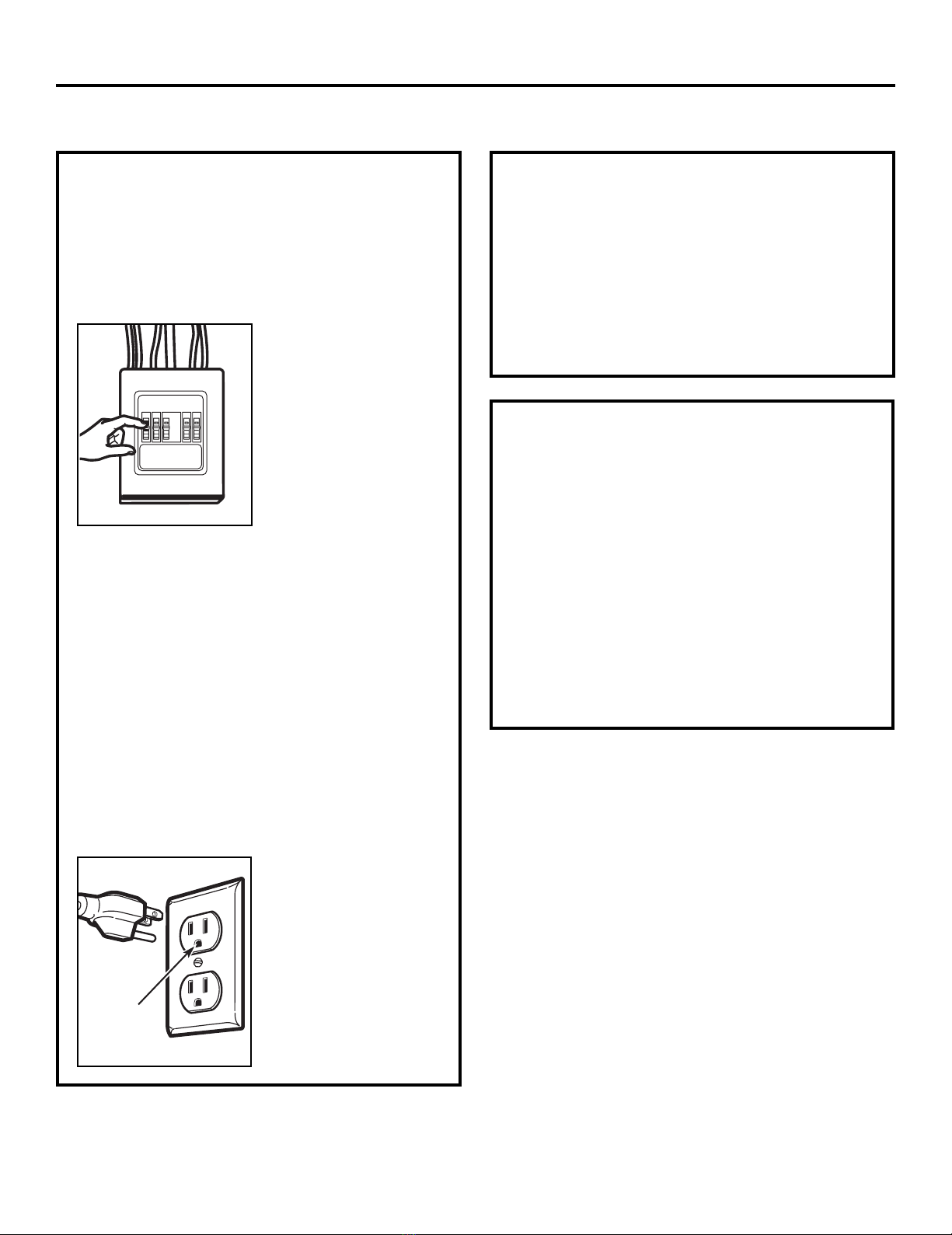
This product requires a three-prong grounded outlet.
The installer must perform a ground continuity check
on the power outlet box before beginning the
installation to ensure that the outlet box is properly
grounded. If not properly grounded, or if the outlet
box does not meet electrical requirements noted
(under ELECTRICAL REQUIREMENTS), a qualified
electrician should be employed to correct any
deficiencies. CAUTION: For personal
safety, remove house fuse
or open circuit breaker
before beginning
installation to avoid severe
or fatal shock injury.
CAUTION: For personal safety, the mounting surface
must be capable of supporting the cabinet load, in
addition to the added weight of this 63–85 pound
(28.5–38.5 kg) product, plus additional oven loads of
up to 50 pounds (22.7 kg) or a total weight of
113–135 pounds (51.3–61.2 kg).
CAUTION: For personal safety, this product cannot
be installed in cabinet arrangements such as an island or
a peninsula. It must be mounted to BOTH a top cabinet
AND a wall.
NOTE: For easier installation and personal safety, it is
recommended that two people install this product.
IMPORTANT – PLEASE READ CAREFULLY. FOR
PERSONAL SAFETY, THIS APPLIANCE MUST BE
PROPERLY GROUNDED TO AVOID SEVERE OR
FATAL SHOCK.
The power cord of this
appliance is equipped with a
three-prong (grounding)
plug which mates with a
standard three-prong
(grounding) wall receptacle
to minimize the possibility
of electric shock hazard
from this appliance.
You should have the wall receptacle and circuit checked
by a qualified electrician to make sure the receptacle is
properly grounded.
Where a standard two-prong wall receptacle is
encountered, it is very important to have it replaced
with a properly grounded three-prong wall receptacle,
installed by a qualified electrician.
DO NOT, UNDER ANY CIRCUMSTANCES, CUT,
DEFORM OR REMOVE ANY OF THE PRONGS
FROM THE POWER CORD. DO NOT USE WITH
AN EXTENSION CORD.
IMPORTANT SAFETY INSTRUCTIONS
Ensure proper
ground exists
before use
Installation Instructions
EN-3
ELECTRICAL
REQUIREMENTS
Product rating is 120 volts AC, 60 Hertz, 15 amps and
1.6 kilowatts. This product must be connected to a
The power supply cord and plug should be brought to a
the prevailing local code for this kilowatt rating.
the requirements of the National Electrical Code or
voltage and frequency. Wire size must conform to
seperate and dedicated supply circuit of the proper
seperate and dedicated 15- to 20- ampere branch
National Electrical Code or the prevailing local code.
by a qualifed electrician and conform to the
The outler box and supply circuit should be installed
be located in the cabinet above the microwave oven.
circuit single grounded outlet. The outlet box should

PART QUANTITY
Wood Screws 2
(1⁄4“ x 2“)
Toggle Bolts (and
wing nuts) (3⁄16“ x 3“)
Self-Aligning Machine 3
Screws (1⁄4“-28 x 31⁄4“)
Nylon Grommet
(for metal cabinets) 1
•If the unit is damaged in shipment, return the
unit to the store in which it was bought for repair
or replacement.
•If the unit is damaged by the customer, repair or
replacement is the responsibility of the customer.
•If the unit is damaged by the installer (if other
than the customer), repair or replacement must
be made by arrangement between customer
and installer.
DAMAGE—SHIPMENT/
INSTALLATION
Installation Instructions
PARTS INCLUDED
You will find the installation hardware contained in
a packet with the unit. Check to make sure you have
all these parts.
NOTE: Some extra parts are included.
HARDWARE PACKET
PART
QUANTITY
Template 1
Template
Installation
1
Instructions
Separately 2
Packed
Filters
PARTS INCLUDED (CONT.)
INSTALLATION
INSTRUCTIONS
ADDITIONAL PARTS
1
adaptor
Grease
Exhaust
Glass
1
Tray
1
Ring
T ru ntable
CabinetTop
Rear Wall
2
1
Use & Care
1
USE & CARE
MANUAL
Manual
EN-4

TOOLS YOU WILL NEED
# 1 Phillips screwdriver Pencil Ruler or tape measure and
straight edge Carpenter square
(optional)
Tin snips (for cutting
damper, if required) Electric drill with 3⁄16“, 1⁄2“and 5⁄8“
drill bits
Hammer (optional)
Stud finder or
Filler blocks or scrap
wood pieces, if needed
for top cabinet spacing
(used on recessed bottom
cabinet installations only)
Gloves
Saw (saber, hole or keyhole)
Level Duct and masking tape
Installation Instructions
Scissors
(to cut template, if necessary)
Safety goggles
MOUNTING SPACE NOTES:
•The space between the cabinets must be
(61.0cm)wide and free of obstructions.
•If you are going to vent your microwave oven
to the outside, see Hood Exhaust Section for
exhaust duct preparation.
•When installing the microwave oven beneath
smooth, flat cabinets, be careful to follow the
instructions on the top cabinet template for
power cord clearance.
Bottom Edge of
Cabinet Needs to
be
or More from the
Cooking Surface
Backsplash
66w(167.6 cm)
or More from
the Floor to the
Topofthe
Microwave
2“ (5.1 cm)
30“
(76.2 cm)
min.
161⁄2“(41.9 cm)
13 Maximum (33 cm)
“
As a guide to installation, see page 24 for Mounting
Template Information.
•
•
CabinetCabinet
If the cabinet depth including the cabinet doors
is more th n 13'""' th n the unit must be spaced
out from wall using adequate materials supporting
150 Ibs to allow proper top vent air exhaust/intake.
a e
EN-5
24“(61.0cm)
24“
" (76.2 cm)
"
30

PLACEMENT OF THE MOUNTING PLATE
1
Installation Instructions
Find the studs, using one of the following
methods:
A. Stud finder – a magnetic device which
locates nails.
B. Use a hammer to tap lightly across the
mounting surface to find a solid sound.
This will indicate a stud location.
After locating the stud(s), find the center by
probing the wall with a small nail to find the edges
of the stud. Then place a mark halfway between
the edges. The center of any adjacent studs should
be 16w(40.6 cm) or 24w(61 cm) from this mark.
Draw a line down the center of the studs.
THE MICROWAVE MUST BE CONNECTED TO
AT LEAST ONE WALL STUD.
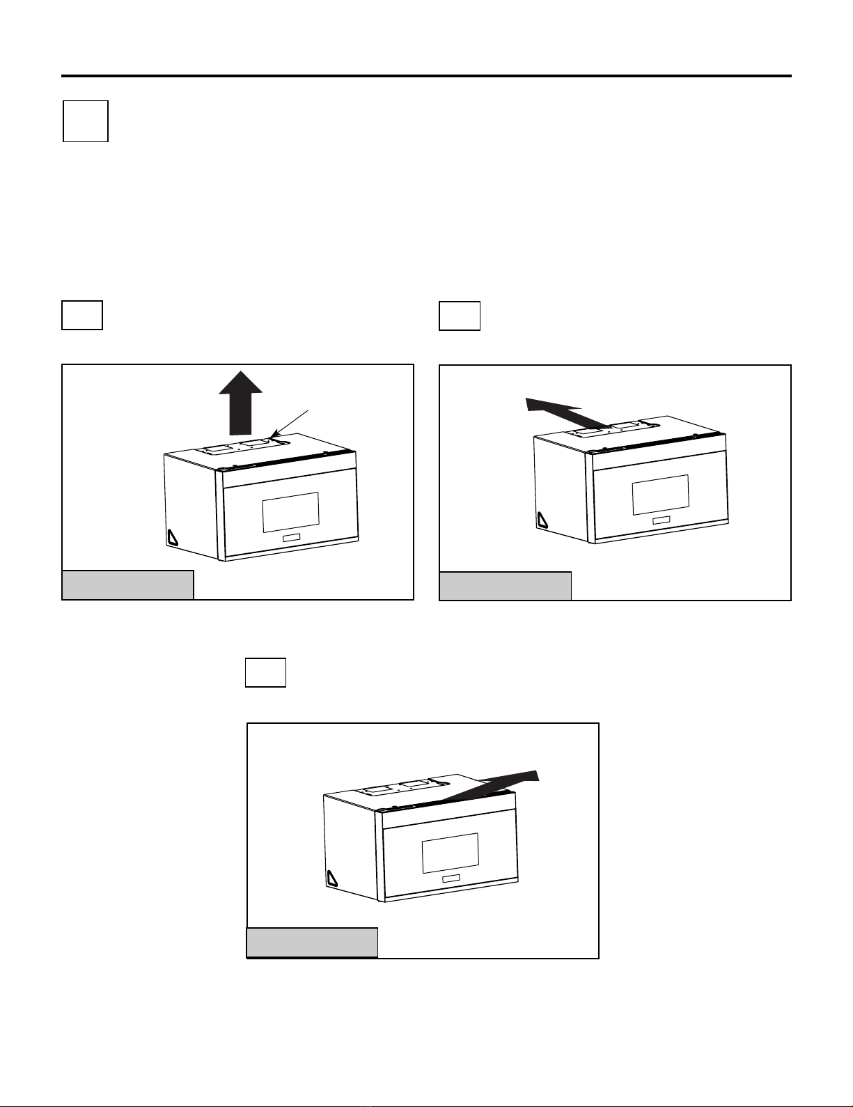
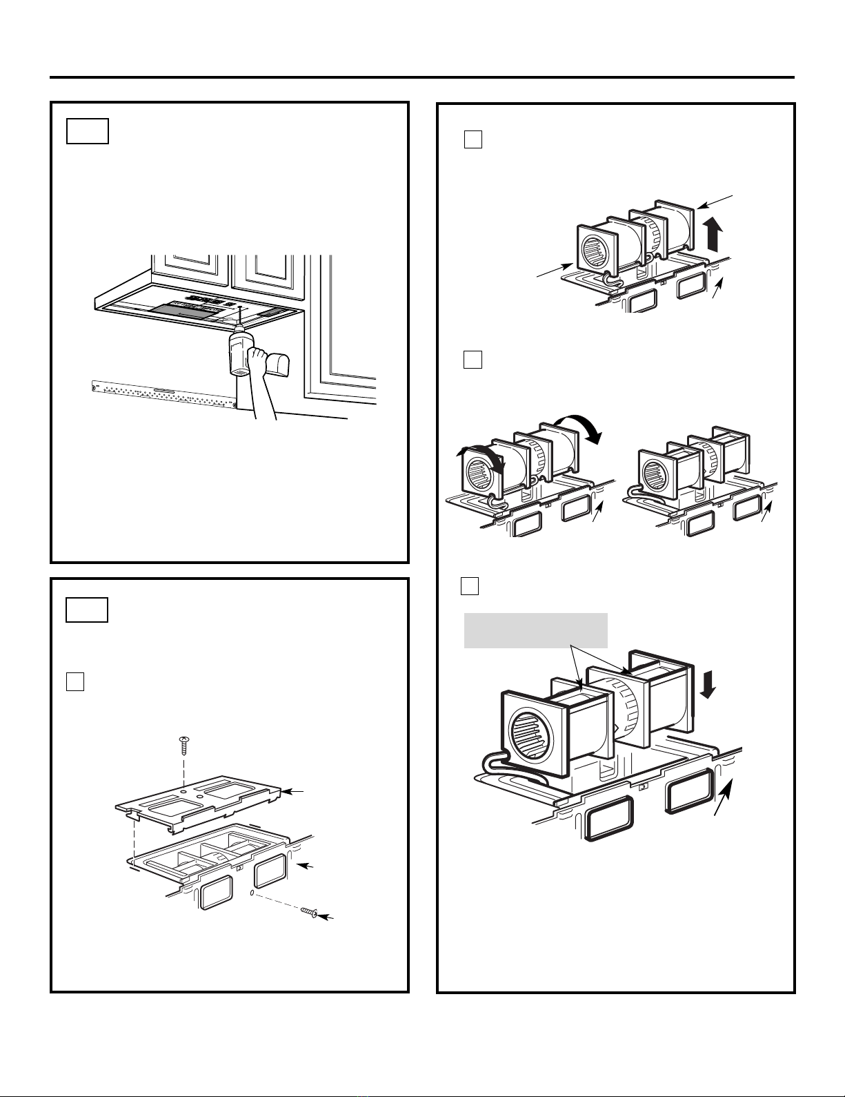
1
Fold back all 4 carton flaps fully against carton
sides. Then carefully roll the oven and carton over
onto the top side. The oven should be resting in
the Styrofoam.
REMOVING THE MICROWAVE
OVEN FROM THE CARTON/
REMOVING THE MOUNTING
PLATE
FINDING THE WALL STUDS
B.
A.
2
Wall
Studs
Center
3
Carton
Pull the carton up and off the oven.
2
Styrofoam
3
1
Screws Screws
Mounting Plate
5
4Cut the middle of the outer protective plastic bag to
remove the ounting late
mp
Filters and Turntable
Ring below glass tray
Exhaust Adapter
Small Hardware Bag
Glass Tray
Shelf ( For some
Remove the installation instructions,use and care,
exhaust adapter, turntable ring, shelf, filters, glass
Do notremove
the Styrofoam protecting the front of the oven.
Remove the screws from each end of the mounting
plate. This plate will be used as the rear wall template
bag.
and for mounting. Reinstall the screws into the holes
where they were removed.
tray and the small hardware
EN-6
models)

DETERMINING WALL PLATE LOCATION UNDER YOUR CABINET
C.
Installation Instructions
Plate position flat bottom
cabinet
Draw a line on the
back wall equal to the
depth of the front
overhang.
to Cooktop
C
3/8"TOEDGE
NOTE:ITISVERY IMPORTANT TO
READANDFOLLOWTHEDIRECTIONS
INTHEINSTALLATIONINSTRUCTIONS
BEFOREPROCEEDINGWITHTHIS
REARWALLTEMPLATE.
ThisRearWallTemplateservesto positionthe bottom
mountingplateandtolocatethehorizontal exhaust
outlet.
1.Usealeveltocheckthatthe template is positioned
accurately.
2.Locateandmarkatleastonestudon theleft or
rightsideofthecenterline.
Itisimportanttouseat least one wood
screwmountedfirmlyinastudto supportthe weight
ofthemicrowave.Marktwo additional, evenly spaced
locationsforthesuppliedtoggle bolts.
3.Drillholesinthemarkedlocations.Wherethere is
astud,drilla3/16"hole for wood screws.For holes
thatdonotlineup witha stud,drill 5/8"holesfor
togglebolts.
DONOTINSTALLTHEMOUNTING PLATE
ATTHISTIME.
4.Removethetemplatefromtherear wall.
5.ReviewtheInstallationInstruction book for your
installationsituation.
Locateandmarkholes to align withholesinthe
mountingplate.
IMPORTANT:
LOCATEATLEASTONESTUDON EITHER SIDE OF
THECENTERLINE.
MARKTHELOCATIONFOR2ADDITIONAL, EVENLY
SPACEDTOGGLEBOLTS IN THE MOUNTING PLATE
AREA.
Locateandmarkholes to align with holes in the
mountingplate.
IMPORTANT:
LOCATEATLEAST ONE STUDON EITHER SIDE OF
THECENTERLINE.
MARKTHELOCATION FOR 2 ADDITIONAL,EVENLY
SPACEDTOGGLEBOLTSIN THE MOUNTING PLATE
AREA.
Trimtherearwall template along the dottedline.
Trimtherear wall template alongthedottedline.
12"
4"
Darlevueltaalahojapara consultarla
versiónenEspañol.
C
L
3/8"TOEDGE
NOTE:ITIS VERY IMPORTANT TO
READAND FOLLOW THE DIRECTIONS
INTHEINSTALLATIONINSTRUCTIONS
BEFOREPROCEEDINGWITH THIS
REARWALL TEMPLATE.
ThisRearWall Template serves to positionthe bottom
mountingplateand to locatethe horizontal exhaust
outlet.
1.Usea level to check thatthe template is positioned
accurately.
2.Locateand markat leastonestudonthe left or
rightsideofthecenterline.
Itis important touse at least one wood
screwmountedfirmly in a studto support the weight
ofthemicrowave. Mark two additional, evenly spaced
locationsforthesupplied toggle bolts.
3.Drill holesin the markedlocations. Where there is
astud,drill a 3/16" hole forwood screws.Forholes
thatdonot line upwith a stud, drill 5/8" holes for
togglebolts.
DONOTINSTALLTHE MOUNTINGPLATE
ATTHIS TIME.
4.Remove thetemplate from the rear wall.
5.Reviewthe Installation Instruction book for your
installationsituation.
Locateandmark holes to align with holes in the
mountingplate.
IMPORTANT:
LOCATEAT LEAST ONE STUDON EITHER SIDE OF
THECENTERLINE.
MARKTHE LOCATIONFOR2 ADDITIONAL,EVENLY
SPACEDTOGGLE BOLTS IN THE MOUNTINGPLATE
AREA.
Locateandmark holes to align withholes in the
mountingplate.
IMPORTANT:
LOCATEAT LEAST ONE STUD ON EITHER SIDEOF
THECENTERLINE.
MARKTHE LOCATION FOR 2 ADDITIONAL, EVENLY
SPACEDTOGGLE BOLTS INTHE MOUNTING PLATE
AREA.
Trimtherear wall template along the dotted line.
Trimtherear walltemplate along the dotted line.
12"
4"
Darlevueltaa la hoja para consultarla
versiónenEspañol.
²
Atleast
″
C
3/8"TOEDGE
NOTE:ITIS VERY IMPORTANT TO
READAND FOLLOW THE DIRECTIONS
INTHE INSTALLATION INSTRUCTIONS
BEFOREPROCEEDING WITH THIS
REARWALL TEMPLATE.
ThisRear Wall Templateserves to positionthe bottom
mountingplateand to locate thehorizontal exhaust
outlet.
1.Use a level to check that the template is positioned
accurately.
2.Locate and mark at least one studon theleft or
right sideof thecenterline.
Itis important to use at least one wood
screwmountedfirmlyin a studto support theweight
ofthemicrowave. Mark two additional, evenly spaced
locationsfor thesupplied toggle bolts.
3.Drillholes in themarked locations. Where there is
astud, drill a 3/16"hole for woodscrews. Forholes
that do not lineupwith astud, drill 5/8" holes for
toggle bolts.
DONOT INSTALLTHE MOUNTING PLATE
ATTHIS TIME.
4.Removethe template fromtherear wall.
5.Review the InstallationInstruction book foryour
installation situation.
Locateand mark holes toalign with holes in the
mountingplate.
IMPORTANT:
LOCATEAT LEAST ONE STUD ON EITHER SIDE OF
THECENTERLINE.
MARKTHE LOCATION FOR 2 ADDITIONAL, EVENLY
SPACEDTOGGLE BOLTS IN THE MOUNTING PLATE
AREA.
Locateand mark holes to align with holes in the
mountingplate.
IMPORTANT:
LOCATEAT LEAST ONE STUDON EITHER SIDE OF
THECENTERLINE.
MARKTHE LOCATION FOR 2 ADDITIONAL, EVENLY
SPACEDTOGGLE BOLTS IN THE MOUNTING PLATE
AREA.
Trimthe rear walltemplate alongthe dotted line.
Trimthe rear walltemplate along the dottedline.
12"
4"
Darlevueltaa la hoja para consultar la
versiónenEspañol.
Your cabinets may have decorative trim that
interferes with the microwave installation. Remove
the decorative trim to install the microwave properly
and to make it level.
THE MICROWAVE MUST BE LEVEL.
Use a level to make sure the cabinet bottom is level.
If the cabinets have a front overhang only, with no
back or side frame, install the mounting plate down
the same distance as the front overhang depth. This
will keep the microwave level.
Measure the inside depth of the front overhang.
Draw a horizontal line on the back wall an equal
distance below the cabinet bottom as the inside
depth of the front overhang.
For this type of installation with front overhang
only, align the mounting tabs with this horizontal
line, not touching the cabinet bottom as described
in Step D.
Draw a vertical line on
the wall at the center of
the 24 ″wide space.
Tape the Rear Wall
Template onto the wall
matchingthecenterline
and touching the
bottom of the cabinet.
to Cooktop
Draw a vertical line on the wall at the center of the
space.
Tape the Rear Wall Template onto the wall
matching the centerline and touching the bottom
C
3/8"TOEDGE
NOTE:ITIS VERY IMPORTANT TO
READAND FOLLOW THE DIRECTIONS
INTHE INSTALLATION INSTRUCTIONS
BEFOREPROCEEDING WITHTHIS
REARWALL TEMPLATE.
ThisRearWallTemplate serves to position the bottom
mountingplateand tolocate thehorizontal exhaust
outlet.
1.Usea levelto check that thetemplate ispositioned
accurately.
2.Locate and mark at least onestudon the left or
rightsideof thecenterline.
Itis important touse at least one wood
screwmounted firmly ina studto support the weight
ofthe microwave. Mark twoadditional, evenly spaced
locationsfor the suppliedtoggle bolts.
3.Drill holes inthemarkedlocations. Wherethere is
astud,drill a 3/16" hole for wood screws. For holes
thatdonotlineup withastud, drill 5/8" holes for
togglebolts.
DONOT INSTALL THE MOUNTING PLATE
ATTHIS TIME.
4.Remove thetemplate from the rear wall.
5.Reviewthe InstallationInstruction book foryour
installationsituation.
Locateand mark holes to align with holes in the
mountingplate.
IMPORTANT:
LOCATEATLEAST ONE STUD ON EITHER SIDE OF
THECENTERLINE.
MARKTHELOCATION FOR 2 ADDITIONAL, EVENLY
SPACEDTOGGLE BOLTSIN THEMOUNTING PLATE
AREA.
Locateand mark holes to align with holes in the
mountingplate.
IMPORTANT:
LOCATEATLEAST ONESTUD ON EITHER SIDE OF
THECENTERLINE.
MARKTHE LOCATION FOR 2ADDITIONAL, EVENLY
SPACEDTOGGLE BOLTS IN THE MOUNTING PLATE
AREA.
Trimthe rear wall template along the dottedline.
Trimtherear wall template along the dotted line.
12"
4"
Darlevuelta a la hoja para consultarla
versiónenEspañol.
cabinet bottom
with front overhang
Plate position framed
recessed
Plate position
bottom
1
3
2
300″0
cabinet frame.
300″0
2″
16-1/2
-beneath
-beneath
-beneath recessed
cabinet
EN-7
24"
24"
24"
24
24"
24"
30
30

Installation Instructions
ALIGNING THE WALL PLATE
D.
CAUTION: Wear gloves
to avoid cutting fingers on
sharp edges.
Area E Hole A
Hole B
Centerline
notches Draw a Vertical Line
on Wall from Center
of Top Cabinet
Draw a horizontal line on wall at the
bottom of “Rear Wall Template”.
Horizontal Line
Horizontal Line
C
L
3/8" TO EDGE
%#76+10Ä+(':*#756#ਸ਼+5215+6+10'&1765+&'
4'%1//'0&'&&+/'05+10)4'#5'Ä.#&'0#+49+..
&+5%*#4)'+061*175'5647%674'
/+0+/7/9+&6*4'37+4'&
4'#49#..6'/2.#6'
NOTE: IT IS VERY IMPORTANT TO
READ AND FOLLOW THE DIRECTIONS
IN THE INSTALLATION INSTRUCTIONS
BEFORE PROCEEDING WITH THIS
REAR WALL TEMPLATE.
This Rear Wall Template serves to position the bottom
mounting plate and to locate the horizontal exhaust
outlet.
1. Use a level to check that the template is positioned
accurately.
2. Locate and mark at least one stud on the left or
right side of the centerline.
016'
It is important to use at least one wood
screw mounted firmly in a stud to support the weight
of the microwave. Mark two additional, evenly spaced
locations for the supplied toggle bolts.
3. Drill holes in the marked locations. Where there is
a stud, drill a 3/16" hole for wood screws. For holes
that do not line up with a stud, drill 5/8" holes for
toggle bolts.
016'
DO NOT INSTALL THE MOUNTING PLATE
AT THIS TIME.
4. Remove the template from the rear wall.
5. Review the Installation Instruction book for your
installation situation.
Locate and mark holes to align with holes in the
mounting plate.
IMPORTANT:
LOCATE AT LEAST ONE STUD ON EITHER SIDE OF
THE CENTERLINE.
MARK THE LOCATION FOR 2 ADDITIONAL, EVENLY
SPACED TOGGLE BOLTS IN THE MOUNTING PLATE
AREA.
Locate and mark holes to align with holes in the
mounting plate.
IMPORTANT:
LOCATE AT LEAST ONE STUD ON EITHER SIDE OF
THE CENTERLINE.
MARK THE LOCATION FOR 2 ADDITIONAL, EVENLY
SPACED TOGGLE BOLTS IN THE MOUNTING PLATE
AREA.
Trim the rear wall template along the dotted line.
%
#
$%
&
(%76176(14*14+<106#.
1765+&'':*#756
%76*1.'6*417)*4'#49#..(14':*#756#ਸ਼
12"
4"
Darle vuelta a la hoja para consultar la
versión en Español.
Draw a vertical line on the wall at the center of the
NOTE: DO NOT MOUNT THE PLATE AT THIS
TIME.
NOTE: Holes A and B are inside area E. If neither of
important to have at least one wood screw mounted
firmly in a stud to support the weight of the
microwave. Set the mounting plate aside.
1
2Draw a horizontal line on the wall at the bottom of
“Rear Wall Template”.
Holes A and B are not in a stud, find a stud somewhere
in area E and draw a circle to line up with the stud. It is
3Find a wall stud in area "E" of mounting plate
Refer to section 1B. Finding the wall studs.
For attaching the mounting plate into stud drill
a 3/16" hole into wood stud. Drill a 5/8" hole for
toggle bolt in 1 other location (Hole A or Hole B)
4
EN-8
24"
24" wide space.
A
INSTALLATION TYPES
This microwave oven is designed for adaptation to
the following three types of ventilation:
A.Outside Top Exhaust (Vertical Duct)
B.Outside Back Exhaust (Horizontal Duct)
C.Recirculating (Non-Vented Ductless)
proceed to that section.
OUTSIDE TOP EXHAUST
(VERTICAL DUCT) OUTSIDE BACK EXHAUST
(HORIZONTAL DUCT)
RECIRCULATING
(NON-VENTED DUCTLESS)
See page 12
recirculating exhaust.
disposable charcoal filter
installed to help remove
smoke and odors.
Adaptor in Place for
Outside Top Exhaust
2
B
C
Adaptor Must Be
Moved to the Back for
Outside Back Exhaust
NOTE: This microwave is shipped assembled for
Recirculating. Select the type of ventilation required
(Choose A, B or C)
for your installation and
See page 16
See page 20
Models are shipped for
Some models have a
Installation Instructions
NOTE: Read the next two pages only if you plan to vent your exhaust to the
outside. If you plan to recirculate the air back into the room, proceed to page 20.
EN-9

EQUIVALENT NUMBER EQUIVALENT
DUCT PIECES LENGTH x USED = LENGTH
Rectangular-to-Round 5 Ft. (1.5 m) x ( ) = Ft. or m
Transition Adaptor*
Wall Cap 40 Ft. (12.2 m) x ( ) = Ft. or m
90° Elbow 10 Ft. (3 m) x ( ) = Ft. or m
45° Elbow 5 Ft. (1.5 m) x ( ) = Ft. or m
90° Elbow 25 Ft. (7.6 m) x ( ) = Ft. or m
45° Elbow 5 Ft. (1.5 m) x ( ) = Ft. or m
Roof Cap 24 Ft. (7.3 m) x ( ) = Ft. or m
Straight Duct 6“ (15.2 cm) 1 Ft. (0.3 m) x ( ) = Ft. or m
Round or 31⁄4“ x 10“
(8.2 x 25.4 cm Rectangular)
Total Ductwork = Ft. or m
Equivalent lengths of duct pieces are based on actual tests
and reflect requirements for good venting performance with
any vent hood.
* IMPORTANT: If a rectangular-to-round transition
adaptor is used, the bottom corners of the damper
will have to be cut to fit, using the tin snips, in order
to allow free movement of the damper
.
NOTE: If you need to install ducts, note that the total
duct length of 31⁄4”x 10”(8.2 x 25.4 cm) rectangular or
”(15.2 cm) diameter round duct
Outside ventilation requires an EXTERNAL EXHAUST
NOTE: It is important that venting be installed using
the most direct route and with as few elbows as possible.
This ensures clear venting of exhaust and helps prevent
blockages. Also, make sure dampers swing freely and
nothing is blocking the ducts.
Exhaust connection:
The exhaust adaptor has been designed to mate with
a standard 31⁄4”x 10”(8.2 x 25.4 cm) rectangular duct.
If a round duct is required, a rectangular-to-round
Maximum duct length:
For satisfactory air movement, the total duct length of
31⁄4”x 10”(8.2 x 25.4 cm) rectangular or
6 ”(15.2 cm) diameter round duct should not
exceed 120 equivalentfeet (36.5 m).
Elbows, transitions, wall and roof caps,
etc., present additional resistance to airflow and are
equivalent to a section of straight duct which is longer
than their actual physical size. When calculating the total
duct length, add the equivalent lengths of all transitions
and adaptors plus the length of all straight duct sections.
The chart below shows you how to calculate total
equivalent ductwork length using the approximate feet
of equivalent length of some typical ducts.
Installation Instructions
INSTALLATION INSTRUCTIONS FOR EXTERNAL EXHAUST DUCTING
DUCT.Read the following carefully.
(12.5”
should not exceed 120 equivalent feet (36.5 m).
diameter/ 6 (12.5”
diameter/ 7 cm)
7 cm)
transition adaptor must be used.
diameter duct is acceptable to use. "
A 5"""'''''" (12.7cm)/ 6" (15.2cm)
"
EN-10

EQUIVALENT NUMBER EQUIVALENT
DUCT PIECES LENGTH x USED = LENGTH
Roof Cap 24 Ft. (7.3 m) x (1) = 24 Ft. (7.3 m)
12 Ft. (3.6 m) Straight Duct 12 Ft. (3.6 m) x (1) = 12 Ft. (3.6 m)
(6”/15.2 cm Round)
Rectangular-to-Round 5 Ft. (1.5 m) x (1) = 5 Ft. (1.5 m)
Transition Adaptor*
Equivalent lengths of duct pieces are based on actual tests and
reflect requirements for good venting performance with any vent hood. Total Length = 41 Ft. (12.5 m)
The following chart describes an example of one possible
ductwork installation.
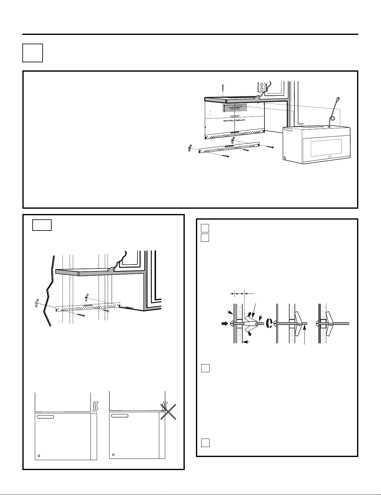
OUTSIDE TOP EXHAUST (EXAMPLE ONLY)
NOTE: For back exhaust, care should be taken to align exhaust with space between studs, or wall should be prepared
at the time it is constructed by leaving enough space between the wall studs to accommodate exhaust.
* IMPORTANT: If a rectangular-to-round transition adaptor is used, the bottom corners of the damper
will have to be cut to fit, using the tin snips, in order to allow free movement of the damper.
The following chart describes an example of one possible
ductwork installation.
Installation Instructions
OUTSIDE BACK EXHAUST (EXAMPLE ONLY)
EQUIVALENT NUMBER EQUIVALENT
DUCT PIECES LENGTH* x USED = LENGTH
Wall Cap 40 Ft. (12.2 m) x (1) = 40 Ft. (12.2 m)
3 Ft. Straight Duct 3 Ft. (0.9 m) x (1) = 3 Ft. (0.9 m)
(31⁄4” x 10”/8.2 x 25.4 cm
Rectangular)
90° Elbow 10 Ft. (3 m) x (2) = 20 Ft. (3 m)
Equivalent lengths of duct pieces are based on actual tests and
reflect requirements for good venting performance with any vent hood. Total Length = 63 Ft. (19.2 m)
EXTERNAL EXHAUST DUCTING
EN-11
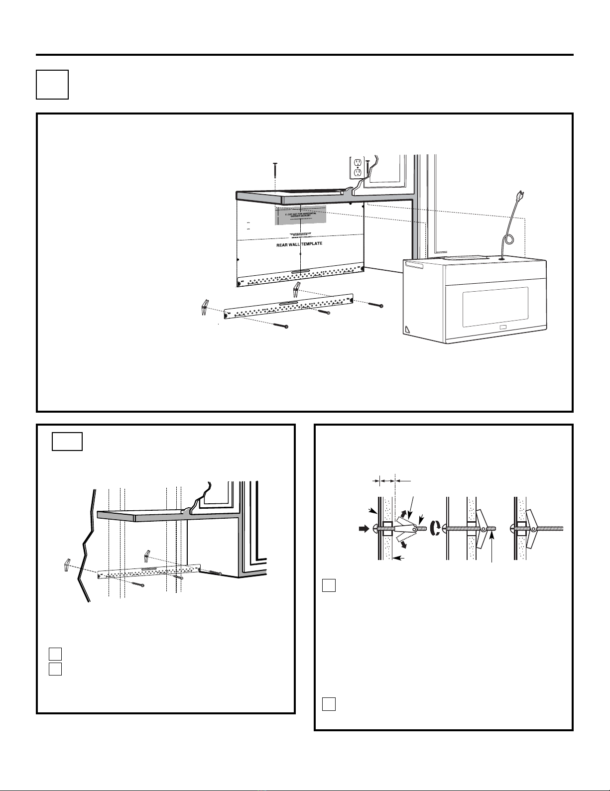
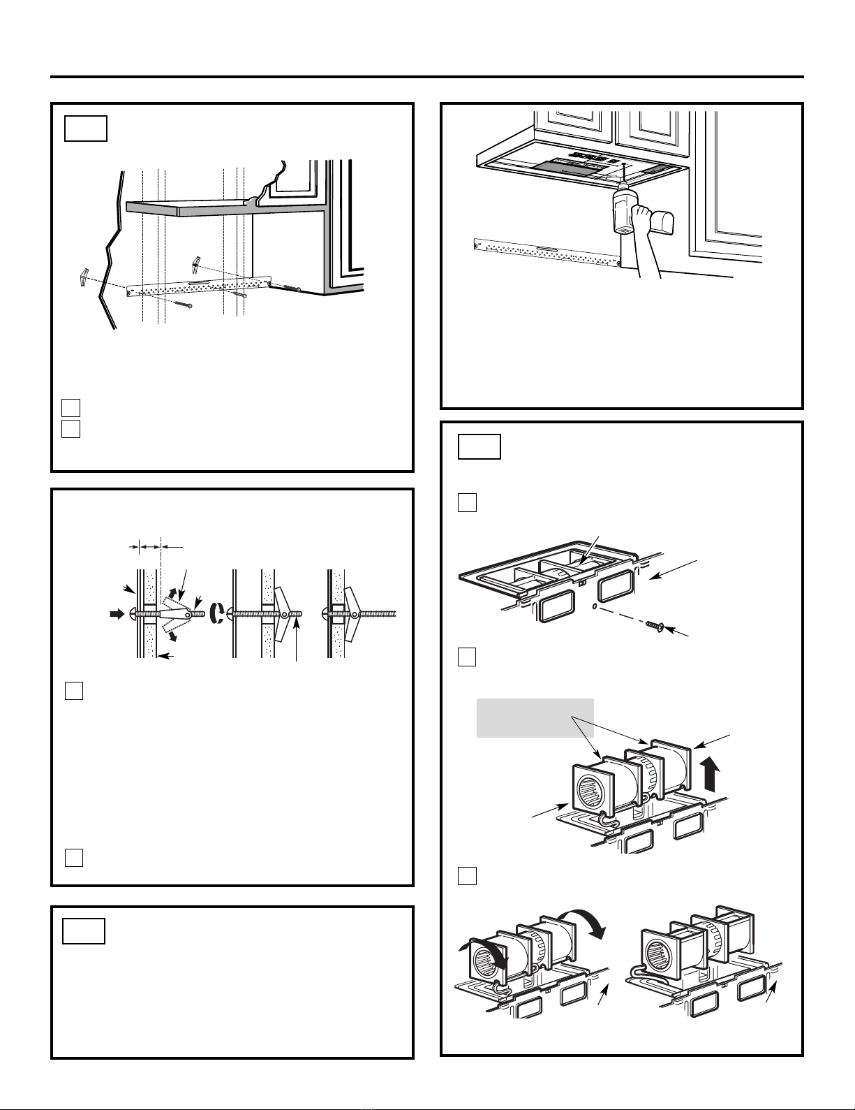
Place the mounting plate against the wall and
insert the toggle wings into the holes in the wall
to mount the plate.
NOTE: Before tightening toggle bolts and wood
screw, make sure the bottom of the mounting plate
touch the bottom of the cabinet when pushed
flush against the wall and that the plate is properly
centered under the cabinet.
CAUTION: Be careful to avoid pinching fingers
between the back of the mounting plate and the wall.
Tighten all bolts. Pull the plate away from the wall
to help tighten the bolts.
3
4
ATTACH THE MOUNTING
PLATE TO THE WALL
A1.
Attach the plate to the wall using toggle bolts.
At least one wood screw must be used to attach
the plate to a wall stud.
Remove the toggle wings from the bolts.
Insert the bolts into the mounting plate
through the holes designated to go into drywall
and reattach the toggle wings to 3⁄4″(19 mm) onto
each bolt.
1
INSTALLATION OVERVIEW
A1. Attach Mounting Plate to Wall
A2. Prepare Top Cabinet
Mount Microwave Oven
A5. Adjust Exhaust Adaptor
A6.
Wall
Mounting
Plate
Spacing for Toggles
More Than Wall
Thickness
Bolt End
Toggle
Bolt
Toggle Wings
To use toggle bolts:
Installation Instructions
2
OUTSIDE TOP EXHAUST (Vertical Duct)
A
IMPORTANT NOTES:
•Make sure the screws for the
blower motor and blower plate
are securely tightened when
they are reinstalled. This will
help to prevent excessive
vibration.
•Make sure the motor wiring has
been properly routed and secured,
and that the wires are not pinched.
A7.Connect Ductwork
A3.
A4. Check Damper Operation
Adapting Microwave Blower for
Outside Top Exhaust
EN-12
3/8"TOEDGE
NOTE:IT IS VERY IMPORTANT TO
READAND FOLLOWTHE DIRECTIONS
INTHE INSTALLATION INSTRUCTIONS
BEFOREPROCEEDING WITH THIS
REARWALL TEMPLATE.
ThisRearWall Template serves to position thebottom
mountingplate and to locate the horizontal exhaust
outlet.
1.Use a level to checkthat the template is positioned
accurately.
2.Locate and markat least one stud on theleft or
right side of the centerline.
Itis important to use at leastone wood
screwmountedfirmly in a stud to support the weight
ofthe microwave. Mark twoadditional, evenly spaced
locationsforthe supplied toggle bolts.
3.Drill holes in the marked locations. Where there is
a stud, drilla 3/16" hole for wood screws. For holes
that do not line up with a stud, drill 5/8" holesfor
toggle bolts.
DONOT INSTALLTHEMOUNTING PLATE
ATTHIS TIME.
4.Remove the template fromthe rearwall.
5.Reviewthe Installation Instruction book for your
installation situation.
Locateand mark holes to align with holes in the
mountingplate.
IMPORTANT:
LOCATEAT LEAST ONESTUD ON EITHER SIDE OF
THECENTERLINE.
MARKTHE LOCATION FOR 2 ADDITIONAL, EVENLY
SPACEDTOGGLE BOLTS IN THE MOUNTING PLATE
AREA.
Locateand markholes to align with holes in the
mountingplate.
IMPORTANT:
LOCATEAT LEAST ONE STUD ON EITHER SIDE OF
THECENTERLINE.
MARKTHE LOCATIONFOR 2 ADDITIONAL, EVENLY
SPACEDTOGGLE BOLTS IN THE MOUNTING PLATE
AREA.
Trimthe rear wall template along the dotted line.
Trimthe rear wall template along the dotted line.
12"
4"
Darlevueltaala hojapara consultar la
versiónen Español.
24"
USE TOP CABINET TEMPLATE
FOR PREPARATION OF TOP
CABINET
You need to drill holes for the top support screws, a
hole large enough for the power cord to fit through,
and a cutout large enough for the exhaust adaptor.
A2.
•Read the instructions on the TOP CABINET
TEMPLATE.
•Tape it underneath the top cabinet.
•Drill the holes, following the instructions on the
TOP CABINET TEMPLATE.
CAUTION: Wear safety goggles when drilling holes
in the cabinet bottom.
Installation Instructions
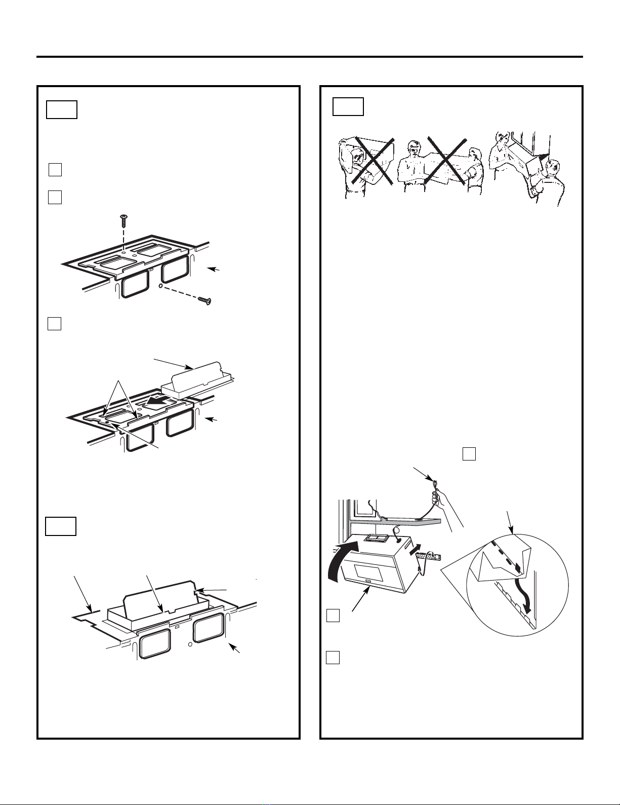
A3.
Remove the screw that holds the blower plate
to the microwave. Remove and save the screw
holding the blower motor to the microwave.
Blower Plate
Blower Motor
Screw
Back of
Microwave
2
End B
End A
Carefully pull out the blower unit. The wires
will extend far enough to allow you to adjust
the blower unit.
1
ADAPTING MICROWAVE
BLOWER FOR OUTSIDE
TOP EXHAUST
Roll the blower unit 90° so that fan blade
microwave.
3
Back of
Microwave
Before Rotation After Rotation
Back of
Microwave
Back of
Microwave
openings are facing out the top of the
Back of
Microwave
AFTER: Fan Blade
Place the blower unit back into the opening.
Openings Facing Top
CAUTION: Do not pull or stretch the blower
unit wiring. Make sure the wires are not
pinched, and that they are properly secured.
4
with the top of the unit facing up.
Place the microwave in its upright position,
EN-13
3
MOUNT THE MICROWAVE
OVEN
FOR EASIER INSTALLATION AND PERSONAL
SAFETY, WE RECOMMEND THAT TWO PEOPLE
INSTALL THIS MICROWAVE OVEN.
NOTE: If your cabinet is metal, use the nylon
grommet around the power cord hole to prevent
cutting of the cord.
NOTE: We recommend using filler blocks if the
cabinet front hangs below the cabinet bottom shelf.
IMPORTANT: If filler blocks are
not used, case damage may occur from
overtightening screws.
Insert a self-aligning screw through top center
cabinet hole. Temporarily secure the oven by
turning the screw at least two full turns after the
threads have engaged. (It will be completely
tightened later.) Be sure to keep power cord
tight. Be careful not to pinch the cord, especially
when mounting flush to bottom of cabinet.
2Rotate front of oven
up against cabinet
bottom.
NOTE: When mounting the
microwave oven, thread
power cord through hole in
bottom of top cabinet. Keep
it tight throughout Steps
1–3. Do not pinch cord or
lift oven by pulling cord. Lift microwave, tilt it
forward, and hook
slots at back bottom
edge onto four lower
tabs of mounting
plate.
1
CHECK FOR PROPER
DAMPER OPERATION
Exhaust Adaptor
Blower Plate
Damper
Back of
Microwave
•Make sure tape securing damper is removed and
damper pivots easily before mounting microwave.
•You will need to make adjustments to assure proper
alignment with your house exhaust duct after the
microwave is installed.
A3.
ADAPTING MICROWAVE
BLOWER FOR OUTSIDE
TOP EXHAUST
Secure blower unit to microwave with the screw
5removed in Step 1. Make sure the screw is tight.
Replace blower plate with the screw removed in
Step 1. Make sure the screw is tight.
Back of
Microwave
6
7
Back of
Microwave
Guide
Adaptor
Locking Tab
damper swings freely.
Attach the exhaust adaptor to the top of the
blower plate by sliding it into the guides of the
blower plate.
Push in securely until it is in the locking tabs.
Take care to assure that the damper hinge is
installed so that the
A4.
A5.
Installation Instructions
EN-14
IMPORTANT: Do not grip or use the handle
or heat shield during installation. Do not
remove the cardboard spacers between the
heat shield and door.
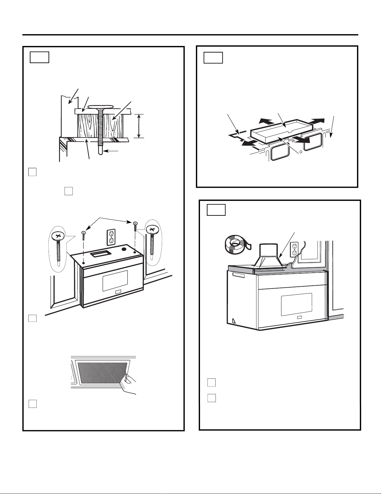
4Attach the microwave oven to the top cabinet.
7
Cabinet Front
Cabinet Bottom Shelf
Tighten the outer two screws to the top of the
microwave oven. (While tightening screws, hold
the microwave oven in place against the wall and
the top cabinet.)
Filler Block
Microwave Oven Top
Equivalent
to Depth
of Cabinet
Recess
Insert 2 self-aligning screws
through outer top cabinet
holes. Turn two full turns on
each screw.
Install grease filters. See the Use &&&&and Care
packed with the microwave.
Installation Instructions
ADJUST THE EXHAUST
ADAPTOR
Open the top cabinet and adjust the exhaust adaptor
to connect to the house duct.
Back of
Microwave
For Front-to-Back or
Side-to-Side Adjustment,
Slide the Exhaust Adaptor
as Needed
Blower Plate Damper
Self-Aligning Screw
5
MOUNT THE MICROWAVE
OVEN (cont.)
A6.
A5.
CONNECTING DUCTWORK
1
2
Extend the house duct down to connect to
the exhaust adaptor.
A7.
furnance
Seal exhaust duct joints using duct tape
forhigh temperature applications.
House Duct
EN-15
6
INSTALLATION OVERVIEW
B1. Prepare Rear Wall
B3. Attach Mounting Plate to Wall
B4. Prepare Top Cabinet
B5. Adjust Blower
B6. Mount the Microwave Oven
IMPORTANT NOTES:
•Make sure the screws for the
blower motor and blower plate
are securely tightened when
they are reinstalled. This will
help to prevent excessive
vibration.
•been properly routed and secured,
and that the wires are not pinched.
Remove and save the screw that holds the blower
plate to the microwave. Lift off the blower plate.
Back of
Microwave
Installation Instructions
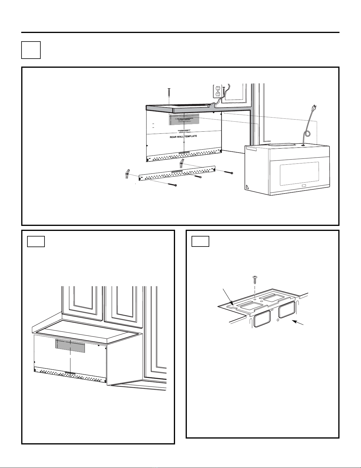
PREPARING THE REAR WALL
FOR OUTSIDE BACK EXHAUST
B1.
You need to cut an opening in the rear wall for
outside exhaust.
•Read the instructions on the REAR
WALL TEMPLATE.
•Tape it to the rear wall.
•Cut the opening, following the instructions of the
REAR WALL TEMPLATE.
B2.
OUTSIDE BACK EXHAUST (Horizontal Duct)
B
Blower Plate
REMOVE BLOWER PLATE
B2. Remove Blower Plate
3/8"TO EDGE
NOTE:IT IS VERY IMPORTANT TO
READAND FOLLOW THE DIRECTIONS
INTHE INSTALLATION INSTRUCTIONS
BEFOREPROCEEDING WITH THIS
REARWALL TEMPLATE.
ThisRear Wall Template serves to position the bottom
mountingplate and to locate the horizontal exhaust
outlet.
1.Use a level to check that the template is positioned
accurately.
2.Locate and mark at least one stud on the left or
rightside of the centerline.
Itis important to use at least one wood
screwmounted firmly in a stud to support the weight
ofthe microwave. Mark two additional, evenly spaced
locationsfor the supplied toggle bolts.
3.Drill holes in the marked locations. Where there is
astud, drill a 3/16" hole for wood screws. For holes
thatdo not line up with a stud, drill 5/8" holes for
togglebolts.
DONOT INSTALL THE MOUNTING PLATE
ATTHIS TIME.
4.Remove the template from the rear wall.
5.Review the Installation Instruction book for your
installationsituation.
Locateand mark holes to align with holes in the
mountingplate.
IMPORTANT:
LOCATEAT LEAST ONE STUD ON EITHER SIDE OF
THECENTERLINE.
MARKTHE LOCATION FOR 2 ADDITIONAL, EVENLY
SPACEDTOGGLE BOLTS IN THE MOUNTING PLATE
AREA.
Locateand mark holes to align with holes in the
mountingplate.
IMPORTANT:
LOCATEAT LEAST ONE STUD ON EITHER SIDE OF
THECENTERLINE.
MARKTHE LOCATION FOR 2 ADDITIONAL, EVENLY
SPACEDTOGGLE BOLTS IN THE MOUNTING PLATE
AREA.
Trimthe rear wall template along the dotted line.
Trimthe rear wall template along the dotted line.
12"
4"
Darlevuelta a la hoja para consultar la
versiónen Español.
Make sure the motor wiring has
EN-16
3/8"TOEDGE
NOTE:IT IS VERY IMPORTANT TO
READAND FOLLOWTHE DIRECTIONS
INTHE INSTALLATION INSTRUCTIONS
BEFOREPROCEEDING WITH THIS
REARWALL TEMPLATE.
ThisRearWall Template serves to position thebottom
mountingplate and to locate the horizontal exhaust
outlet.
1.Use a level to checkthat the template is positioned
accurately.
2.Locate and markat least one stud on theleft or
right side of the centerline.
Itis important to use at leastone wood
screwmountedfirmly in a stud to support the weight
ofthe microwave. Mark twoadditional, evenly spaced
locationsforthe supplied toggle bolts.
3.Drill holes in the marked locations. Where there is
a stud, drilla 3/16" hole for wood screws. For holes
that do not line up with a stud, drill 5/8" holesfor
toggle bolts.
DONOT INSTALLTHEMOUNTING PLATE
ATTHIS TIME.
4.Remove the template fromthe rearwall.
5.Reviewthe Installation Instruction book for your
installation situation.
Locateand mark holes to align with holes in the
mountingplate.
IMPORTANT:
LOCATEAT LEAST ONESTUD ON EITHER SIDE OF
THECENTERLINE.
MARKTHE LOCATION FOR 2 ADDITIONAL, EVENLY
SPACEDTOGGLE BOLTS IN THE MOUNTING PLATE
AREA.
Locateand markholes to align with holes in the
mountingplate.
IMPORTANT:
LOCATEAT LEAST ONE STUD ON EITHER SIDE OF
THECENTERLINE.
MARKTHE LOCATIONFOR 2 ADDITIONAL, EVENLY
SPACEDTOGGLE BOLTS IN THE MOUNTING PLATE
AREA.
Trimthe rear wall template along the dotted line.
Trimthe rear wall template along the dotted line.
12"
4"
Darlevueltaala hojapara consultar la
versiónen Español.
24"
24"
ATTACH THE MOUNTING
PLATE TO THE WALL
B3.
•Read the instructions on the TOP CABINET
TEMPLATE.
•Tape it underneath the top cabinet.
•Drill the holes, following the instructions on the
TOP CABINET TEMPLATE.
CAUTION: Wear safety goggles when drilling holes
in the cabinet bottom.
Wall
Mounting
Plate
Spacing for Toggles More
Than Wall Thickness
Toggle
Bolt
Toggle Wings
To use toggle bolts:
Bolt End
Installation Instructions
Attach the plate to the wall using toggle bolts.
At least one wood screw must be used to attach
the plate to a wall stud.
Remove the toggle wings from the bolts.
Insert the bolts into the mounting plate through
the holes designated to go into drywall and reattach
the toggle wings to 3⁄4″(19 mm) onto each bolt.
1
2
Place the mounting plate against the wall and
insert the toggle wings into the holes in the wall
to mount the plate.
NOTE: Before tightening toggle bolts and wood
screw, make sure the bottom of the mounting plate
touch the bottom of the cabinet when pushed flush
against the wall and that the plate is properly
centered under the cabinet.
CAUTION: Be careful to avoid pinching fingers
between the back of the mounting plate and the wall.
Tighten all bolts. Pull the plate away from the wall
to help tighten the bolts.
3
4
2
1Remove and save screw that holds blower motor
to microwave.
ADAPTING MICROWAVE
BLOWER FOR OUTSIDE
BACK EXHAUST
B5.
End B
End A
will extend far enough to allow you to adjust
the blower unit.
Back of
Microwave
Blower Motor
Blower Motor
Screw
Forward
Openings Facing
Carefully pull out the blower unit. The wires
Before: Fan Blade
EN-17
USE TOP CABINET TEMPLATE
FOR PREPARATION OF TOP
CABINET
B4.
You need to drill holes for the top support screws and
a hole large enough for the power cord to fit through. Back of
Microwave
Roll the blower unit 90°
Back of
Microwave
3Before Rotation After Rotation

Attach the exhaust adaptor to the rear of the
oven by sliding it into the guides at the top
center of the back of the oven.
AFTER: Fan Blade
Openings Facing Back
Place the blower unit back into the opening.
Replace the blower plate in the same position
as before with the screw. Make sure the screw
is tight.
Roll the blower unit 90° so that fan blade
openings are facing out the back of the
microwave.
ADAPTING MICROWAVE
BLOWER FOR OUTSIDE
BACK EXHAUST (cont.)
B5.
Rotate blower unit counterclockwise 180°.
Before Rotation After Rotation
Gently remove the wires from the grooves.
Reroute the wires through grooves on other side
of the blower unit.
Before Rerouting After Rerouting
Wires Routed Through Right Side Wires Routed Through Left Side
Back of
Microwave Back of
Microwave
Blower Plate
Blower Motor
Screw
Secure the blower unit to the microwave with
the original screw.
Before Rolling After Rolling
Back of
Microwave
End A
End B
Back of
Microwave
Back of
Microwave
CAUTION: Do not pull or stretch the blower
unit wiring. Make sure the wires are not
pinched, and that they are properly secured.
NOTE: The blower unit exhaust
openings should match exhaust
openings on rear of microwave oven.
Installation Instructions
Push in securely until it is in the lower locking
tabs. Take care to assure that the damper hinge
is installed so that it is at the top and that the
damper swings freely.
Guide
Guide
Adaptor
Locking Tabs
Back of
Microwave
4
5
6
11
EN-18
Back of mircrowave
Knockout Plates:
Snip all 4 webs on
each knockout panel
and remove the metal
knockouts for rear airflow.
Please take care to
remove any sharp edges
created from removing
the knockout plates.
7
8
9
10
with snips. (For some models)
Remove the knockout plates in the back of the unit

Attach the microwave oven to the top cabinet.
Installation Instructions
3
MOUNT THE MICROWAVE
OVEN
B6.
FOR EASIER INSTALLATION AND PERSONAL
SAFETY, WE RECOMMEND THAT TWO PEOPLE
INSTALL THIS MICROWAVE OVEN.
NOTE: If your cabinet is metal, use the nylon
grommet around the power cord hole to prevent
cutting of the cord.
NOTE: We recommend using filler blocks if the
cabinet front hangs below the cabinet bottom shelf.
IMPORTANT: If filler blocks are not
used, case damage may occur from
overtightening screws.
Insert a self-aligning screw through top center
cabinet hole. Temporarily secure the oven by
turning the screw at least two full turns after the
threads have engaged. (It will be completely
tightened later.) Be sure to keep power cord
tight. Be careful not to pinch the cord, especially
when mounting flush to bottom of cabinet.
8
7
5
Cabinet Front
Cabinet Bottom Shelf
Tighten the outer two screws to the top of the
microwave oven. (While tightening screws, hold
the microwave oven in place against the wall and
the top cabinet.)
Filler Block
Microwave Oven Top
Equivalent
to Depth
of Cabinet
Recess
Insert 2 self-aligning screws
through outer top cabinet
holes. Turn two full turns on
each screw.
packed with the microwave.
Self-Aligning Screw
4
2Rotate front of oven
up against cabinet
bottom.
NOTE: When mounting the
microwave oven, thread
power cord through hole in
bottom of top cabinet. Keep
it tight throughout Steps
1–3. Do not pinch cord or
lift oven by pulling cord. Lift microwave, tilt it
forward, and hook
slots at back bottom
edge onto four lower
tabs of mounting
plate.
1
Install grease filters. See the Use &&&&and Care
EN-19
IMPORTANT: Do not grip or use the handle
or heat shield during installation. Do not
remove the cardboard spacers between the
heat shield and door.
INSTALLATION OVERVIEW
C1. Attach Mounting Plate to Wall
C2. Prepare Top Cabinet
C4.
C5. Mount the Microwave Oven
IMPORTANT NOTES:
•Make sure the screws for the blower motor and blower
plate are securely tightened when they are reinstalled.
This will help to prevent excessive vibration.
•Make sure the motor wiring has been properly routed
and secured, and that the wires are not pinched.
Installation Instructions
Place the mounting plate against the wall and
insert the toggle wings into the holes in the wall
to mount the plate.
NOTE: Before tightening toggle bolts and wood
screw, make sure the bott m of the mounting plate
touch the bottom of the cabinet when pushed flush
against the wall and that the plate is properly
centered under the cabinet.
CAUTION: Be careful to avoid pinching fingers
between the back of the mounting plate and the wall.
Tighten all bolts. Pull the plate away from the wall
to help tighten the bolts.
4
3
ATTACH THE MOUNTING
PLATE TO THE WALL
C1.
Attach the plate to the wall using toggle bolts.
At least one wood screw must be used to attach
the plate to a wall stud.
Remove the toggle wings from the bolts.
Insert the bolts into the mounting plate through
the holes designated to go into drywall and
reattach the toggle wings to 3⁄4″(19 mm) onto
each bolt.
1
Wall
Mounting
Plate
Spacing for Toggles
More Than Wall
Thickness
Bolt End
Toggle
Bolt
Toggle Wings
To use toggle bolts:
2
RECIRCULATING (Non-Vented Ductless)
C
Install or change Charcoal Filter
C3. Check Blower Plate
NOTE:
Cabinet
Cabinet
If the cabinet depth including the cabinet doors
is more than 13""'' then the unit must be spaced
out from wall using adequate materials supporting
150 Ibs to allow proper top vent air exhaust/intake.
o
EN-20
3/8"TO EDGE
NOTE:IT IS VERY IMPORTANT TO
READAND FOLLOW THE DIRECTIONS
INTHE INSTALLATION INSTRUCTIONS
BEFOREPROCEEDING WITH THIS
REARWALL TEMPLATE.
ThisRear Wall Template serves to position thebottom
mountingplate and to locate the horizontal exhaust
outlet.
1.Use a level to checkthat the template ispositioned
accurately.
2.Locate and mark at least one studon theleft or
rightsideofthe centerline.
Itisimportant to use at leastone wood
screwmountedfirmly ina stud to support the weight
ofthe microwave. Marktwoadditional, evenly spaced
locationsfor the supplied toggle bolts.
3.Drill holes in the marked locations.Where there is
astud,drilla 3/16" holeforwood screws. For holes
that do not line up with a stud, drill 5/8"holes for
togglebolts.
DONOT INSTALLTHE MOUNTING PLATE
ATTHIS TIME.
4.Removethe template fromthe rearwall.
5.Review the Installation Instruction book for your
installationsituation.
Locateand markholes to align with holes in the
mountingplate.
IMPORTANT:
LOCATEAT LEAST ONESTUD ON EITHER SIDE OF
THECENTERLINE.
MARKTHE LOCATION FOR 2 ADDITIONAL, EVENLY
SPACEDTOGGLE BOLTS IN THE MOUNTING PLATE
AREA.
Locateand markholes to align with holes in the
mountingplate.
IMPORTANT:
LOCATEAT LEAST ONE STUD ON EITHER SIDEOF
THECENTERLINE.
MARKTHE LOCATIONFOR 2 ADDITIONAL, EVENLY
SPACEDTOGGLE BOLTS IN THE MOUNTING PLATE
AREA.
Trimthe rear wall template along the dotted line.
Trimthe rear wall template along the dotted line.
12"
4"
Darlevuelta a lahojapara consultar la
versiónenEspañol.
Other manuals for F2413MV5SS
1
Table of contents
Other Forte Microwave Oven manuals


Popular Microwave Oven manuals by other brands


GE
GE Profile Spacemaker PVM1870SMSS Dimensions and installation information

Tower Hobbies
Tower Hobbies T24002 Safety and instruction manual

KitchenAid
KitchenAid KMCS1016 Use & care guide

Panasonic
Panasonic NN-S245 Operation manual

Electrolux
Electrolux EI27MO45GS installation instructions

Sharp
Sharp R-793M quick start guide


