Fortin Bones User manual
1
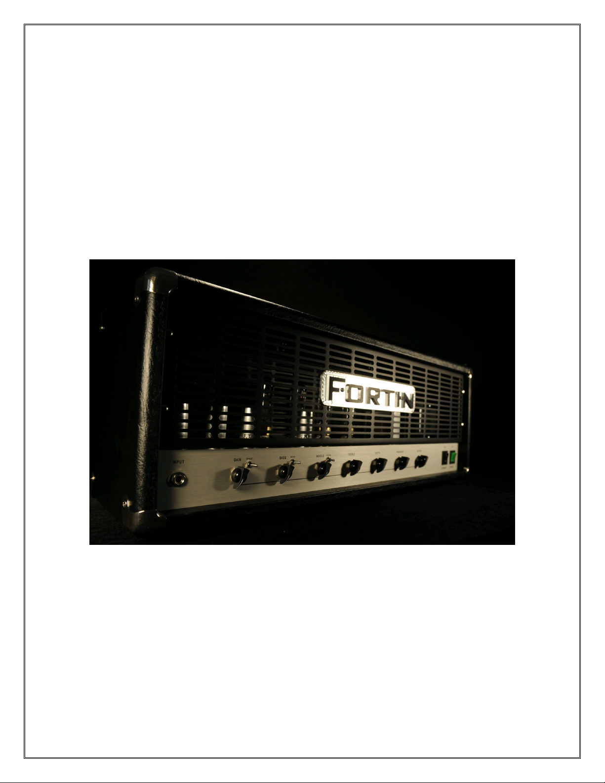
BONES
All Tube Guitar Amplifier
By Fortin Amplification, Inc.
Owners Manual
© 2008 FORTIN AMPLIFICATION, INC.

2
Congratulations and than you for purchasing the Fortin BONES guitar amplifier! As the
name implies the BONES is just that, a stripped down “bare bones” amplifier. With
modern styling and a simple & intuitive front panel layout, BONES is extremely versatile
and completely inspiring from the first note played. It retains all the detail of your
instruments and playing dynamics as well as front-end coloration from stomp box pedals.
Ta e some time to familiarize yourself with this manual and discover all the features
BONES has to offer. Please do not hesitate contacting us with any questions you might
have.
Cheers,
Mike Fortin
FORTIN AMPLIFICATION, INC.
Whitby, Ontario Canada
www.fortinamps.com

3
IMPORTANT AFETY IN TRUCTION
Your Fortin amplifier is a professional instrument. Please use common sense, read,
understand and follow all instructions in this manual and warnings on the bac of the
amplifier.
► Do not store or operate this amplifier in or near moist/wet areas.
► Do not place any objects filled with liquids on or near the amplifier.
► Do not obstruct the air space in front or behind the amplifier.
► Do not use the AC power supply cord if it has been pinched or abraded.
► Do not defeat the safety feature of the polarization blade or ground pin of the AC
power supply cord or inlet.
► Do not place this amplifier near heat sources such as heat registers, radiators or
other products that produce heat.
► Always insure that the amplifier is properly grounded. Always unplug the AC power
supply cord before moving amplifier, removing any fuses/tubes/chassis. Always
replace fuses with correct type and rating.
► The AC power supply cable should be unplugged from the outlet when left unused for
long periods of time, or during electrical storms.
► No user serviceable parts inside. Refer servicing to qualified personnel only.
► Fortin amplifiers and spea er enclosure systems are capable of producing high sound
pressure levels. Exposure to these levels may cause temporary or permanent hearing
damage.
4
BONE Functions
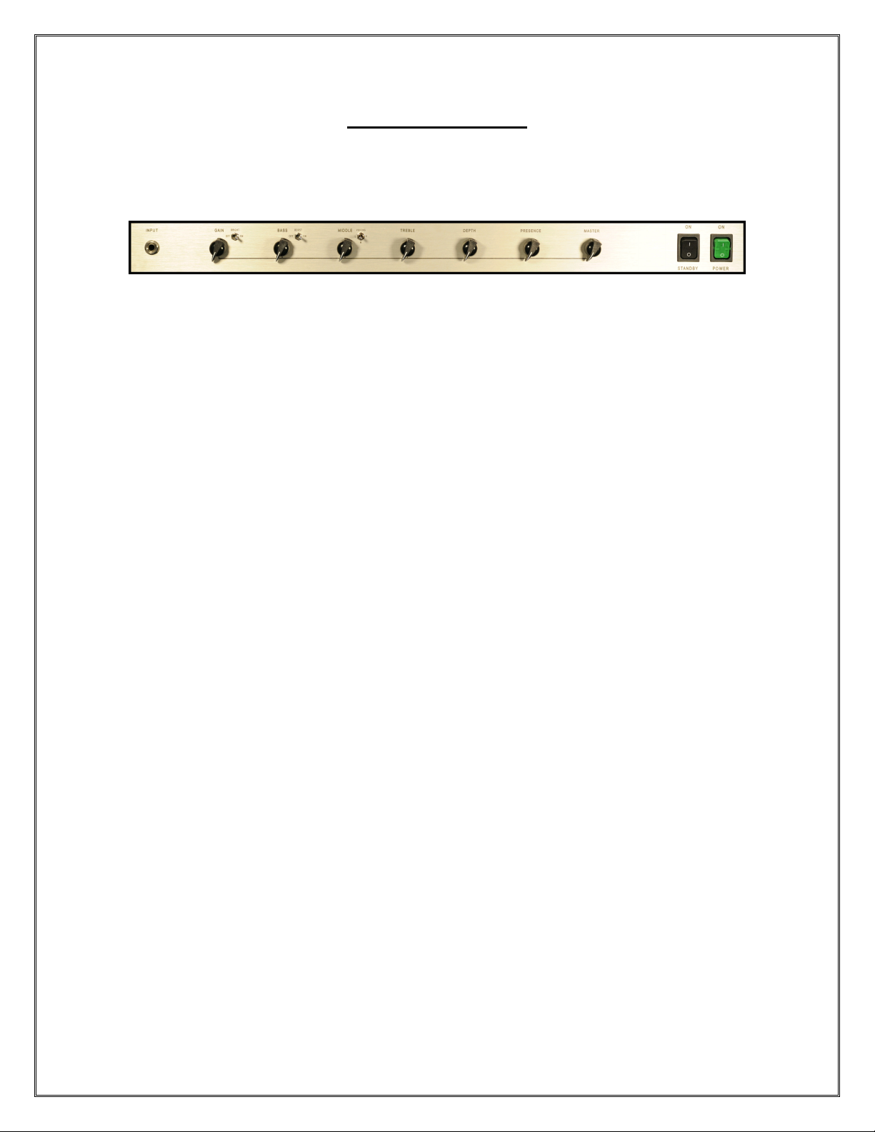
FRONT PANEL, LEFT TO RIGHT
1. INPUT – Plug in your guitar or stompbox here.
2
.
GAIN
–
Sets the amount of overdrive.
3.
BRIGHT
–
High frequency boost that becomes less active as GAIN is increased.
4. BA – Passive/Interactive low frequency equalization.
5. BOO T – Preset amount of gain boost. Active in VOICING M & H only.
6. MIDDLE – Passive/Interactive midrange frequency equalization.
7. VOICING L/M/H – Selects amount of tube gain stages. L = 2 stages, M = 3 stages,
or H = 4 stages.
8. TREBLE – Passive/Interactive high frequency equalization.
9. DEPTH – Power amp control of low frequency interaction between amplifier and
spea ers.
10. PRE ENCE – Power amp control of high frequency variable feedbac .
11. MA TER – Controls the overall output volume of the amp post EQ.
12. TANDBY – Turns on high voltage to the tubes.
13. POWER – On/Off switch for the mains electric power to the amplifier.

5
REAR PANEL, LEFT TO RIGHT
1. MAIN FU E – Protection for AC power faults.
2. MAIN INPUT – AC wall power via IEC cord to a grounded outlet.
3. HT FU E – Protection for high voltage faults.
4. MIDI IN* – Connects to external device via MIDI OUT or THRU. 7 connector with
outside pin 1 and pin 7 supplying 9VAC at 1.5A to power external Midi pedals.
5. MIDI THRU* – Routes Midi to other devices.
6. FOOT WITCH* – Connect your footswitch here.
7. BIA CONTROL – Bias adjust pots and test points. Tubes fused in pairs at T.5A.
8. .LEVEL* – FX loop send level.
9. FX LOOP* – FX loop on or off.
10. END* – Send jac connects to effects input.
11. ERIE / PARALLEL* – Selects the FX loop operation.
12. RETURN* – Return jac connects to effects output.
13. LEVEL L / H* – Sets recovery gain structure for FX Loop. Set to L for rac effects
and H for stomp box pedals.
14. R.LEVEL* – Effects level in SERIES and effects mix in PARALLEL.
15. LINEOUT* – Unbalanced signal tapped off the output transformer. Use a shielded
cable to send a signal to the effects rac , mixer input, or to another amp’s input or
effects return to slave.
16. LEVEL* – Lineout adjustable line level.
17. LOUD PEAKER - Paralleled wired jac s for 1 or 2 - 16 ohm, 1 or 2 - 8 ohm and
single 4 ohm cabinets.
* Optional

6
BONE Operation
INITIAL ET UP
First, start off by connecting a good quality spea er cable to one of the five, self-
explanatory LOUDSPEAKERS jac s on the bac of the BONES amp, then to a spea er
cabinet. Next, if you have the optional footswitch / Midi, connect them up and set the
front BOOST switch to the off position and the VOICING L/M/H switch to the M
position; otherwise disregard this step. Before connecting the AC power supply cable to
the MAINS INPUT, set the POWER and STANDBY switch in the off or down positions.
Now, plug in the AC power supply cable to amplifier’s MAINS INPUT and AC outlet.
Put the POWER switch in the on or up position. Ta e the next minute or so to set the
BASS, MIDDLE, TREBLE controls to 12 o’cloc , BRIGHT off, BOOST off, VOICING
L/M/H to L, GAIN and MASTER controls to zero. Plug in a good quality shielded
instrument cable from your guitar and or stomp box pedal(s) to the INPUT jac on front
of the amplifier. At this point you can place the STANDBY switch in the up position.
Now we are ready to explore the range of tones available in the BONES amplifier.
TONE EXPLORATION
The BONES amplifier was developed to deliver an astonishing array of tones in a simple
and intuitive pac age. Beside the use of top quality parts, special attention was given to
the grounding system that gives the BONES tons of detail to the tone. This is why the
amplifier loves pedals and different guitars so much. You can dial in luscious, span y
clean to the perfect crunch with plenty of girth to searing, cabinet exploding overdrive.
All these tones are possible from bedroom level to the MASTER volume wide open. It
truly is li e having 3 completely different amplifiers at your fingertips. So let’s go over
some of the features in more detail. Note that the control setting suggestions may vary
due to the different type of guitars and pic up configurations used.
VOICING L: This switch sets up the BONES with 2-12AX7 preamp gain stages. This is
excellent for players that love that wide open, late 60’s British vibe. This is the lowest
gain setting of the BONES. The BOOST switch is inactive in this mode. With the GAIN
control setting at 11 o’cloc and lower, in conjunction with MASTER volume set beyond
2 o’cloc , will give you some stellar clean tones with loads of dynamics. The BRIGHT
switch engages a treble boost and the amount is dependent on the GAIN control setting.
Higher settings of the GAIN control, less effect the BRIGHT switch will have and the
opposite with lower GAIN control settings. For a great plexi type of tone, set the
MASTER completely open in the cloc wise position, set the GAIN control at 2 o’cloc ,
BRIGHT switch ON, tone stac as desired, Depth off and Presence at 1 o’cloc .
VOICING M: This switch sets up the BONES with 3-12AX7 preamp gain stages. This
setting gets into some meaty overdriven tone while still remaining very open sounding.
Placing the BOOST switch ON adds more gain and girth to the tone. The BRIGHT
switch functions the same as described above but now with the added tube stage, the
upper harmonic quality has shifted. Varying the GAIN control will give you different
degrees of attac and sharpness to the tone. Place the BRIGHT switch off and the tone
gets rounder and warmer sounding that stays even with the movement of the GAIN

7
control. Higher settings of the GAIN control will give you more distortion and sustain. It
will have enough gain for most lead wor with a nice balance of punchy percussiveness.
This setting also cleans up nicely when you roll bac your guitar’s volume.
VOICING H: This switch sets up the BONES with 4-12AX7 preamp gain stages. This
setting gets you into the soaring modern high gain tones. Placing the BOOST switch on
adds even more gain and thic ness. The BRIGHT switch adds the cut and teeth to the
tone and as stated above, is dependent on the GAIN control setting. Higher settings of the
GAIN control with the BOOST and BRIGHT switch ON, will bring in a singing lead
tone with the perfect balance of compression without losing note definition. Setting the
GAIN control to 12 o’cloc with all the switches on, tone stac as you wish, DEPTH at
11 o’cloc , PRESENCE at 2 o’cloc , and MASTER volume at 3 o’cloc gives you a
seriously vicious rhythm and lead tone in one that really hits you in the chest.
DEPTH, PRESENCE & MASTER: These are controls for the power amp section of the
BONES. The DEPTH control should be used sparingly to eep the amp’s bass response
tight. Higher settings will give you a looser low end tone. The PRESENCE control from
the off position to 1 o’cloc will give you an imaging effect. Higher settings will give
you a sharper focus for extra cut. As the MASTER is turned up, it will affect the DEPTH
and PRESENCE. It is best to thin of them all together when ma ing adjustments as they
are interactive.
As you can see, by experimenting with combinations of the control settings plus all the
different output tubes that the BONES can accept, you can cover an astonishing array of
tones. To embellish this entirely new found tonal palette, let’s move on to the optional
FX Loop.
FX LOOP *
This all-tube, full audio bandwidth effects loop is designed to be completely transparent.
You can use stomp box pedals or rac effects in this loop. Set the FX LOOP switch to the
OFF position for remote switching. Even though the loop is completely transparent, the
purists can have peace of mind nowing that when the FX LOOP switch is OFF, it is
completely ta en out of the signal path via relay. This loop allows you to operate it as a
series or parallel effects loop via the SERIES/PARALLEL switch.
SERIES FX LOOP:
This basically wor s as an insert patch point. The SEND jac plugs into the effects unit’s
input jac . The RETURN jac plugs into the effects unit’s output jac . The audio path of
the amplifier is interrupted and 100% of the signal is being sent to the SEND jac . It must
be noted that when nothing is plugged into the SERIES selected FX LOOP and the FX
LOOP switch is in the ON position, no sound will be heard out of the spea ers. You must
complete the audio path with an effects unit or patched instrument cable. The S.LEVEL
control is used to adjust the amount of signal being sent to an effects unit. With stomp
box pedals there are usually no input level indicators. In this case you will have to use
your ears to set the S.LEVEL. Set the S.LEVEL up to the maximum setting just before
you start to hear the undesirable front end clipping of your effects pedal. This setting of
the S.LEVEL will usually be quite low for pedals. Setting the S.LEVEL for rac units is

8
easier since they have input indicators. You will have to experiment with your rac
effects to obtain the best signal to noise ratio by trying different S.LEVEL & R.LEVEL
settings in conjunction with the input & output level controls of your rac effects unit. On
the R.LEVEL control, bring this up to match the signal level when the FX LOOP switch
is turned off (for footswitchable loop) or when the effects pedal is turned off. Toggle
bac and forth to set levels. Place the LEVEL switch in the L position for stomp box
effects. This will give the return side of the loop the ma e up gain it needs. Place the
LEVEL switch in the H position for rac effects units. This will give the return side of
the loop less gain because of the typical higher output levels of rac effects units.
PARALLEL FX LOOP:
This wor s as a side chain. Your original, dry tone is unaffected allowing you to mix in
the amount of effects. The SEND jac plugs into the effects unit’s input jac . The
RETURN jac plugs into the effects unit’s output jac . Unli e the SERIES setting of the
loop, when set to PARALLEL with nothing plugged into the loop, it will pass signal. The
S.LEVEL control is used to adjust the amount of signal being sent to an effects unit. With
stomp box pedals there are usually no input level indicators. In this case, again, you will
have to use your ears to set the S.LEVEL. Set the S.LEVEL up to the maximum setting
just before you start to hear the undesirable front end clipping of your effects pedal. This
setting of the S.LEVEL will usually be quite low for pedals. Setting the S.LEVEL for
rac units is easier since they have input indicators. You will have to experiment with
your rac effects to obtain the best signal to noise ratio by trying different S.LEVEL &
R.LEVEL settings in conjunction with the input & output level controls of your rac
effects unit. Place the LEVEL switch in the L position for stomp box effects. This will
give the return side of the loop the ma e up gain it needs. Place the LEVEL switch in the
H position for rac effects units. This will give the return side of the loop less gain
because of the typical higher output level of the rac effects units. In the PARALLEL
loop, the R.LEVEL control now acts as an effects mix control. It will bring in the effects
and mix it with the original unaffected signal. At higher S.LEVEL settings the effects
will become louder than the original unaffected signal if it is desired.
Things to keep in mind: When using effect units in the FX LOOP in PARALLEL mode,
you must set the effects unit’s mix control to 100%. By not doing so will cause phasing
cancellations. Using the FX LOOP in SERIES mode will send 100% of the amp’s signal
out of the SEND jac . Please use caution as to the quality of the effects unit you want to
put your entire tone through. This is a non “tone suc ing” loop. If transparency is not
achieved, then it is most li ely caused by improper setting or application of the FX loop.
The use of high quality, name brand patch cables for all FX loop applications is highly
recommended. Inexpensive, “no name” patch cables are often the cause of tone loss in
FX loop routing scenarios.
* Optional
9
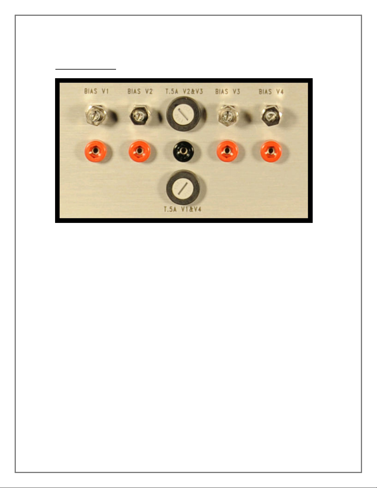
BIA CONTROL
This is a powerful feature and tool for exploring more tonal possibilities with the BONES
amplifier. You can mix and match different tube types together for an almost unlimited
range of tones. More on this later. Since there is individual bias adjustment for each tube,
there is no need to obtain matched tubes! BONES will accept EL34, 6CA7, KT77, 6L6,
5881, KT66, 6550, KT88, KT90, KT100 type tubes and any other derivations of the
above. The output power will range from 100 to 180 watts RMS depending on the output
tube selection. The added benefit of having output tubes fused in pairs is in case of tube
failure, you will be able to finish your gig. Only a small volume reduction and slight tonal
change will occur.
Biasing the BONES amp is simple and does not require removal of the chassis. You will
need a simple voltmeter or digital multimeter set to the lowest DC voltage range,
typically 200mV (millivolts). Please note that some meters display may indicate 25.0 for
25 mV and others may display .025 for 25 mV. Make sure you know your meter and refer
back to the meter’s owners manual to be certain. Then follow the these directions:
1. Unplug any cords from the INPUT, ma e sure the MASTER volume control is
turned all the way down, countercloc wise. Unscrew the loc nuts on all the bias
pots located on the rear panel, then turn all the bias controls all the way down,
countercloc wise. Connect a load to the appropriate spea er jac , plug in the AC
cord and turn on the amplifier. Wait a few minutes then put the STANDBY
switch in the up position.
2. Put the blac negative probe lead of your meter into the blac tip jac . Place the

10
positive red probe lead in the red tip jac of BIAS V1. Referring to the
recommended bias settings below, slowly adjust the corresponding bias pot while
paying attention to its sensitivity. Ma e a note of your bias setting if you are using
2 or 4 of the same tubes.
3. Repeat step 2 for BIAS V2, BIAS V3, & BIAS V4. Then rechec and ma e
further adjustments as necessary.
4. Once the bias is set, tighten down the loc nuts on the bias trim pots, but not too
tight. Now you are ready to play.
Recommended Bias ettings:
EL34/6CA7/KT77 25mV to 35mV
6L6 /5881/KT66 30mV to 42mV
6550 35mV to 51mV
KT88 44mV to 61mV
Note: The upper range of the recommended bias settings should be considered a
maximum setting. Feel free to experiment within the given ranges to suit your taste. It is
normal for tubes to drift a little, especially when they are new, and will stabilize after a
few hours of use. Also, bias will drift with variations in AC line voltage. This is not a big
deal so don’t get obsessed by constantly chec ing the bias to eep it at your chosen
settings. To balance out the currents of the output tube when using 4 of the same type of
output tubes, place one meter probe (blac or red) into BIAS V1 red tip jac then the
other meter probe into the BIAS V4 red tip jac . Then adjust either one of the
corresponding bias pots to get a 0 reading on your meter. Repeat the above for BIAS V2
and BIAS V3. If you are using 2 different output tube types, (e.g. 2-KT88 and 2-EL34),
place the 2-KT88s in either V1 and V4 or V2 and V3 positions, then the 2-EL34s in the
remaining positions and follow the above procedure to balance out the currents. Special
note for the adventurous souls: When using a different tube type in each position, please
eep the imbalance to a maximum of + or - 15mV DC. Using this simple formula of
(BIAS V1 + BIAS V2) – (BIAS V3 + BIAS V4) = maximum plus or minus 15mV DC
will ensure optimum performance. Nothing will happen to the amp if it exceeds this value
but you may experience an audible hum in the output and loss of low end response at
extreme volume settings. Mixing different tube types is an easy and fun way to combine
characteristics of your favorite tubes for a “best of both worlds” approach. Although tone
is subjective, all tubes have their own distinct sonic character and “feel” that you can use
to your advantage in further fine tuning your BONES amplifier. Ta ing this approach one
step further, you can also experiment with different preamp tubes.
11
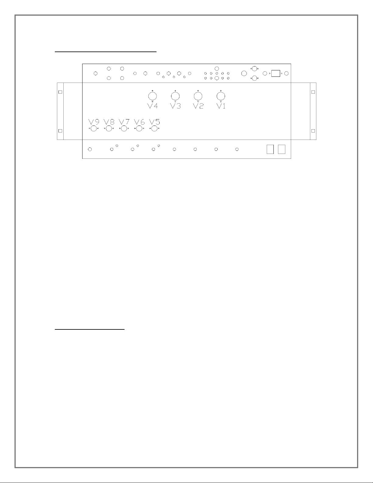
TUBE LAYOUT & FUNCTION
V1 - V4 Class A/B power output tubes: EL34, 6CA7, KT77, 6L6, 5881, KT66,
6550, KT88, KT90, KT100
V5 Phase Inverter: 12AX7
V6* FX Loop: 12AT7 only.
V7 4
th
gain stage & Cathode follower: 12AX7
V8 2
nd
and 3
rd
gain stage: 12AX7
V9 1
st
gain stage: 12AX7
* Optional
TIP & IDE NOTE
If you want a half power function without the removal of tubes, simply pull out either the
T.5A V1&V4 or T.5A V2&V3 fuse located with the bias controls. The transformers
were designed to ta e serious abuse. No need to do math to figure out the correct
impedance when doing so. Experiment with different impedances and go with what
sounds best to you. If you wish to eep the intended sonic design, then select the
amplifier’s impedance at ½ (half) the value of the spea er load when in half power mode.
For example, a 16 ohm spea er cabinet plugs into the 8 ohm LOUDSPEAKERS jac of
the amplifier. You can also turn the optional FX LOOP into a volume boost, a second
master volume if you will, by ta ing a small instrument cable and jumping the SEND and
RETURN jac s in either SERIES or PARALLEL mode. Then using one or both controls,
engage the loop on and off to adjust your level of volume boost.

12
LIMITED WARRANTY
Subject to the obligations and exclusions listed below, this Fortin Amplification product
is warranted against manufacturing defects in materials and wor manship for the period
of 5 (five) years from the date of purchase, with the exception of the tubes, fuses and
spea ers where applicable, which carry a 90 day warranty. The warranty period starts on
the date of purchase by the original owner.
Obligations:
This warranty will be honored only on the presentation of the original proof of purchase.
Products are to be returned freight prepaid, to and from, Fortin Amplification. Warranty
repairs and must be authorized. Fortin Amplification is not liable for any freight or duty
charges (if applicable).
Exclusions:
This warranty shall not cover adjustment of user operated controls as explained in the
appropriate instruction manual, or products that have been altered or have missing, or
defaced serial numbers. This warranty shall not apply to the aesthetics of accessory items
including but not limited to, cabinets, cabinet parts, or nobs. This warranty does not
apply to unpac ing, setup, installation, or the removal and reinstallation of products for
repair. This warranty shall not apply to repair or replacements necessitated by any cause
beyond the control of Fortin Amplification including, but not limited to, any malfunction,
defects, or failure caused by or resulting from unauthorized service or parts, damaged or
bro en tubes, incorrect line voltage, improper maintenance, modification or repair by the
user, abuse misuse, neglect, accident, fire, flood, or other Acts of God. Fortin
Amplification does not authorize any party to assume for it any other obligation or
liability. In no event shall Fortin Amplification be liable for any damages arising from the
use of this product, or for any delay in the performance of this warranty due to causes
beyond our control.
© 2008 FORTIN AMPLIFICATION, INC. Whitby, Ontario Canada
www.fortinamps.com
Table of contents
Other Fortin Amplifier manuals


Popular Amplifier manuals by other brands


Origin Acoustics
Origin Acoustics SUBA500 installation manual

Altec Lansing
Altec Lansing 1698 SIGNAL PROCESSING manual

Analog Technologies
Analog Technologies AHVA2KV2X10MA manual

Radio Systems
Radio Systems MA-4 manual

Halcro
Halcro MC70 Schematic diagram

Interface Devices
Interface Devices AA-160 Installation, operation & maintenance manual