Fortis 6000 RT Manual

6000 RT
Remote Teller System
Installation and Service Manual
August 2016

Fortis Security Products
6000-RT Remote Teller System
Installation and Service Manual
Table Of Contents
6000RT Customer and Teller Dimensional Specifications Pg-1
Customer Service Door Removal Pg-2
Typical Installation Drawing Pg-3
6000RT Customer Island Detail Pg-4
Customer Mounting and Electrical Information Pg-5
Customer Turbine Installation Pg-7
Customer Audio Connections Pg-8
6000RT Teller Installation Drawings Pg-9
Teller Control Set-Up Pg-13
System Tubing Connections Pg-16
System Operational Sequence Pg-17
System Electrical Drawings Pg-18
Care and Maintenance Pg-22
Lane Station Installation Pg-23
Camera Installation Pg-24
Customer Part Breakdown Pg-25
Teller Part Breakdown Pg-29

13 5
16
"
46 13
16
"
13 1
16
"
12 3
4
"
7 15
16
"
20"
58 3
16
"
12 5
8
"
6000RT CUSTOMER UNIT
6000RT TELLER UNIT
1

REMOVE TWO
SCREWS
TURN CCW
TO UNLOCK
PULL OUT ON THE BOTTOM
OF PANEL AND THEN
DOWN TO REMOVE.
BECAREFUL OF THE WIRING
THAT IS ATTACHED TO THE
BACK OF THE PANEL
REMOVING SERVICE PANELS
PULL OUT ON THE BOTTOM
OF PANEL AND THEN
DOWN TO REMOVE.
BECAREFUL OF THE WIRING
THAT IS ATTACHED TO THE
BACK OF THE FRONT PANEL
LOCK VIEW
2

DRIVE-UP SYSTEM VERTICAL SECTION
3

6 1
2
"
16"
3 3
4
"
5 1
8
"
7 1
2
"
10 1
4
"
9 7
16
"
CARRIER TUBE CENTER LINE
1/4" DIAMETER CONCRETE
ANCHORS (4) PLCS.
26" 26"
6"
7 11
16
"
1 11
16
"
3 1
8
"
7 1
4
"
1 3
4
"
4" BOLLARD
(2) PLCS.
ELECTRICAL CONDUIT
LOCATION
IT IS RECOMMENDED THAT THE CONDUIT
THAT HAS THE 120 VOLT 20 AMP CIRCUIT
COME UP INTO THE BOTTOM OF A JUNCTION
BOX THAT IS MOUNTED FLAT ON THE ISLAND.
THEN A FLEXIBLE CONDUIT CAN BE RAN THRU
THE BASE OF THE UNIT TO THE JUNCTION BOX
WHICH IS TO BE MOUNTED TO THE INSIDE OF
THE RIGHT SIDE PANEL BELOW THE MOTOR ASSEMBLY.
MAKE SURE THE OUTLET DOES NOT INTERFERE WITH THE
REMOVAL AND INSTALLATION OF THE TURBINE ASSEMBLY.
TRAFFIC FLOW >>>>>>>>>
6000RT CUSTOMER
MOUNTING LOCATIONS
TRAFFIC FLOW >>>>>>>>>
CONDUIT AND BOLLARD LOCATIONS
CURB
4

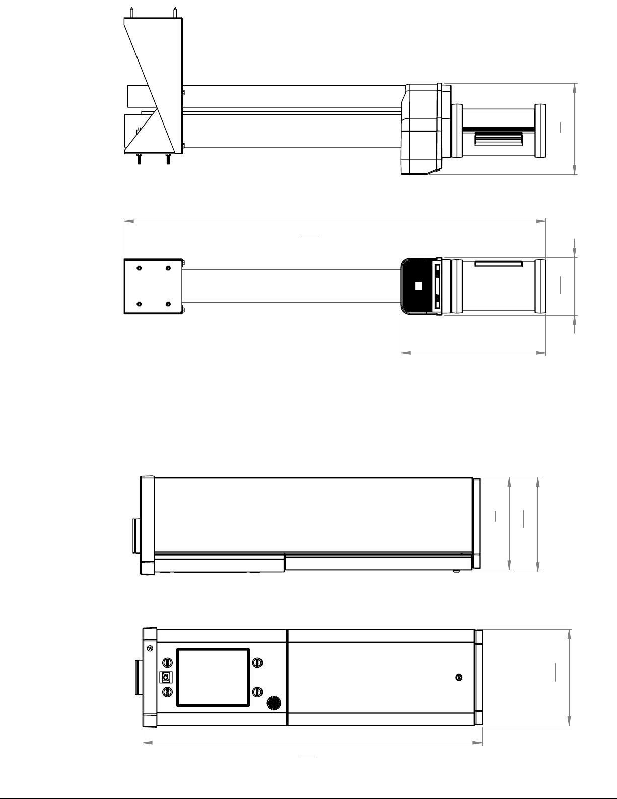
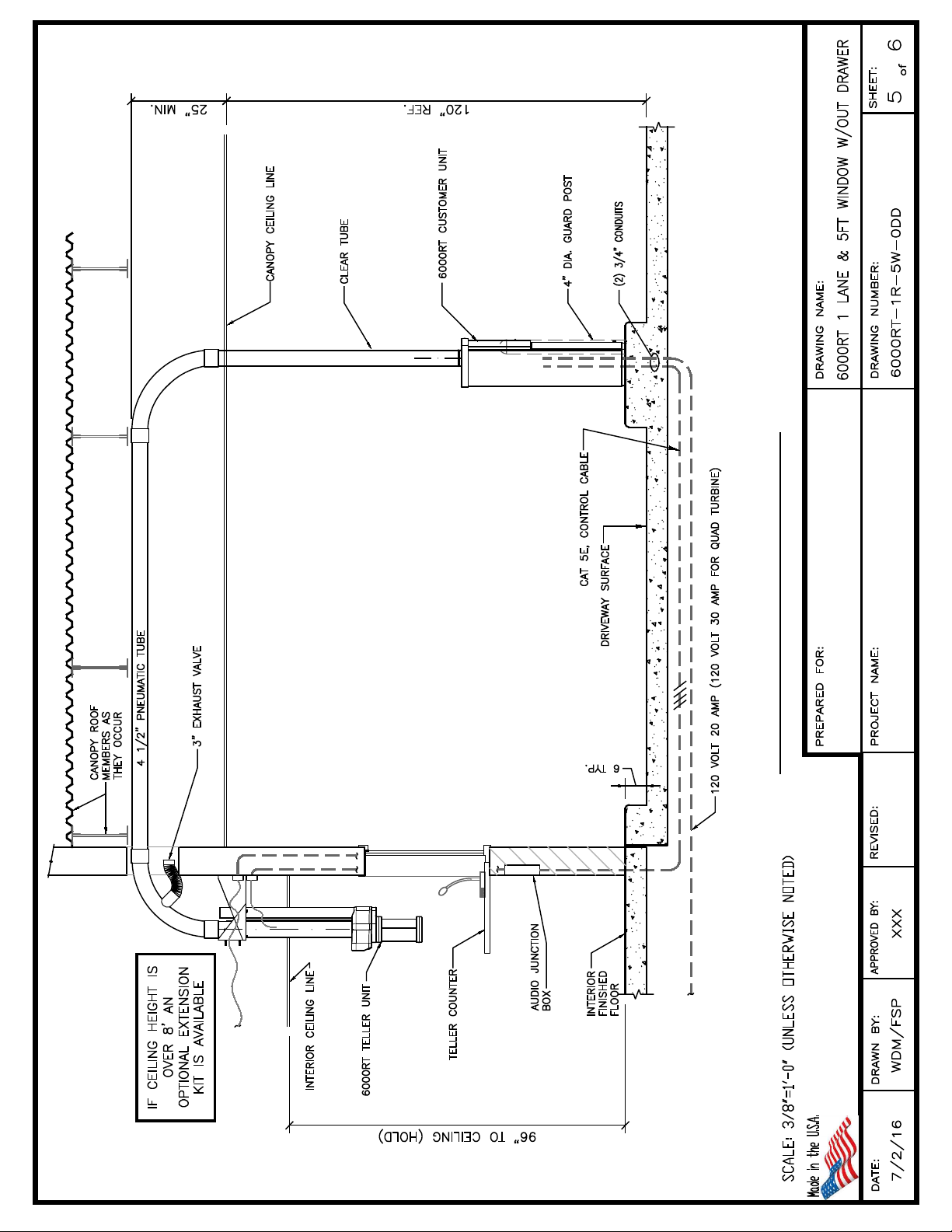
Mounting the Customer Unit
Locate Customer Unit on Island per detailed drawing. The front of the
unit should be five inches from the front of the curb. Remove the turbine
box by removing the flex hoses and lift out of unit. Mark the location of
the four mounting holes. Using four 3/8 “ dia concrete anchors secure
customer unit to island. Before final tightening of base anchors check
level of unit front to back and left to right. Make sure unit is not twisted
once fully tighten down to island
Electrical Connections
The main power connection is a 120V 20A circuit using a Nema L5-20P
cord end. The electrician should install an outlet for this style cord end
in a junction box that is mounted to the inside of the right side of the
cabinet. Make sure that this junction box and outlet do not interfere with
the removal and installation of the Turbine Assembly.
Note – If you are connecting conduits to the top of the unit.
DO NOT CUT ANY HOLES IN THE TOP. REMOVE THE TWO PLUGS IN
THE TOP. THESE HOLES ARE TAPPED SO THAT A ½” CONDUIT
CONNECTOR CAN BE THREADED INTO PLACE.
IT IS IMPORTANT THAT YOU ONLY USE THESE HOLES. THE
UNDERNEATH OF THE TOP IS CONSTRUCTED WITH A HAS A AIR
MANIFOLD MADE INTO IT. CUUTING INTO THE TOP WILL MAKE
THE UNIT UN-USABLE!
Each unit is shipped with a field wiring harness. The harness has eight
color coded wires which are to be connected to the field wiring cable that
runs between each station.
Connect these wires color for color.
5

6000RT ELECTRICAL INFORMATION
THREADED CONDUIT PORTS
FOR OVERHEAD ELECTRICAL INSTALLATION.
THESE PORTS ARE THREADED FOR 1/2"
CONDUIT CONNECTORS.
DO NOT CUT HOLES OR TRY TO ENLARGE
THESE PORTS. THE UNDER SIDE OF THE
TOP HAS AN AIR MANIFOLD MOLDED
INTO IT. CUTTING THE TOP IN ANYWAY MAY
RESULT IN AN AIR LEAK
E
OUTLET BOX SHOULD BE MOUNTED
15 INCHES FROM THE INSIDE OF THE
BASE TO THE BOTTOM OF THE BOX.
BOX SHOULD BE MOUNTED AGAINST
THE INSIDE OF THE RIGHT-SIDE PANEL
WITH IT AGAINST THE INSIDE OF THE
FRONT FLANGE.
BOX CAN NOT BE ANY DEEPER THAN
1 3/4 INCHES. YOU WILL HAVE TROUBLE
GETTING THE TURBINE ASSY IN AND OUT
IF THE ELECTRICAL BOX IS INSTALLED
INCORRECTLY!
JUNCTION BOX
ELECTRICAL CIRCUIT - 120 VOLT 20AMP DEDICATED CIRCUIT.
REQUIRES AN L5-20 RECEPTACLE
6

F
TURBINE INSTALLATION
ONCE THE TURBINE IS INSTALLED
THE HOSES WILL CONNECT AS
THEY LINE UP. THE BACK HOSE GOES
TO THE BACK PORT AND THE
FRONT HOSE GOES TO THE FRONT PORT
WHEN INSTALLING TURBINE
MAKE SURE THE FASTENERS
ON THE BOTTOM OF THE
TURBINE DROP DOWN INTO
THESE HOLES.
MAKE SURE THE BACK LEFT ANCHOR
DOES NOT KEEP THE TURBINE BOX
FROM SETTING FLAT ON THE BOTTOM
OF THE UNIT.
7

Audio System Connections
The microphones, speaker, and call buttons are wired into the main
harness and the pigtail is located near the electrical panel.
The microphone wires (two shielded cables):
Positive (red) negative (black) and common (bare)
The speaker wires ( red and black wires):
Positive (red) and negative (black)
The call button wires (blue and white):
Signal (blue) and common (white)
8

3100RT/ 5000RT/ 6000RT
MANUAL TELLER UNIT
SYSTEM BUTTON WILL
BE ILLUMINATED WHEN
SYSTEM IS READY FOR USE
RECALL BUTTON WILL BE
ILLUMINATED WHEN RECALL
OR CUSTOMER SEND SEQUENCE
IS ACTIVE.
INFORMATION AND SET-UP SCREEN
9

VENT TUBE
APPLY A SMALL AMOUNT
OF SILICONE AROUND THE
INSIDE OF THE EXPANDED
END BEFORE CONNECTING
TO TERMINAL VENT PORT
IF TERMINAL IS BEING USED
WITH A 3100 RT CUSTOMER
UNIT THIS PORT IS A PRESSURE
PORT AND MUST HAVE A
GOOD SEAL.
IF LONGER CARRIER AND VENT TUBES ARE NEEDED
CONTACT FORTIS SECURITY PRODUCTS FOR AVAILABILITY
INSTALL TUBES AS SHOWN
IF TUBES NEED TO BE TRIMMED
CUT THEM BEFORE INSTALLING
ON TELLER TERMINAL
MOUNTING HARDWARE
AND GASKET PACKAGED
SEPARATELY
INSTALL WIRE MOLD CENTERED
BEHIND CARRIER TUBE. LOCATE SO
THAT IT LINES UP OVER HOLE IN
REAR HOUSING. THIS WILL SERVE AS
A WIRE CHASE FOR YOUR CONTROL
CABLE
WIRE MOLD
PEEL AND STICK MOLDING
ON BEHIND CARRIER TUBE
TELLER INSTALLATION INSTRUCTIONS
10

A
B
A
C
MANUAL TELLER WALL MOUNT INSTALLATION
A-
ANCHOR BRACKET TO WALL WITH LAG-SCREWS. MAKE
SURE THERE IS BLOCKING IN THE WALL TO SUPPORT WEIGHT
OF TELLER UNIT
B-
TELLER HEIGHT CAN BE ADJUSTED UP OR DOWN BY
LOOSENING THE U CLAMPS AND SLIDING TELLER TO THE
CORRECT HEIGHT. TIGHTEN U CLAMPS ONCE ADJUSTED
C-
TELLER UNIT CAN BE ADJUSTED IN AND OUT BY LOOSENING
THESE BOLTS. TIGHTEN ONCE TELLER IS IN PROPER LOCATION
11

CARRIER TUBE
THIS TUBE IS A VENT TUBE
WHEN USED WITH A
5000RT/6000RT CUSTOMER
STATION
WHEN THIS TELLER IS USED
WITH A 3100 CUSTOMER
STATION IT IS A PRESSURE PORT
THAT MUST BE CONNECTED
TO THE REMOTE TURBINE
PRESSURE PORT.
12

9/64" ALLEN WRENCH IS
NEEDED TO REMOVE FOUR
SCREWS SECURING THE FRONT
PANEL ON THE TELLER UNIT
A
B
(A) FIELD WIRING CONNECTOR
(B) DOOR SWITCH CONNECTOR
TO ADJUST PARAMETERS BEND
A SMALL PAPERCLIP AS SHOWN
AND INSERT THE SMALL END THRU
THE APPROPRIATE SLOT
(DRAWING
ON THE RIGHT SHOWS A PICTURE OF
THE CONTROL MODULE KEYS THAT
ARE HIDDEN BEHIND THE ACCESS SLOTS)
*DO NOT USE A POINTED OBJECT!
MANUAL TELLER CONTROL SET-UP
THE POWER FOR THE CONTROL MODULE
IS 24VDC. THIS POWER IS SUPPLIED THRU
THE 8 CONDUCTOR CONTROL CABLE AND
COMES FROM THE CUSTOMER UNIT.
13

F
PRESS HERE TO GET TO
SET-UP SCREEN "1"
PRESS HERE UNTIL
PARAMETER IS BLINKING
PRESS HERE ONCE
PARAMETER IS BLINKING
THIS WILL TAKE YOU TO TIMER SCREEN
T1 X S +
T3 X S +
T4 X S +
T5 X S +
PRESS HERE TO SCROLL TO
THE TIMER THAT NEEDS ADJUSTING
ONCE THE APPROPRIATE TIMER
IS BLINKING PRESS HERE
T3 X S +
I1 06.500
I2 +0
□
T:00.000
WHEN THIS SCREEN APPEARS
THE FIRST 0 IN THE I1 LINE WILL
BE BLINKING. PRESS HERE TO
CHANGE VALUE
T3 X S +
I1 06.500
I2 +0
□
T:00.000
PARAMETER ADJUSTMENT PROCEDURE
5000RT-MAN
TELLER
SYSTEM READY
2015
TRANSACTIONS
00000
00000
PASSWORD
↑
STOP RUN
√
PARAMETER...
INFO
↓
START-UP SCREEN STAYS
ON FOR 10 SECONDS
NORMAL SCREEN WHEN
IN RUN MODE
SET-UP SCREEN "1"
TIMER SCREEN
PRESS HERE TO MOVE
LEFT AND RIGHT
PRESS HERE TO INCREASE
OR DECREASE THE VALUE
WHERE THE CURSOR IS
14

ONCE YOU HAVE THE VALUE
SET PRESS HERE TO SAVE.
PRESS HERE TO GO BACK TO
THE TIMER LIST AFTER SAVING CHANGE
OR A TOTAL OF 3 TIMES TO GET BACK TO
THE TRANSACTION SCREEN
T3 X S +
I1 06.500
I2 +0
□
T:00.000
T1 X S +
T3 X S +
T4 X S +
T5 X S +
TIMER LIST
C1 N +
S 00001
□
C:00000
PARAMETER ADJUSTMENT PROCEDURE
TIMER SCREEN
T3 X S +
I1 06.500
I2 +0
□
T:00.000
TIMER SCREEN
TIMERS AND PARAMETERS
T1 -
DO NOT CHANGE
T3 - OUTBOUND RUN TIME
T4 -
DO NOT CHANGE
T5 - INBOUND RUN TIME
T7 -
DO NOT CHANGE
T8 -
DO NOT CHANGE
T9 -
DO NOT CHANGE
T11 -
DO NOT CHANGE
T12 -
DO NOT CHANGE
T15 - ANTI-CONDENSATION START DELAY*
T16 - ANTI-CONDENSATION SETTINGS - I1 = BLOWER ON TIME IN SECONDS
I2 = OFF TIME IN MINUTES BETWEEN BLOWER PULSES. FACTORY SETTING
IS I1 = 4 (SECONDS) I2 = 90 (MINUTES)
THIS FEATURE IS ONLY ACTIVE
WHEN SYSTEM SWITCH IS OFF*
PARAMETERS
C1 = ANTI-CONDENSATION ON OR OFF (00001 = OFF 00000 = ON)*
C2 = AUTOMATIC TEST CYCLE ON OR OFF (00001 = OFF 00000 = ON)
THIS FEATURE
IS ONLY ACTIVE WHEN SYSTEM SWITCH IS OFF*
C5 -
DO NOT CHANGE
C12 -
DO NOT CHANGE
C15 -
DO NOT CHANGE
WHEN USING THE TEST CYCLE FUNCTION REMEMBER TO SET C2 TO 00000 AND TURN THE
SYSTEM SWITCH OFF. WHEN CYCLE TEST IS COMPLETE CHANGE C2 BACK TO 00001 AND
CHANGE THE SYSTEM SWITCH TO ON FOR NORMAL OPERATION (NOT AVAILABLE ON 3100
MODEL SYSTEM)
* INDICATES FEATURE THAT IS NOT AVAILABLE ON 3100 MODEL
PARAMETER SCREEN
THE PARAMETER SCREEN WILL ADJUST JUST LIKE A TIMER
WITH THE EXCEPTION THAT YOU ARE CHANGING THE VALUE
OF "S" INSTEAD OF I1.
15

Tubing Installation
Customer Tubing Connections
Clear tubing attaches to the top of the customer unit using the provided
TU-12 adapter there is an oring on the tube stub up on the customer
unit. Use Vaseline to lubricate this oring before installing collar. At the
top of the clear tube use the trim ring (TU-009) at the ceiling opening and
the TU-19 adapter to attach the clear tubing to the PVC (TU-10 when
attaching to steel tubing). Make sure that you seal the adapters to the
tubing by applying a clear silicone around each end of the adapters after
they are installed.
Teller Tubing Connections
Use the TU-11 to attach the steel tube coming from the top of the teller
unit to the PVC tubing. (a steel clamp sleeve TU-014 when attaching to
steel tubing)
16

System Operational Sequence
Teller Send-
1. Close Teller Door to send carrier.
2. Vacuum turbine runs for a preset amount of time.
3. Customer door opens.
Teller Recall /Customer Send-
1. Customer door closes.
2. Pressure turbine runs for a preset amount of time.
3. Teller Door opens.
System On/Off-
1. On- Activates the system for normal operation.
2. Off- de-activates the system and enables the anti-condensation
feature.
17

DATEREV. NAME
CONTRACT :
CHANGES
DRAWING
REVISION
Document realized ith version:
0
User data 2
User data 1
07
0Budgie
10/16/2015
DOOR MOTOR ASSEMBLY
SOLIDWORKS Electrical
2016.0.3.12
3 2
J6
1456
S3
S4
S5
M
M3
DOOR MOTOR
C1
DOOR CLOSED
LIMIT SWITCH
DOOR OPEN
LIMIT SWITCH
LIMIT SWITCH
DOOR SAFETY
18
Other Fortis Digital Signage manuals