Advantech DS-570 User manual

User Manual
DS-570
Graphic-Optimized Digital
Signage Player Powered by
NVIDIA N14M

DS-570 User Manual ii
Copyright
The documentation and the software included with this product are copyrighted 2014
by Advantech Co., Ltd. All rights are reserved. Advantech Co., Ltd. reserves the right
to make improvements in the products described in this manual at any time without
notice. No part of this manual may be reproduced, copied, translated or transmitted
in any form or by any means without the prior written permission of Advantech Co.,
Ltd. Information provided in this manual is intended to be accurate and reliable. How-
ever, Advantech Co., Ltd. assumes no responsibility for its use, nor for any infringe-
ments of the rights of third parties, which may result from its use.
Acknowledgements
Award is a trademark of Award Software International, Inc.
IBM, PC/AT, PS/2 and VGA are trademarks of International Business Machines Cor-
poration.
Intel® and Celeron® are trademarks of Intel Corporation.
NVIDIA® is trademark of NVIDIA Corporation
Microsoft Windows® is a registered trademark of Microsoft Corp.
AMI is a registered trademark of American Megatrends Inc.
ESS is a trademark of ESS Technology, Inc.
UMC is a trademark of United Microelectronics Corporation.
SMI is a trademark of Silicon Motion, Inc.
Creative is a trademark of Creative Technology LTD.
CHRONTEL is a trademark of Chrontel Inc.
All other product names or trademarks are properties of their respective owners.
For more information about this and other Advantech products, please visit our web-
site at:
http://www.advantech.com/
For technical support and service, please visit our support website at:
http://support.advantech.com.tw/support/
Part No. 2006S57000 Edition 1
Printed in China August 2014

iii DS-570 User Manual
Product Warranty (2 years)
Advantech warrants to you, the original purchaser, that each of its products will be
free from defects in materials and workmanship for two years from the date of pur-
chase.
This warranty does not apply to any products which have been repaired or altered by
persons other than repair personnel authorized by Advantech, or which have been
subject to misuse, abuse, accident or improper installation. Advantech assumes no
liability under the terms of this warranty as a consequence of such events.
Because of Advantech’s high quality-control standards and rigorous testing, most of
our customers never need to use our repair service. If an Advantech product is defec-
tive, it will be repaired or replaced at no charge during the warranty period. For out-
of-warranty repairs, you will be billed according to the cost of replacement materials,
service time and freight. Please consult your dealer for more details.
If you think you have a defective product, follow these steps:
1. Collect all the information about the problem encountered. (For example, CPU
speed, Advantech products used, other hardware and software used, etc.) Note
anything abnormal and list any onscreen messages you get when the problem
occurs.
2. Call your dealer and describe the problem. Please have your manual, product,
and any helpful information readily available.
3. If your product is diagnosed as defective, obtain an RMA (return merchandize
authorization) number from your dealer. This allows us to process your return
more quickly.
4. Carefully pack the defective product, a fully-completed Repair and Replacement
Order Card and a photocopy proof of purchase date (such as your sales receipt)
in a shippable container. A product returned without proof of the purchase date
is not eligible for warranty service.
5. Write the RMA number visibly on the outside of the package and ship it prepaid
to your dealer.

DS-570 User Manual iv
Technical Support and Assistance
1. Visit the Advantech website at http://support.advantech.com where you can find
the latest information about the product.
2. Contact your distributor, sales representative, or Advantech's customer service
center for technical support if you need additional assistance. Please have the
following information ready before you call:
–Product name and serial number
–Description of your peripheral attachments
–Description of your software (operating system, version, application software,
etc.)
–A complete description of the problem
–The exact wording of any error messages
Warnings, Cautions and Notes
Warning! Warnings indicate conditions, which if not observed, can cause personal
injury!
Caution! Cautions are included to help you avoid damaging hardware or losing
data. e.g.
There is a danger of a new battery exploding if it is incorrectly installed.
Do not attempt to recharge, force open, or heat the battery. Replace the
battery only with the same or equivalent type recommended by the man-
ufacturer. Discard used batteries according to the manufacturer's
instructions.
Note! Notes provide optional additional information.

v DS-570 User Manual
Battery Information
Batteries, battery packs, and accumulators should not be disposed of as unsorted
household waste. Please use the public collection system to return, recycle, or treat
them in compliance with the local regulations.
Packing List
Before installation, please ensure the following items have been shipped:
1 x DS-570 Unit
1 x accessory box including below
–1 x bracket sets for power adapter
–2 x mount brackets
–1 x cardboard-warranty
–1 x power adapter
–1 x China RoHS
Optional Power Cord & Accessories
Part Number Description
1702002600 3-pin power cord (US)
1700018705 3-pin power cord (EU)
1702031801 3-pin power cord (UK)
1702031836 3-pin power cord (AU)
1700000237 3-pin power cord with PSE (Japan)
1700000596 3-pin power cord with CCC (China)

DS-570 User Manual vi
Safety Instructions
1. Read these safety instructions carefully.
2. Keep this User Manual for later reference.
3. Disconnect this equipment from any AC outlet before cleaning. Use a damp
cloth. Do not use liquid or spray detergents for cleaning.
4. For plug-in equipment, the power outlet socket must be located near the equip-
ment and must be easily accessible.
5. Keep this equipment away from humidity.
6. Put this equipment on a reliable surface during installation. Dropping it or letting
it fall may cause damage.
7. The openings on the enclosure are for air convection. Protect the equipment
from overheating. DO NOT COVER THE OPENINGS.
8. Make sure the voltage of the power source is correct before connecting the
equipment to the power outlet.
9. Position the power cord so that people cannot step on it. Do not place anything
over the power cord.
10. All cautions and warnings on the equipment should be noted.
11. If the equipment is not used for a long time, disconnect it from the power source
to avoid damage by transient overvoltage.
12. Never pour any liquid into an opening. This may cause fire or electrical shock.
13. Never open the equipment. For safety reasons, the equipment should be
opened only by qualified service personnel.
14. If one of the following situations arises, get the equipment checked by service
personnel:
The power cord or plug is damaged.
Liquid has penetrated into the equipment.
The equipment has been exposed to moisture.
The equipment does not work well, or you cannot get it to work according to
the user's manual.
The equipment has been dropped and damaged.
The equipment has obvious signs of breakage.
15. DO NOT LEAVE THIS EQUIPMENT IN AN ENVIRONMENT WHERE THE
STORAGE TEMPERATURE MAY GO BELOW -20° C (-4° F) OR ABOVE 60° C
(140° F). THIS COULD DAMAGE THE EQUIPMENT. THE EQUIPMENT
SHOULD BE IN A CONTROLLED ENVIRONMENT.
16. CAUTION: DANGER OF EXPLOSION IF BATTERY IS INCORRECTLY
REPLACED. REPLACE ONLY WITH THE SAME OR EQUIVALENT TYPE
RECOMMENDED BY THE MANUFACTURER, DISCARD USED BATTERIES
ACCORDING TO THE MANUFACTURER'S INSTRUCTIONS.
The sound pressure level at the operator's position according to IEC 704-1:1982 is
no more than 70 dB (A).
DISCLAIMER: This set of instructions is given according to IEC 704-1. Advantech
disclaims all responsibility for the accuracy of any statements contained herein.

vii DS-570 User Manual
Contents
Chapter 1 General Introduction ...........................1
1.1 Introduction ............................................................................................... 2
1.2 Product Features....................................................................................... 2
1.2.1 General ......................................................................................... 2
1.2.2 Display .......................................................................................... 2
1.2.3 Power Consumption...................................................................... 2
1.3 Hardware Specifications ........................................................................... 3
1.4 Mechanical Specifications......................................................................... 4
Figure 1.1 DS-570 Mechanical Dimensions ................................ 4
1.5 Power Requirements................................................................................. 4
1.6 Environment Specification......................................................................... 4
Chapter 2 Hardware Installation ..........................5
2.1 DS-570 Front and Rear Views .................................................................. 6
Figure 2.1 Front view ................................................................... 6
Figure 2.2 Rear view.................................................................... 6
2.2 DS-570 Front External I/O Connectors ..................................................... 6
2.2.1 Power ON/OFF Button.................................................................. 6
Figure 2.3 Power button .............................................................. 6
2.2.2 USB Connectors ........................................................................... 6
Figure 2.4 USB connector ........................................................... 7
Table 2.1: USB Port Pin Assignments......................................... 7
2.2.3 Ethernet Connector (LAN) ............................................................ 7
Figure 2.5 LAN connector............................................................ 7
Table 2.2: LAN Connector Pin Assignments ............................... 7
2.2.4 COM Connector ............................................................................ 8
Figure 2.6 COM connector .......................................................... 8
Table 2.3: COM Port Pin Assignments........................................ 8
2.2.5 Audio Connector ........................................................................... 8
Figure 2.7 Audio connector.......................................................... 8
2.2.6 S/PDIF Connector......................................................................... 8
Figure 2.8 S/PDIF connector ....................................................... 8
2.3 DS-570 Rear External I/O Connectors...................................................... 9
2.3.1 Power Input Connector ................................................................. 9
Figure 2.9 DC input connector..................................................... 9
2.3.2 VGA Connector............................................................................. 9
Figure 2.10VGA Connector .......................................................... 9
Table 2.4: VGA Connector Pin Assignments............................... 9
2.3.3 HDMI Connector ......................................................................... 10
Figure 2.11HDMI connector........................................................ 10
Table 2.5: HDMI Connector Pin Assignments ........................... 10
2.3.4 DP++ Connector ......................................................................... 11
Figure 2.12DP++ connector........................................................ 11
Table 2.6: DP++ Connector Pin Assignments ........................... 11
2.3.5 USB Connectors ......................................................................... 12
Figure 2.13USB 3.0 connector ................................................... 12
Table 2.7: USB 3.0 Connector Pin Assignments....................... 12
2.4 Hardware Installation .............................................................................. 13
2.4.1 Memory Installation..................................................................... 13
Figure 2.14Memory module installation...................................... 13
2.4.2 HDD Installation .......................................................................... 14
Figure 2.15HDD installation........................................................ 14
2.4.3 Mini Card & SIM Card Installation............................................... 15

DS-570 User Manual viii
Figure 2.16Mini PCIe and SIM card installation ......................... 15
2.4.4 Antenna of Wireless LAN Card Installation................................. 16
Figure 2.17Antenna of Wireless LAN Card installation .............. 16
Chapter 3 BIOS Settings .................................... 17
3.1 BIOS Introduction.................................................................................... 18
3.2 Entering Setup ........................................................................................ 18
3.2.1 Main Setup.................................................................................. 18
Figure 3.1 Main setup screen .................................................... 18
3.2.2 Advanced BIOS Features Setup................................................. 19
Figure 3.2 Advanced BIOS Features setup screen ................... 19
Figure 3.3 ACPI setup screen ................................................... 20
Figure 3.4 HW Monitor Screen .................................................. 21
Figure 3.5 S5 RTC Wake setup screen..................................... 21
Figure 3.6 CPU Configuration setup screen.............................. 22
Figure 3.7 IDE configuration setup screen ................................ 23
Figure 3.8 Miscellaneous Configuration setup screen............... 24
Figure 3.9 USB Configuration setup screen .............................. 25
Figure 3.10Intel® TXE Configuration setup screen .................... 25
3.2.3 Chipset BIOS Feature Setup ...................................................... 26
3.2.4 Security BIOS Feature Setup ..................................................... 27
Figure 3.11Security configuration setup screen ......................... 27
3.2.5 Boot BIOS Feature Setup ........................................................... 28
Figure 3.12Boot configuration setup screen............................... 28
3.2.6 Save & Exit BIOS Feature Setup................................................ 29
Figure 3.13Save & Exit configuration setup screen.................... 29
Chapter 4 Software............................................. 31
4.1 Intel TXE driver Installation ..................................................................... 32

Chapter 1
1General Introduction
This chapter gives background
information of DS-570 series.

DS-570 User Manual 2
1.1 Introduction
DS-570 is powered by an Intel® Celeron® N2930/ J1900 Quad-core processor with
an integrated nVidia N14M graphic module for UHD playback. With NVIDIA Optimus
technology, the system energizes media playback with over 10 times normal perfor-
mance, due to its combination of integrated graphics, high performance editing and
converting of videos, and rich 3D user interface. DS-570 delivers advanced graphics
performance with lower cost to meet your signage application requirements.
DS-570 has 4 display output interfaces (2 x HDMI, 1 x DP++ and 1 x VGA) to provide
up to 4 display outputs simultaneously. For better connectivity, it has internal support
for 2 x Mini PCIe interfaces for add-on functions such as wireless and TV tuner cards
to fulfill different requirements. DS-570 also supports 2 x GLAN, 4 x USB ports (3 x
USB 2.0, 1x USB 3.0), 2 x COM (RS-232) ports and audio ports (SPDIF and Line out)
for system integration and applications.
1.2 Product Features
1.2.1 General
Supports Intel® Celeron® N2930 Quad core 1.86 GHz on board CPU (CPU
TDP up to 7.5 W) or Celeron J1900 Quad core 2.0 GHz on board CPU (CPU
TDP up to 10 W)
Supports 2 HDMI (HDMI 1 supports CEC) ports, 1 DP++ and 1 VGA for multi
displays
Supports 2 x GbE, 1 x USB 3.0, 3 x USB 2.0 and 2 x COM (RS-232)
Internal 2.5-inch SATA HDD/SSD drive bay for storage devices
Built-in 2 MiniPCIe slot for easy expansion e.g. WiFi, TV-tuner etc.
Easy integration and easy maintenance
1.2.2 Display
Multi-display support:
–Supports up to 4 display outputs simultaneously.
–HDMIs and DP++ max. resolution can up to 4K2K (3840 x 2160 pixels)
–Supports at least one UHD video playback performance (but subject to the
video media format and playback software)
1.2.3 Power Consumption
CPU N2930:
–Typical: 10.5W (w/o expansion)
–Max.: 15.7W (w/o expansion)
CPU J1900:
–Typical: 9.7W (w/o expansion)
–Max: 22.6W (w/o expansion)

3 DS-570 User Manual
Chapter 1 General Introduction
1.3 Hardware Specifications
CPU: Intel® Celeron® N2930 Quad core 1.86 GHz or Celeron J1900 Quad core
2.0 GHz
System Chipset: SoC solution
BIOS: AMI uEFI 64 Mbit Flash BIOS
System Memory: 2 x DDR3 SO-DIMM sockets, support DDR3L 1333 MHz up
to 8 GB (Max. 4GB per each SO-DIMM socket)
Graphic chipset: NVIDIA N14M-GS
HDD: Supports 1 x 2.5" SATA HDD
SSD: Share with the 2.5" SATA HDD drive bay
Watchdog Timer: Supported by Advantech SUSIAccess API
I/O Interface: 2 x RS-232
USB: 1 x USB 3.0 and 3 x USB 2.0 compliant ports
Audio: Supports one audio jack, default is line-out (jack sense supported); one
S/PDIF/Audio jack port.
Ethernet Chipset: 2 x Intel I211 (Gigabit LAN)
–Speed: 10/100/1000 Mbps
–Interface: 1 x RJ-45 jacks with LED
–Standard: IEEE 802.3z/ab (1000 Base-T) or IEEE 802.3u 100 Base-T compli-
ant
Expansion:
–miniPCIe: 2 socket internal (Full size, one with SIM card support)
Resolution:
–HDMI: Up to 3840 x 2160 @ 30 Hz (UHD)
–DP++: Up to 3840 x 2160 @ 30 Hz (UHD)
–VGA: Up to 2048 x 1536 @ 60 Hz
DS-570 User Manual 4
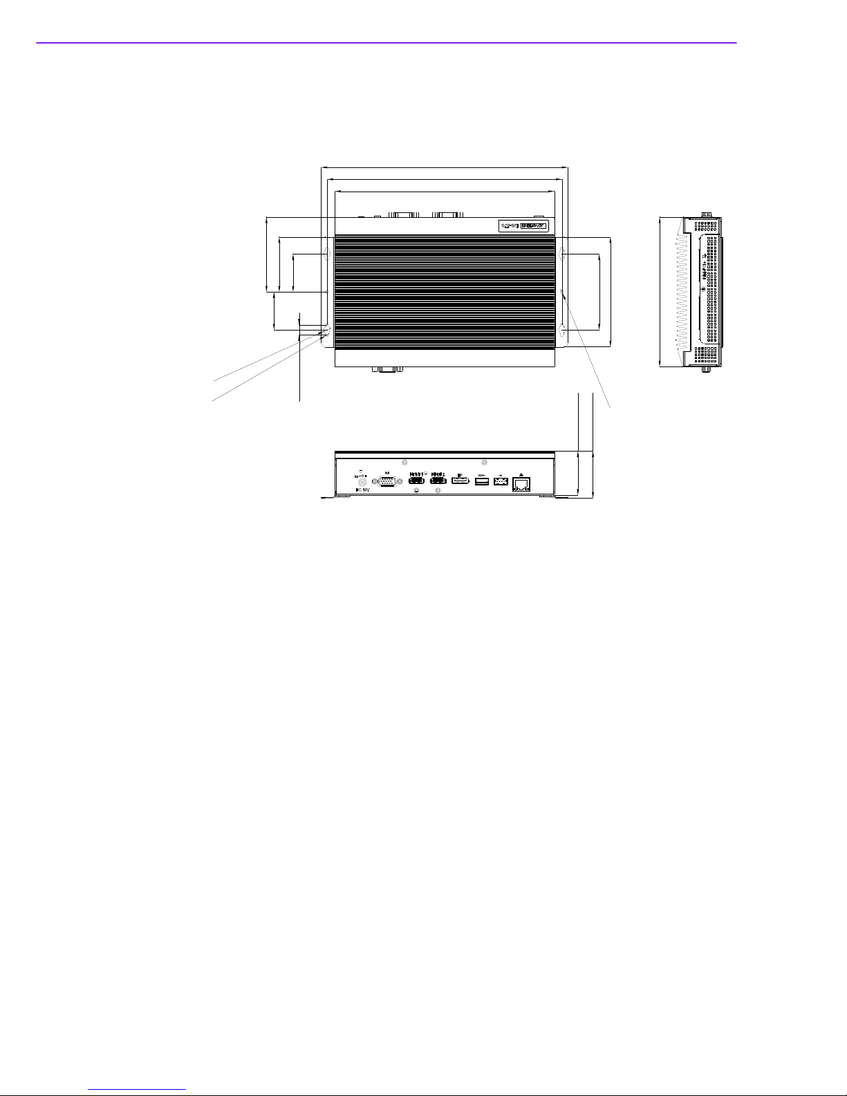
1.4 Mechanical Specifications
Dimensions: 220.0 x 150.0 x 44.2 mm (8.67" x 5.91" x 1.74") (L x W x H)
Figure 1.1 DS-570 Mechanical Dimensions
Weight: 1.7 kg (3.75 lb)
1.5 Power Requirements
System Power:
–Minimum power input: 19 VDC, 3.42 A
RTC Battery: 3 V/195 mAH BR2032
1.6 Environment Specifications
Operating Temperature: 0° C ~ 40° C (32 ~ 104° F) / 0° C~ 70° C (32 ~ 158°
F) with extended temperature RAM and SSD
Relative Humidity: 95% @ 40° C (non-condensing)
Storage Temperature: -20 ~ 70° C (-4 ~ 167° F)
Vibration Loading During Operation: 1.0 Grms, IEC 60068-2-64, random, 5 ~
500 Hz, 1 Oct./min, 1 hr/axis.
Shock During Operation: 20 G, IEC 60068-2-27, half sine, 11 ms duration
Safety: UL,BSMI, CCC, CB, LVD
EMC: CE, FCC Class B, BSMI
220 [8.661]
235.40 [9.268]
247.40 [9.740]
38 [1.496]
38 [1.496]
76 [2.992]
110 [4.331]
Ø3.50 [Ø0.138]
55 [2.165]
75 [2.953]
Ø7 [Ø0.276]
Ø3.50 [Ø0.138]
10 [0.394]
44.20 [1.740]
47.20 [1.858]
150 [5.906]

Chapter 2
2Hardware Installation
This chapter introduces DS-570
external I/O and the Hardware
installation.
DS-570 User Manual 6
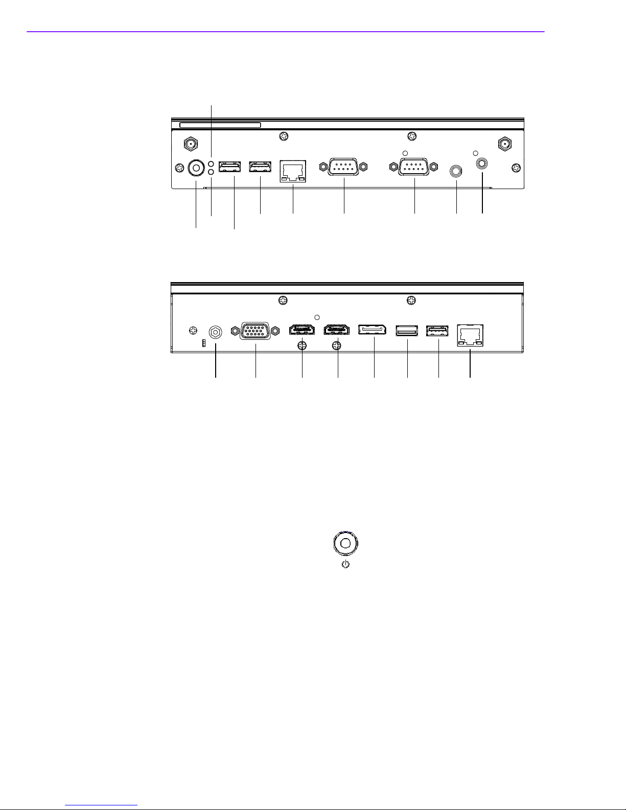
2.1 DS-570 Front and Rear Views
Figure 2.1 Front view
Figure 2.2 Rear view
2.2 DS-570 Front External I/O Connectors
2.2.1 Power ON/OFF Button
DS-570 has a power ON/OFF button on front side. Push this button to turn the sys-
tem ON and OFF. It can also support 4 second delay soft power off.
Figure 2.3 Power button
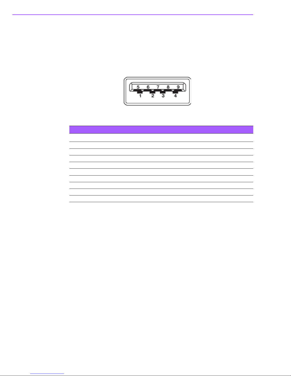
2.2.2 USB Connectors
DS-570 front side provides 2 USB 2.0 interface connectors, which give complete
Plug & Play and hot swapping capability for up to 127 external devices. The two USB
2.0 interface are compliant with USB UHCI, Rev. 2.0. The USB ports support Plug
and Play, which enables you to connect or disconnect a device without turning off the
computer.
S/PDIFMic. inCOM 1COM 2GLAN 1
USB 3
2
S/PDIFMic. inCOM 1COM 2GLAN 1
USB 3
USB 2
Power sw.
HDD LED
WiFi LED
DC IN VGA HDMI 1 HDMI 2 DP++ USB 3.0 USB 1 GLAN 2

7 DS-570 User Manual
Chapter 2 Hardware Installation
Figure 2.4 USB connector
2.2.3 Ethernet Connector (LAN)
DS-570 provides two RJ45 LAN interface connectors (1 x LAN in front-side; 1 x LAN
in rear-side), they are fully compliant with IEEE 802.3u 10/100/1000 Base-T CSMA/
CD standards. The Ethernet port provides a standard RJ-45 jack connector with LED
indicators on the front side to show its Active/Link status and speed status.
Figure 2.5 LAN connector
Table 2.1: USB Port Pin Assignments
Pin Signal Name
1VCC
2 USB Data-
3 USB Data+
4GND
Table 2.2: LAN Connector Pin Assignments
Pin Signal Name
1MDI0+
2MDI0-
3MDI1+
4MDI1-
5GND
6GND
7MDI2+
8MDI2-
9 M D I 3 +
10 MDI3-
11 VCC
12 ACT
1 3 L i n k 1 0 0 #
14 Link1000#

DS-570 User Manual 8
2.2.4 COM Connector
DS-570 provides two D-sub 9-pin connectors serial communication interface port.
The port can support RS-232 mode communication.
Figure 2.6 COM connector
2.2.5 Audio Connector
Microphone can be connected to the audio jack (only supports mic in function).
Figure 2.7 Audio connector
2.2.6 S/PDIF Connector
The S/PDIF port allows you to transfer digital sound to an amplifier or television. It
supports jack-sensing and can be the Line out function.
Figure 2.8 S/PDIF connector
2.3 DS-570 Rear External I/O Connectors
2.3.1 Power Input Connector
DS-570 comes with a DC-Jack header that takes 19 VDC external power input.
Table 2.3: COM Port Pin Assignments
Pin Signal Name
1DCD
2RxD
3TxD
4DTR
5GND
6DSR
7RTS
8CTS
9RI

9 DS-570 User Manual
Chapter 2 Hardware Installation
Figure 2.9 DC input connector
2.3.2 VGA Connector
DS-570 provides one high resolution VGA interface connected by a D-sub 15-pin
connector to support VGA(CRT) compatible monitors. It supports display resolutions
of up to 2048 x 1536 @ 60 Hz.
Figure 2.10 VGA Connector
2.3.3 HDMI Connector
DS-570 2 HDMI (High-Definition Multimedia Interface) connectors provide all-digital
audio/video interface to transmit the uncompressed audio/video signals and are
HDCP and (only one of them, HDMI 1, can support). Connect the HDMI audio/video
device to this port. HDMI technology can support a maximum resolution of 3840 x
2160p but the actual resolutions supported depend on the monitor being used.
Table 2.4: VGA Connector Pin Assignments
Pin Signal Name
1RED
2GREEN
3BLUE
4NC
5GND
6GND
7GND
8GND
9NC
10 GND
11 NC
12 DDC DAT
13 H-SYNC
14 V-SYNC
15 DDC CLK

DS-570 User Manual 10
Figure 2.11 HDMI connector
Table 2.5: HDMI Connector Pin Assignments
Pin Signal Name
1TMDSData2+
2GND
3TMDSData2–
4TMDSData1+
5GND
6TMDSData1–
7TMDSData0+
8GND
9TMDSData0–
10 TMDS Clock+
11 GND
12 TMDS Clock–
13 NC
14 NC
15 SCL
16 SDA
17 GND
18 +5 V Power
19 Detect

11 DS-570 User Manual
Chapter 2 Hardware Installation
2.3.4 DP++ Connector
DS-570 DP++ connector not only supports DP output but also can direct output sin-
gle-link HDMI and DVI signals using a simple passive adapter. It can support a maxi-
mum resolution of 3840 x 2160p but the actual resolutions supported depend on the
monitor being used.
Figure 2.12 DP++ connector
Table 2.6: DP++ Connector Pin Assignments
Pin Signal Name
1 ML_Lane 0 (p)
2GND
3 ML_Lane 0 (n)
4 ML_Lane 1 (p)
5GND
6 ML_Lane 1 (n)
7 ML_Lane 2 (p)
8GND
9 ML_Lane 2 (n)
10 ML_Lane 3 (p)
11 GND
12 ML_Lane 3 (n)
13 CONFIG1
14 CONFIG2
15 AUX CH (p)
16 GND
17 AUX CH (n)
18 Hot Plug
19 Return
20 DP_PWR
DS-570 User Manual 12
2.3.5 USB Connectors
DS-570 rear side has 2 x USB interface connectors (1 x USB 2.0 and 1 x USB 3.0),
which give complete Plug & Play and hot swapping capability for up to 127 external
devices. The three USB 2.0 interface are compliant with USB UHCI, Rev. 2.0. and
the USB 3.0 is compliant with USB UHCI, Rev. 3.0. All the USB ports support Plug
and Play, which enables you to connect or disconnect a device without turning off the
computer. USB 2.0 pin definition refer Table 2.1
Figure 2.13 USB 3.0 connector
Table 2.7: USB 3.0 Connector Pin Assignments
Pin Signal Name
1 VBUS
2 USB Data-
3 USB Data+
4GND
5StdA_SSRX-
6StdA_SSRX+
7 GND_DRAIN
8StdA_SSTX-
9StdA_SSTX+
Other manuals for DS-570
1
Table of contents
Other Advantech Digital Signage manuals

Advantech
Advantech DSA-2102SAE User manual

Advantech
Advantech DS-780 User manual

Advantech
Advantech ARK-DS762 User manual

Advantech
Advantech DS-370 User manual

Advantech
Advantech UBC-DS31 User manual

Advantech
Advantech DS-080 series User manual

Advantech
Advantech DS-862 Series User manual

Advantech
Advantech DSD-5038 Series User manual

Advantech
Advantech UBC-DS31 User manual

Advantech
Advantech DSA-3400 User manual


