Fortress Technologies ALARM COMBO SYSTEM FS-50 System manual

FS-50 Alarm Combo System
INSTALLATIONHANDBOOK:
INTRODUCTION
Congratulationson yourchoiceofaCrimestopper combination alarm&remoteengine starter withDataPort
Technology
Thisinstallationbookisdesignedfortheinstallerorindividualwithanexistingunderstandingof
automotive electricalsystems,along withtheabilitytotestandconnectwires forproperoperation.Toease
installation,wesuggest thatyouREAD THISMANUALbeforebeginningyourinstallation.Thisbookis
providedasaGENERALGUIDELINEandtheinformationcontainedhereinmaydifferfromyourvehicle.
DISCLAIMER:
CrimestopperSecurity Products,Inc.anditsvendorsshallnotbeliableforanyaccidentresultingfromthe
useofthisproduct.Thissystemisdesignedtobeprofessionallyinstalledintoavehicleinwhichall
systemsandassociatedcomponentsareinperfect workingcondition.
TECHNICALSUPPORT(800)-998-6880
Monday-Friday8:00am-4:30pmPacificTime
Website: www.crimestopper.com
CRIMESTOPPERSECURITYPRODUCTS, INC.
1770S. TAPO STREET
SIMI VALLEY, CA.93063
REV 12.2008
Thisdevice complies withFCC Rules part 15. Operationis
subject to thefollowingtwo conditions: 1) Thisdevice may not
causeinterference, and(2) thisdevice must acceptany
interference thatmay be received, includinginterference that
may cause undesired operation.The manufacturer isnot
responsiblefor anyradioor TV interferencecausedby
unauthorized modificationto thisequipment. Such
modificationcouldvoidtheuser'sauthority to operate the
equipment.

2
TABLEOF CONTENTS
Cautions&WarningsandComponentMounting..…..………………………………………………………………………3
Antenna Diagram…….………….…………………………....……………...……………………………………………..……4
Wiring Information….……….…………………………....……………...……………………………………………..……5-11
Shock Sensor …….………….…………………………....……………...……………………………………………..……12
PowerDoor LockWiring, Systems&Diagrams.........……………...….………..…….……..…………...……………13-15
Tachless, TachReference,TachFinder, TimedCrankModes………..……………………………………………....16-18
DieselGlowPlug Delay………………………………………………………………………………………………...………19
ProgrammableOptions, OptionsReset……….………………………………………………….………….………...…19-25
RemoteTransmitter/ TransceiverProgramming…………………………………......…..…………………...…...…...….26
2-VehicleOperation……………………………………………………………………………………………………...……..27
AlarmTrigger Diagnostics…………………....…………………………………………………………………….………….28
RemoteStart Diagnostics………….……………………..………………………………………...…………………...…….28
JumperPinDiagram…………………………………………………………………………………………………………....29
SystemWiring Diagram, DATAPort Diagram..…………………………………………………………….……………30-32
PR PRE-INSTALLATIONCONSIDERATIONS
BEFORE BEGINNING,check all vehiclemanufacturer cautionsandwarnings regardingelectricalservice (AIR BAGS, ABS
BRAKES, ENGINE/ BODYCOMPUTER AND BATTERY).
PLANOUTYOUR INSTALLATION.Youshouldpre-determinethelocationofthe ControlModule(Brain),Valet button,
LED, and Sirenlocations. This willsave time and ease theinstallationprocess.
USE VOLT/OHM METER totest andlocate all connections. Test Lights or LightedProbes couldpossiblydamage a
vehicle’s computersystem or cause anairbag to deploy.
ADDITIONAL PARTS, that are not included withthis unit, may beneededfor yourparticular vehicle. These items may
include extra relays, Door Lock Interface Modules, or Transponder Override modules.

3
CAUTIONS&WARNINGS
DAMAGERESULTINGFROMIMPROPERINSTALLATIONISNOTCOVEREDUNDERWARRANTY!!
DONOT remotestartyour vehicleinaclosedgarage.Makesurethatthe garage door isopen or there isadequate
ventilation. Failuretoobservethisrulecouldresult ininjuryordeathfrompoisonousCarbonMonoxidefumes.
DONOTROUTEANYWIRINGTHATMAYBECOMEENTANGLED withthe brake/gaspedals,steeringcolumn,or
anyother movingpartsinthe vehicle.
REMOVE MAINSYSTEMFUSE(S) beforejump-startingthevehicleorcharging thebatteryathighboost.DAMAGE
MAYOCCURTO SYSTEMIFPROPERPRECAUTIONSARENOTOBSERVED.
DONOT exceedtheratedoutputcurrentofanycircuiton theRemotestartmodule.Failure toobservethiswarning
will result indamagetotheunit. Output currentsarelisted where applicablethroughoutthismanual.
DONOT extend theRemotestartignition harness length.Mountthe modulesothatmainharnessreachesall
ignitionswitchwiring. Extendingthesewirescouldresult inpoor performance.
COMPONENT MOUNTING
CONTROLMODULE: The alarmcontrolmoduleshouldbemounted inaconcealed location. DONOTmountthe
controlunitintheenginecompartment. Fasten the moduletoabracketor wireharness usingthecableties
provided.
SIRENMOUNTING: Mountthesirenunderthehoodtofender-well orotherbodysurfacewiththeopenendfacing
downward.Run theredsirenwire through the firewall using arubber grommet. Ground the blackwire tothe body
metalnearthesiren.
LED: MounttheBlueLEDinavisiblelocation on thedashboard orconsole.
SHOCK SENSOR: Mounttheincludedshocksensor withwiretiestoanunderdashwire harness orfastenwith
screwstofirewall or side paneling.
OVERRIDE/PROGRAM/VALETBUTTON: MounttheOverride/Programpush-button inahidden butaccessible
location.Thisbutton isrequiredfor emergencydisarm,programming,andvalet mode.

4
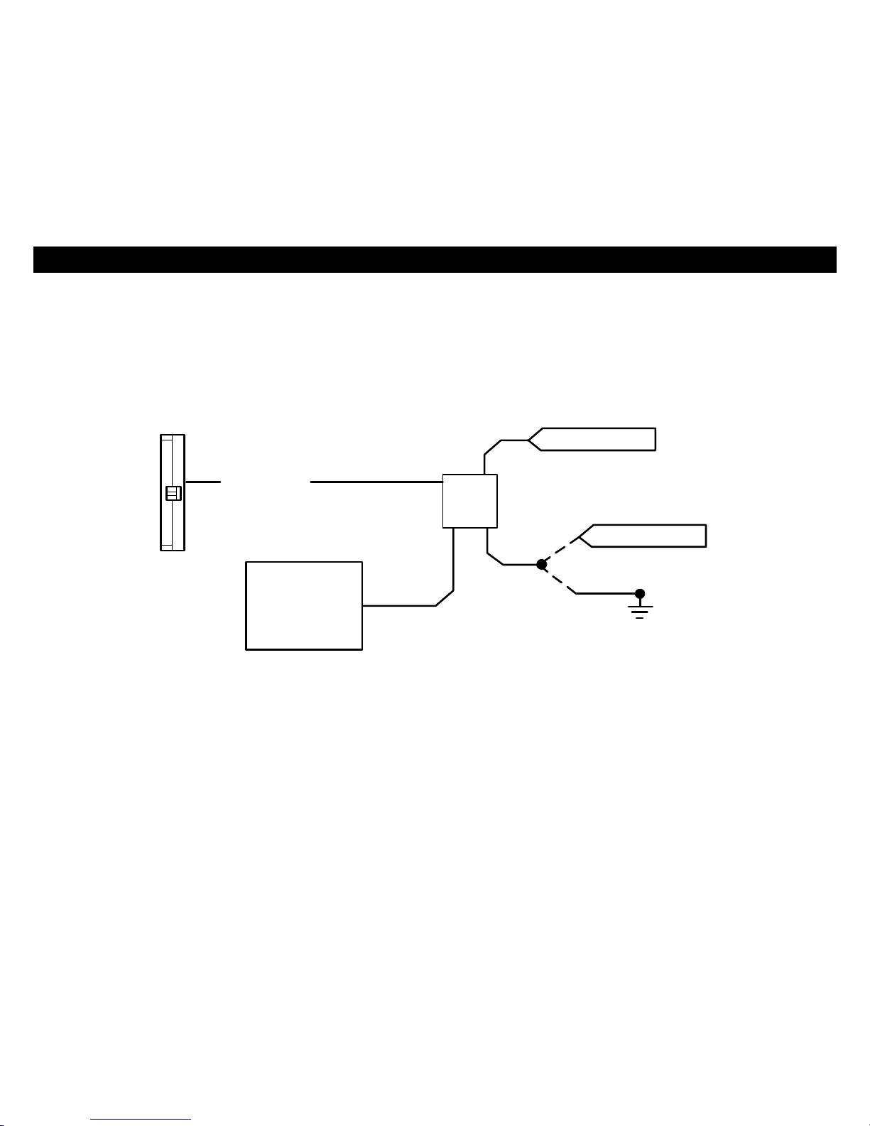
ANTENNADIAGRAM
ANTENNAMODULE: For optimumrange andperformance,the antenna/receiver moduleshouldbe located high up
on thefrontwindshieldglass.Forexample:behindtherearviewmirror. Note:Windowtintsor Filmsmaydecrease
the rangeofthesystem. Themounting surfaceforthe antenna shouldbe cleanand dry.
WINDSHIELD
ANTENNA
LOCATIONS

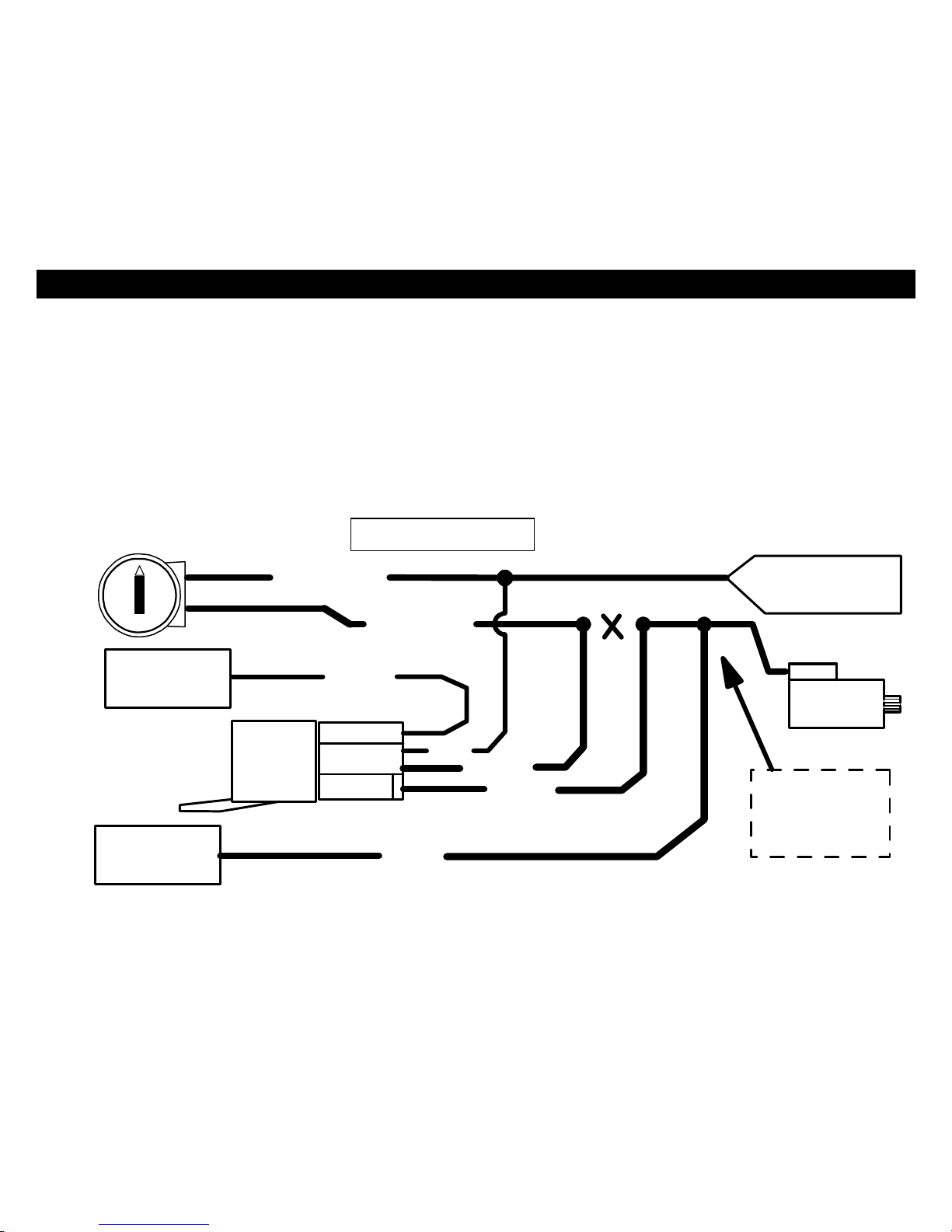
5
Momentary
Switch
GREEN
Optional TurboTimerWiring
(Notincluded)
WIRING:9-PINConnector
Green:MODEA:(-)StartActivationInput
Thiswireallowsanoutsidesourceoraccessoryto
activateaRemoteStart. A1-second Ground pulse
on thiswirewill trigger aremotestart.Thiswire
can be usedwithanRS-400temperature module.
Green:MODEB(-) OptionalTurboTimerInput
(3 Modes,Option #30) Thiswireallowsthe system
tokeep avehiclerunningfor1-5 minutes
[selectively]after removingthekey.Thismode
requiresthe useofamomentaryswitchthatisnotincludedwiththekit. Connecta2-polemomentaryswitchwith
one sidetochassisGroundand theother sidetotheGreeninputwire.If youownaturboorturbodieselvehicle,
youcannowallowthe systemtokeep your engine runningfor1-5minutesafter exiting/locking your vehicletocool-
downwithouttheneedfor an external“TurboTimer”.Seeoperator’smanualfor more information.
Brown:(+)SirenOutput
Connectbrownwiretosirenredwire. Connectblackwireofsiren tochassisground(bodymetal).
Brown/White:(-) 500mAHornHonkOutput(Optional,mayrequirearelay)
Connecttothe NegativeHorn Triggerwireusuallylocated near thesteering column.If the vehiclehorncircuit
requires+12V,arelayisrequired.RELAY WIRING: ConnecttheBrown/Whitewire toterminal85,connectrelay
terminals86 and 87 to+12Vconstantpower.Connectterminal30 ofthe relaytothe +12Vpositivedevice/circuitto
be activated.
Black/White:(-)500mADomeLightIlluminationOutput(Optional,Requires relay)
NegativeDomeLightSystem: Connectstoterminal85ofarelay.Connectterminal86to+12VConstant.
Connectterminal87 toChassisGround. Connect Terminal30totheNegativedomelightactivationcircuit.
PositiveDomeLightSystem: Connectstoterminal85ofarelay.Connectterminals86&87 to+12VConstant.
Connectterminal30 tothe Positivedomelightactivationcircuit.
6
WIRING:9-PINConnectorCont.
Green/Red:(-)500mARemoteAux.Output1(ProgrammableOption#10,requiresrelay)
Thisisaprogrammableoutputthatcanoperatetwodifferentways:1-(DEFAULT)DisarmwithRemoteAuxiliary
Outputthatprovidesa½second (-)Negativepulsewhen Button#3ispressed toopen aFactorypower trunkor
hatchrelease.2-RemoteAuxiliaryOutputwithoutdisarm
GREEN/RED 85 86
30 87
TrunkSoleniod
DomeLight
NEGATIVEAUXILARY OUTPUT
OR*
+12V CONSTANT
+12V CONSTANT
-OR-
AuxFunction
*Testactivationcircuit invehicle.
Connect to+12VforPositivecircuits
orGround forNegativecircuits.Relay
notincluded.
(-) AUXOUTPUT
OR
-OR-
Blue/Black:(-) 500mAIGNITIONOUTorREMOTEAUX. Output#2 (ProgrammableOption#17)
ThiswirefunctionsasaNegativeIGNITIONOUTPUT(GroundwhileRemoteStarting) for usewhenconnecting
factorySecurityBypass modulesorwhen an additionalexternalIgnitionRelayisrequiredforyour installation.This
wire can be programmed tofunction asanAUXILIARYOUTPUT#2providing amomentary(-)Negativeoutput
when Button #5 then#1ispressed and heldformore than 2seconds.TheAuxChannel#2 outputstaysonaslong
athebutton ishelddown. Connecttothe Negativeactivationcircuitofanauxiliarymoduleordevice.
7
WIRING:9-PINConnectorCont.
Blue/White:(-) PassengerDoorUnlock Output(Optional, requiresrelay)
Thiswireactivateswhen the unlockbutton onthe remoteispressed asecondtimewithin15secondsupon
disarming.Thiswire isused fortheOptionalSeparateDriver’s/PassengerUnlockfeature.Connectstounlock
circuitforpassenger door or doors.SeeDOORLOCKWIRING for specialconfigurationoptions(pages13-15).
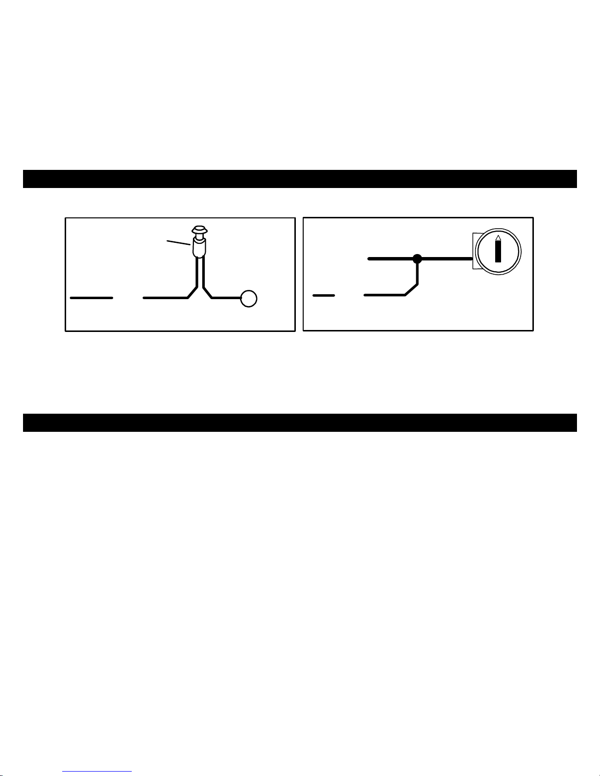
Orange:(-) NegativeStarterDisable/Anti-GrindOutput
ThiswireshouldbeconnectedtotheYellowwire ofthepre-wiredrelaysocketfor thestarter disable.Connectthe
blue wire ofthe relaysockettotheIgnition switched wireon the vehicle.Cutthe vehiclestarter wire and connect
eachhalftoanOrange wire ontherelaysocket. Thisoutputalsoturnsonwithremotestarttofunction asan “Anti
Grind” wiretopreventthe starter fromgrinding ifyougetinyour carandturnthe keytoofar afteritwasremote
started. Seestarter disablediagramonnextpage.
CUT
STARTERWIRE
STARTER
ORANGE
ORANGE
CONNECTTO
PRE-WIRED
OF ALARM
IGN.SWITCHED
BLUE
YELLOW
ORANGEWIRE
STARTERDISABLE
RELAY&SOCKET
IGNITIONSWITCHED
"ON"&HOT THROUGH
CRANKING
BROWN
STARTOUTPUT
6-PINHARNESS
FROMALARM
MAKECERTAINTO
CONNECT BROWN
WIRETO STARTER
MOTORSIDE!!!
STARTERDISABLE:

8
WIRING:9-PINConnectorCont.
Orange/Black:(-) OEMDisarm Output
ThiswireprovidesaGroundpulsetodisarmthe vehiclesFactoryAnti-TheftSystempriortoaRemoteStart.
Connectthiswire tothe vehicles' anti-theft disarmwire.Thiswire issometimesfound coming offthe Driver's door
keyswitchor at the FactoryAnti-theftcontrolmodule.
WIRING:3-PINConnector
White/Red:TachometerInput
When installingthissysteminTACH REFERENCEmode,thiswiremustbeconnectedtoavalidsourceofAC
voltage.Thiswire allowsthe unittosensetheengine running.See TachSectionon Page16-18 for more
information.
Black:ChassisGround
Connecttobodymetalofthevehicleusing asheetmetalscrewand astar washertoensureagood ground.Keep
the Groundwire short. Scrape awaypaintor debrisfromgroundlocation.
WHITE:10Amps+12Voltsor(-)500mANEGATIVE PARKINGLIGHTOUTPUT:
Connecttovehicleparking lightcircuitatthebackoflightswitchorifthisisnotpossible,connectdirectlytooneof
the parking lightsatthefrontofthe vehicle.Ifyour vehiclehasamultiplexlighting systemthatrequiresa(-)
Negativeparking lightoutput, thenmovethe jumperfrom(+)to(-).SeeJumperPinDiagram(Pg.29).Some
European vehiclesrequireseparateleftandrightcircuits. Useadualrelayor diodestoisolatetheoutput.
NOTES:(1)Defaultparking lightoutputis+12 volts.(2)Use anexternalrelay forvehicles that drawexcess
currentfromextrarunninglights, lightbars, ortrailers.Parkinglightoutputislimitedto+10 or(-)0.5AMPS.
WIRING:6-PINHigh CurrentConnector
\
PIN1:BROWN:STARTEROUTPUT(30AMax.)
PIN2:GRAY: ACCESSORY(HEAT/AC)(30A)
PIN3:RED: +12VPOWERINPUT(BATTERY)FUSED(30A)
PIN4:RED: +12VPOWERINPUT(BATTERY)FUSED(30A)
PIN5:PINK: IGNITION1(30AMax.)
PIN6:PINK/WHITE:START2,IGN2,ACC 2OUTPUT(30Max.)
NOTE! Use
External Relays
for High Current Ignition
and/or Accessory circuits
greater than 30A.Failure to
do so could result in damage
to the unit that is notcovered
under warranty.

9
WIRING:5-PINConnector(TriggerInputs)
Violet:(+)DoorPinSwitchInput
SameastheGREENwire belowexcept thiswireisusedforvehiclesthat showapositivevoltage (+12volts)when
the door isopen andaground whendoorsareclosedasinmanyFord,Lincoln, andMercuryvehicles.
Green:(-)DoorPinSwitchInput
Identifythe wirethatreadsgroundwhen anydoorisopen and12 voltswhenall doorsareclosed.Somevehicles
mayhaveisolateddoor triggers.Inthiscaseyoumayneed torun additionalwiresfromotherdoorsor go directlyto
the wire thattriggersthe vehicle’sinterior domelight. Sometimesnewer vehiclescontainaseparatebodycontrol
module(BCM) wherethe doortriggercircuitcanbe located.MostvehicleswillNOTrequirethe useofBOTHGreen
andVioletdoortriggerwires.
Blue:(-) Hood/TrunkPinSwitchInput
Inputtrigger for agrounding hood or trunkpinswitch.Connecttoexistinghood andtrunkpinswitchesthatread
groundwhenopen.Ifno existing switchesare available,install newpinswitchesifdesired.Note:DONOTmount
newpinswitchesinwaterpathways.
Pink:(+12V)+/-DieselGlow PlugInputorPassive Carjack Input(ProgrammableInputWire)
+/-Trigger: See diagram(Pg.29)for JumperPinConfiguration.
+/-GlowPlugInput(Diesel Vehicles Only)
ConnectPinkwire toindicator circuitthatshowsa(- or+)Signalwhilethe“WAITTOSTARTLAMP”ison.
When thiswireisused, the systemwill wait until lightturnsoff beforeattemptingaremotestart.
Passive Carjack Trigger
When using Carjackprotection,connectthisPinkwire toa(+or -) toggleswitch,or+12Vignition source
dependingonyourlevelofCarjackprotection.When +12Visappliedtothiswire withtheIGNon, thenCarjack
isarmed.Ifadoor isopened then closed withignition on,the Carjackcountdownwill begin.See Diagram
Belowforwiringconfigurations.DONOTconnectthePinkCarjackwire toIgnitionunless thereisextreme
dangerofaCarjack.When using theIgnition,Carjackisarmed all thetimeand mustbereseteachtimea
doorisopenedandclosed.
10
WIRING:5-PINConnector
+
12 V
PINK
OPTIONALCAR JACK WIRING:
HIDDEN BUTTONor
TOGGLESWITCH
(NotIncluded)
IGNSW
+IGN
CONTROLLED W/SWITCH
PINK
FULL-TIMECARJACK
White:(+12V)BrakeReset
ConnecttheWhitewire tothe side ofbrakepedalswitchthat shows+12voltsONLYwhenpedalisdepressed.This
will turnoff the remotestartif someoneattemptstodrivethecarwithout thekeysorif the Ignitionkeyisnot turned
on all theway.
WIRING:2-PINLED/ 2-PINProgram-ValetButton (22 gaugewires)
MountLEDinavisiblelocationontheDashor Console. Connectthesmall 2-pinplugfromtheLEDtothe control
module.Note:Connectorsaredesigned sothattheywill onlyplugintotheirappropriateslots.
MounttheValet/Program/Override button inasuitablelocation. Connectthe2-pinplugfromtheSwitchtothe
controlmodule. Note:Connectorsaredesignedsothat theywill onlyplugintotheirappropriateslots.

11
WIRE:4PINOUTPUT CONNECTOR
YELLOW/BLACK:(-)OEMREARMOUTPUT
Thiswire providesaground pulsetorearmthevehicles'FACTORYanti-theftsystemafter atimed-outoraborted
remotestart. Connectthiswire tothe vehicles' anti-theft rearmwire or tothedoor pincircuitdepending onyour
requirements. Thiswiremaybeneededtopulsethe door pincircuit onvehicleswithretainedaccessorypower.
BLUE/ORANGE:(-)STARTER#3
Thiswireprovidesagroundoutput for vehiclethatrequiresathird starterwiretoremotestart.
BLUE/ORANGE
CONNECTTOIGN
85 86
+-
30 87 BATTERY
STARTER
VIOLET/WHITE:(-)AUX.3
The Violet/Whitewire foranegativeoutput foraMomentary, Pulse,Timed orLatched output, dependingonoption
used. Option#26 and27controlsthesefunctions.
GREEN/WHITE:(-)AUX.4
The Green/Whitewire foranegativeoutputforaMomentary,Pulse, Timed or Latchedoutput, dependingonoption
used. Option#28 and29controlsthesefunctions.
12
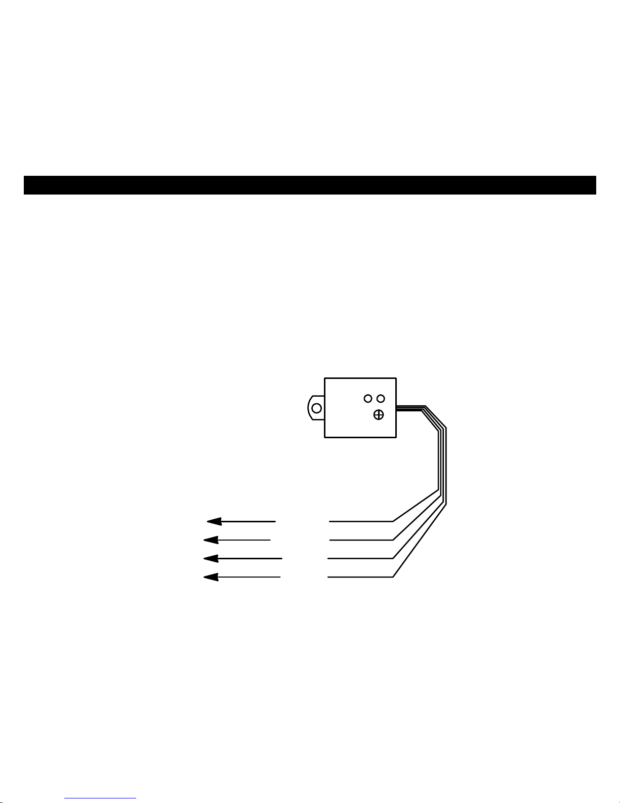
WIRING:4-PINShock Sensor(22 Gaugewires)
SHOCK SENSOR: Thesensorsupplied withthissystemdoesnotrequireanyadditionalwiring.Simplymountthe
sensorinasuitablelocation,plugitin,andadjustthesensitivity.Thereare2LED’sontheshocksensortoassist
youinadjustingsensitivity.TheGreen LEDindicatesthe“Warn Away”leveland theRedLEDindicatesafull alarm
shocksensorviolation.
Usethe adjustmentknobtosetthe sensitivityofthesensor.The adjustmentknob adjustsbothPre-Warn and alarm
trigger.
GREENLED REDLED
(-)PRE-WARN
(-)TRIGGER
GROUND
12VOLTS
YELLOW
ORANGE
BLACK
RED
(Trigger)
(Pre-Warn)
Adjustment
SHOCK SENSOR

13
CrimestopperDoorLock Accessories:
CS-6600DLM: Dual-relayplug-inmoduleforReverse
Polarity,Positive, orAftermarket Motors.
CS-6500DLI: Plug-inpulseinverterthat convertsthe
Negativeoutputsof the systemtoPositivetypeforPositive
DoorLock systems.
CS-610S1: Aftermarket doorlock actuator(motor).
POWERDOORLOCKS:WIRING&SYSTEMTYPES
PIN1:BLUE: (-)NegativepulseforUNLOCK
PIN2:RED: 12VWhen using externalrelays(TERM86)
PIN3:GREEN: (-)Negativepulsefor LOCK
DETERMININGDOORLOCK TYPE: Werecommend
determiningthe typeoflocking systemthe vehiclehas
beforeconnectinganywires.Incorrectconnection may
resultindamagetothe alarmand/orvehiclelocking system.
Doorlockinformation isprovidedasaguide. Yourvehiclemaybedifferent.
Negative Trigger(-):ManyImports;LatemodelFord&General Motors
Negativetrigger door locksystemssendaNegative(Ground)pulsetoexistingfactoryrelaystolockandunlockthe
vehicledoors.
Positive Trigger(+):ManyGeneral Motors;Chrysler/ Dodge/ Plymouth
Positivetriggerdoor locksystemssend aPositive(12V)pulsetoexisting factoryrelaystolockandunlockthe
vehicledoors.
Reverse Polarity:ManyFord/Lincoln/Mercury/Dodge/Chrysler/Plymouthandearly90’sGMTrucks
ReversePolaritysystemsusenorelays,butinstead the doorlock/unlockmotorsare controlleddirectlyfromthelock
and unlockswitchesinthedoor.The lockand unlockwiresrestatNegativeGroundwhen notinuse.When the
lockor unlockbutton ispressed,one ofthe circuitsis“Lifted”andreplacedwith+12Vcausing alockor unlockto
occur.
SingleWire(Dual Voltage):Latemodel Chrysler/Dodge/PlymouthVehicles, some2000-UPGM
DualVoltagesystemshavelock/unlock switchesthatsend varying levelsofPositivevoltage ORNegativeground
currenttotheSAMEwire forbothlockand unlock.When the vehicle’sBodyComputer Module(BCM) ordoor lock
modulesensesdifferentvoltageson thiswire,the systemwill either lockor unlock.Singlewire door locksystems
requirerelaysandresistors.
DatabusSystems2003-UPGMTrucks&SUV’s, ‘96-04JeepGrandCherokee
Databussystemssend lowcurrent“Datamessages”tothe doorlockcontrollersonanetworkinordertolockand
unlockthevehicle.Toinstall aftermarketsystemsinthesevehicles,aninterfacemoduleisrequiredthatconverts
the regular lock/unlockpulsesinto“Datamessages”toallowlocking &unlocking.Interfacemodulesaresold
separately.

14
DOORLOCK WIRING
AFTERMARKETMOTOR/DOORLOCKWIRING
REVERSE POLARITYDOORLOCKWIRING
GREEN
GREEN FUSED
FUSED RED
RED +12V
+12V BLUE
BLUE +
+
86858685
8685
8685 8787
8787 3087A3087A
3087A3087A
+L
CUT
UL
CUT
MASTER
SWITCH
NEGATIVETRIGGERDOORLOCKWIRING POSITIVETRIGGERDOORLOCK WIRING
GREEN
GREEN FUSED
RED +12VRED BLUE +
BLUE
86
858685 8787 3087A30
87A
FACTORY
FACTORY
LL
POWER
POWER LOCKING
LOCKING
UL UL
RELAYS RELAYS
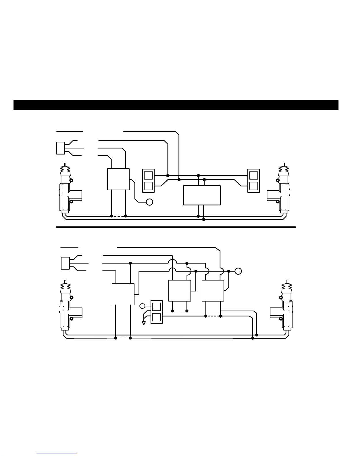
15
SEPARATEDRIVER’SDOORUNLOCK WIRING
NEGATIVE TRIGGERDOORLOCKS
BLUE/WHITE
GREEN
RED
BLUE
DRIVER'S
DOORMOTOR
8685 LL
87 ULUL
87A
30 FACTORY LOCK
RELAYS
+12V
+FUSED
UNLOCKWIRE CUT
WIRINGFORREVERSE POLARITYDOORLOCKS
BLUE/WHITE
GREEN FUSED
RED +12V
BLUE +
MASTER
86858685
SWITCH
8685 8787
87 30
87A
30
87A
30 87A
+
L
CUT
UL
CUT
CUT
UNLOCK WIRE
LOCKWIRE

16
TACHLESS MODE
YoursystemincludesaTach-lessmodethat activelymonitorsandcomparesthe vehicle’srestingvoltageversusits
runningvoltageeachtimearemotestartisperformed;[insteadofthe conventionaltach-pulsemethod]. Smart
Tachlessmodeadjustsautomaticallytomaintainoptimumefficiencyoverthelifeoftheinstallation.
IMPORTANTNOTES:
(1)SETUPmaybe required for the Tachless Mode.Ifyour vehiclehasNOTbeen atrestforaperiod oftime(Hot
engine),then youmustdrainthe surfacechargefromthe battery.Unplugmainpower harness fromsystem,turn
HEADLIGHTSONfor4minutestodrainoffexcess surfacecharge onvehicle’sbatterythenreconnect.
(2)Ontherare occasion thatTachless mode doesnotoperatesatisfactorily,changethevoltagereferencelevelas
describedbelow, oruseadifferent modesuchas“TachReference”mode,or “Timed Crank”mode.
TACHLESS ADJUSTMENT:
IntheeventTachless over-cranksorunder-cranksyour starter,thesettingscan be changed.The purposeof
adjusting the “SmartTachless”Mode istoraiseor lower thevoltage referencethresholdfromthe 93%defaultpoint.
Raisingor loweringthis93%pointshouldincreaseor decreaseyourcrankingtimerespectively.You canadjustthe
range from79%to100%inone percentincrements.Factorydefaultsetting [starting point] isinthe middleat93%
whichshouldworkfor mostvehicles.Ifyoufeelyou needtofine tune the Tachless mode,thenfollowthesteps
belowtoadjust itsreferencelevel.
1.Openhood(or groundthe Blue hood pinwireifno hood pinisinstalled)
2.Turn the keytotheONposition (donotstartvehicle).
3.Press programbutton5times,after afewsecondsthe unitwill flashthelights5times.
4.Carefullypresstheprogrambutton24 timestogettooption#24.You mustgetalightflashafter eachpress.If
the lightsdidn’t flash, thentheunitdidnotregisteryourbuttonpress. Onlycount thelight flash.
5.Press theLockButton#1 ontheremotetodecreaseby1%(lightswillflash1Xforeachpress);Press theUnlock
Button#2toincreaseby1%(lightswill flash2Xforeachpress); PresstheTrunkButton#3toreset to93%(lights
will flash3X).The unitwill stopproviding lightflasheswhen youreachthebottom(79%)orthetop(100%)ofthe
adjustmentrange.If youlost track, thenjustpress Button#3toresetbackto93%andbeginagain.
6.Turn Ignition OFF,Closehood(or un-ground theBluewire) andcheckoperation.

17
TACH MODE&TACH FINDERFEATURE
TachReferenceMode providesreliableremotestartingperformancethoughenginespeedsensing.When using
TachReferenceMode,theWHITE/REDwire isused for Tachsignal[EngineRPM]input. Mostmodernengines
includevariouspointswherethe Engine Speed[Tach]or A/Csignalmaybeobtained.TachSignalexamples:
Negative(-) sideofignitioncoil,atthe DistributororIgnition ControlModule,Coil Pack,EngineComputer,or
Crankshaft Sensor.SometimesFuelinjectionsolenoidsandAlternatorstatorpinscan beused.TheseTachSignal
locationsmentionedareprovidedasaguide,yourvehiclemaydiffer.Somelocationswill NOTbeagoodlocation
for TachsourceduetoRFnoiseor ComputerData.UsetheTACHFINDERfeatureif needed.
TACH FINDERFEATURE:
The TachFinder modecanassistyou inlocating orverifyingaTachsourcefor your installation.FollowtheTach
Finder stepsbelowtolocatesignal.The unitwill begintoflashthe parking lightsifyouhavetheWhite/Red wire
connected toavalidtachsource.Iflightsdonotflash,thentryanotherwireuntil youlocateatachsignalthatwill
causethe Parking lightstoflash.NOTE:Onvehiclesequippedwithdaytimerunning lights,itmaybedifficulttosee
anyflashingparking lights.Inthiscaseyouronlynotification will be the slight“ticking” soundcoming outofthe
modulefromtheon-board flashinglightrelay.
TACH FINDER:
1.Openhood(Groundthe Blue hood pinwire ifnohoodpinisinstalled)
2.Start Engine withthe key.(Pinkignitionwire must beconnected)
3.Press theProgrambuttonfor2seconds
4.Lightswill beginflashing iftheWhite/Red wire isconnectedtoavalidtach
5.OnceTachislocatedthenturnoffengine andclosehoodtoabort.
6.See TachReferenceprogramming below.
TACH PROGRAMMING:
1.Openhood(GroundBluehoodpinwire if nohoodpinisinstalled).
2.ConnectWHITE/REDwiretoavalidTachsource.
3.Startenginewiththekey(Pinkignitionwire must beconnected).
4.Press programbutton5times,then wait for5lightflashes.
5.Wait at leastonesecondthenpushprogrambutton again(1)time,youshouldgetalight flashwiththebutton
press. Thisunit isnowatoption #1 forTachLearning.
6.Press the#1LockButtononremotetransmittertoprogramTach. NOTE: Pressing the BrakePedalalso
programsTach. OneLight Flash=TachMode.TwoLightFlashes=Tachless Mode.
7.Iflightsdonotflashforconfirmation, then tryanothertachsourceortrythetachfinderfeatureabove.

18
TIMEDCRANK MODE
Asan alternativetoTachor Tachless mode,“Timed Crank”providesan additionalmethod ofstarting the vehicle
withoutlocatinganexacttachwire.Itusesatimed cranking outputcombinedwiththe useoftheRed/Whitetach
wire asan engine ON/OFF monitor.The Red/WhiteTachwire MUSTSTILL beused withthismode.THIS
FEATUREMUSTBEPROGRAMMEDBEFOREUSE!THEREARE2LEVELSofprogrammingrequired:First, set
the systemfor“Timed Crank”operation,and secondlyyoumayneed toadjusttheamountofcranking time.There
are4different cranktimesavailablefor use.SEE OPTIONPROGRAMMINGCHARTFORSETTINGS.
HOWTO USE THISFEATURE:
1.Gotothe“ProgrammableOptions”section,andset Option#16 to“Pre-Set".(Itisnormallyset to“TachMonitor”)
2.With“Pre-Set”Cranking timeturned ON,youwill STILL havetoconnectthe Red/WhiteTachwiretoatach
sourceontheengine.TheRed/WhiteTachwirebecomesasimple“EngineMonitor”.Although theunitwill not
be using the Red/Whitewiretostartthemotor,itwill beusing thiswiretodetermine whetherthemotor isrunning
or not.Thisisamandatoryconnection.A“crude”or“less exact”tachsourcecanbe usedonlywhen in“Time
Crank”mode.
3.Usingthevehiclekey,starttheenginetogeta“feel”ofhowlongthecranking time is.Oncethe“Timed Crank”
mode isturnedon,thedefaultcrankingtimeissettoaDefaultof0.50seconds.Werecommendbeginningwith
thissetting. Tryaremotestart and seeif thecrankingisappropriatefor yourvehicle
4.If0.50secondsisnotanappropriatestartercranking time,thengotoProgramming Option#21andchangethe
cranktimesetting toalongervalue. Thevaluesareasfollows:0.5, 0.75. 1.0,and1.5seconds.
WARNING:Thismethodofstartingthevehicleisnotas reliableasusing regular“Tach”or“Ultra-Smart”
Tachlessmodes.Thismethodshouldbeusedonlyintheeventthatatachwirecannotbelocatedusingthe
normaltachprogrammingandtachfinder.Whenusingthismethod,theremaybecertainoperating
anomalies requiring seasonaladjustments. These are,butnotlimitedto:
•Startermayunder-crankinextremecoldweather.Vehiclemaynotstarton1st attemptandmayrequirea
2nd try,3rd try,ormaynotstartatall ifunsuccessfulafter3attempts.
•Inwarm weatherwhenyourvehiclemaystartveryquickly,“TimedCrank”modemaytendtoover-crank
thestarter.
•Theonlywaytopossiblycorrect theabove issues istogo totheOption #21and adjustthecranking
time.Whenin“TimedCrank”mode,thecrankingtimecanonlybeadjustedmanuallythrough option
#21. Whenusing Ultra-SmartTachless orRegularTachmodes,crankingtimeisadjustedautomatically.

19
DIESEL GLOW PLUGDELAY
Thisfeatureprovidesasolution for dieselvehicleswithouthavingtoconnecttothe GlowPlug-“WaittoStartCircuit”
input.Thismaybe due toavarietyofreasonsforexample:If your vehicledoesnothaveaviable“WaittoStart
Circuit”or youcannotlocateandidentifythecircuit. You canchoosefromaselection of“pre-cranking” delaytimes.
Oncethismode isactivated,thesystemwill NOLONGERmonitorthe PINKglowplug inputwireandwill usea
delaysettingchosenbytheinstaller inthe option chart.
NOTES:ThisfeatureisOFFbydefaultand mustbe programmed before use.Oncethisfeature isturnedON,the
PinkGlowpluginputwire isnotused.The Remotestartunitwill alwayswaitthe programmed timebefore cranking
EVENIFtheglowplugswarmup first.Thereare3differentDelaytimesavailablefor use:10,20,or30seconds.
SEE PROGRAMMING OPTIONCHART, nextsection.
HOWTO USE THISFEATURE:
1.See the “ProgrammableOptions”nextsectionandchangeOption#22from"MonitorGlowPlugLight"toone of
the delayedtimevalues.(Defaultsettingistoalwaysmonitorthe PINKGlowPlug inputwire.)
2.Oncethisoptionhaschangedthe system will wait for the selectedtimebeforecrankingtheengine.
PROGRAMMABLEOPTIONS
You canprogrammultipleoptionsinonesessionifyoustart withthe lowestoption andcontinueontohigheroptions
[ifneeded]withoutrepeating steps#1-3 below.For example,youcanfollowthe programmingstepstochange
Option#2to“OFF”bypressingthelockbuttonontheremote,then youcancontinuepressing theprogrambutton
additionaltimestogettoahighnumberoption and change the settingwithouthavingtorepeatSteps1-5.Youcan
onlygo fromlowtohigheroption numbersinone session.
To EngageOption Programming:
1.OpenHood(groundblue hood pinwire if no hood pinswitchisinstalled)
2.Turn KeytotheONposition
3.Press program/ valetbutton5times,after afewsecondstheunitwill flashthelights5times.
4.Pushthe valet/programbutton[again] the numberof timesthat correspondstothe optionnumberdesired(1thru
30). Youmustget alightflashaftereachbutton press. See charton next pageforoptionlist.
5.When youreachthe desiredprogramming level, Pressbutton#1,#2 #3 or#4tochange the option.
6.Turn Ignition OFF,Closehood(or ungroundblue hood pinwire)and checkfor changedfeatures. Changeeach
optionindividuallyrepeating#1-5.

20
OPTIONPROGRAMMINGTABLE
Option
#OptionDescription TXButton#1 TXButton#2 TXButton#3 TXButton#4
1 EngineMonitoring LearnTach *Tachless*
2 Autolock withIgnition OFF *ON*
3 PassiveArming
WithIgnitionorLastDoor Ignitionandlastdoor
ON *OFF* Ignitiononly LastDooronly
4 ActiveRe-Arm ON *OFF*
5 PassiveLocks ON *OFF*
6 ParkingLightsonw/Disarm OFF *ON*
7 DataPortProtocol
OFASeries orSLSeries OFASeries *SLSeries*
8
RemoteStart&AuxiliaryOutput
Button Press Selection DoubleButtonPress *½SecondPress* Press andHold
9 SirenChirpsonRemoteStart OFF *ON*
10 Disarm onTrunkpop OFF *ON*
11 OpenDoorWarning 5Sec. *60 Sec.*
12 DoorLock Pulse Time 3 Sec. *0.5Sec.*
13 DoubleUnlock Pulse 2 Pulses *1Pulse*
14 Lock AfterRemote
Start/Abort OFF *ON*
15 Manual TransmissionMode ON *OFF*
16 TimedCrankorTachMonitor Pre-Set *TachMonitor*
17 Blue/Black WireFunction AUX#2 *(-) Run / Ignition*
18 SirenChirpswithArm/Disarm
OFF *ON*
19 “Wake Up"pulse onUnlock
(1-sec. +12VtoIGN) ON *OFF*
Table of contents
Other Fortress Technologies Car Alarm manuals

Popular Car Alarm manuals by other brands


Prestige
Prestige Prestige APS-20B installation instructions

CYCLOPS
CYCLOPS PARALYSER 165 User instructions

Black Widow
Black Widow BW-2000 CLASSIC installation manual

Hornet
Hornet 742T installation guide

Audiovox
Audiovox Rampage AA-939 installation guide

Directed Electronics
Directed Electronics AdvantGuard 5 owner's guide