FPG INLINE GN Series User manual

Inline GN Series
Refrigerated Well
IN-GNC08

Part No.23747 Rev. F June 2017 - 2 - Refrigerated Well GN Series
Copyright © June 2017 Future Products Group Limited.
All rights reserved.
No part of this publication may be reproduced, stored in a retrieval
system, or transmitted in any form or by any means, electronic,
mechanical, photocopying, recording or otherwise, without the prior
written permission of Future Products Group Ltd.
Cover picture
The picture shows the GN Refrigerated Well, mounted in a custom FPG
designed, mobile chassis assembly.

IN-GNC08 - 3 - © Future Products Group
Table of Contents
INTRODUCTION .................................................................................................................7
Welcome........................................................................................................................................................... 7
Future Products Group (FPG).................................................................................................................... 7
Guidance and Help..................................................................................................................................... 7
Warranty ........................................................................................................................................................... 7
Warranty Period.......................................................................................................................................... 7
Liability Exceptions..................................................................................................................................... 8
Specific Exclusions..................................................................................................................................... 8
Assessment................................................................................................................................................ 8
Time Limit................................................................................................................................................... 8
Caution ....................................................................................................................................................... 8
OPERATION .......................................................................................................................9
Configuration ................................................................................................................................................... 9
Mechanical Features.................................................................................................................................. 9
Food Display Options................................................................................................................................. 9
Operating Temperature.............................................................................................................................. 9
Condensate and Drain ............................................................................................................................... 9
Optional Lighting......................................................................................................................................... 9
Controls.......................................................................................................................................................... 10
Control Panel............................................................................................................................................ 10
Power Switch............................................................................................................................................ 10
Refrigeration Switch ................................................................................................................................. 10
Temperature Controller ............................................................................................................................ 10
Display Mode.................................................................................................................................................. 11
Choice of Mode ........................................................................................................................................ 11
Display Trays............................................................................................................................................ 11
Gastronorm Dishes................................................................................................................................... 11
Component Locations .............................................................................................................................. 11
Preparation..................................................................................................................................................... 12
Power Supply ........................................................................................................................................... 12
Turn on Refrigeration................................................................................................................................ 12
Pre-chilled Food ....................................................................................................................................... 12
Loading Restrictions................................................................................................................................. 12
Draughts................................................................................................................................................... 12
Defrost Cycle............................................................................................................................................ 12
Operating Routines ....................................................................................................................................... 13
Monitor Food Temperature....................................................................................................................... 13
After Hours ............................................................................................................................................... 13
Cleaning ................................................................................................................................................... 13
De-frost Cycle........................................................................................................................................... 13
Storage and Display Basics ......................................................................................................................... 14
Food Temperature.................................................................................................................................... 14
Display Time............................................................................................................................................. 14
Unsuitable Food Type .............................................................................................................................. 14
TROUBLE SHOOTING .....................................................................................................15

Part No.23747 Rev. F June 2017 - 4 - Refrigerated Well GN Series
CLEANING........................................................................................................................16
Cautions ......................................................................................................................................................... 16
Power ....................................................................................................................................................... 16
Water........................................................................................................................................................ 16
Exterior ........................................................................................................................................................... 16
Metal Surfaces.......................................................................................................................................... 16
Glass (Optional Hood).............................................................................................................................. 16
Louvers..................................................................................................................................................... 16
Interior............................................................................................................................................................. 17
Cabinet Well Layout ................................................................................................................................. 17
Deck Trays and Dishes ............................................................................................................................ 17
Air Louvers ............................................................................................................................................... 17
Side Grills ................................................................................................................................................. 17
Fan Cover................................................................................................................................................. 17
Stainless Steel Items................................................................................................................................ 18
Well Cleaning ........................................................................................................................................... 18
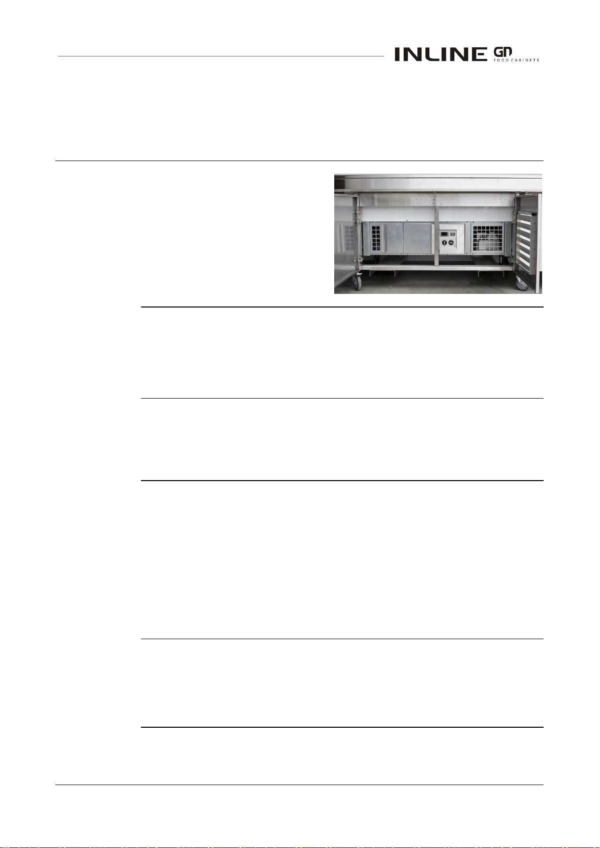
Cooling Coil .............................................................................................................................................. 18
Removal of Fan Deck............................................................................................................................... 19
Temperature Probes................................................................................................................................. 19
Cleaning Routines ......................................................................................................................................... 20
Schedules................................................................................................................................................. 20
Louvers..................................................................................................................................................... 20
Condenser Radiator ................................................................................................................................. 20
Inspection ................................................................................................................................................. 20
Correction................................................................................................................................................. 20
INSTALLATION ................................................................................................................21
Regulations .................................................................................................................................................... 21
Compliance with Local Requirements...................................................................................................... 21
Setting Up....................................................................................................................................................... 21
Unpacking................................................................................................................................................. 21
Transport .................................................................................................................................................. 21
Site Preparation........................................................................................................................................ 21
Well Assembly Preparation ...................................................................................................................... 21
Grounding................................................................................................................................................. 21
Power Supply ........................................................................................................................................... 22
Isolation .................................................................................................................................................... 22
Protection ................................................................................................................................................. 22
Drains ....................................................................................................................................................... 22
Control Panel............................................................................................................................................ 22
Control Panel Mounting............................................................................................................................ 23
Location.......................................................................................................................................................... 23
Ventilation................................................................................................................................................. 23
Air Louvers ............................................................................................................................................... 23
Access...................................................................................................................................................... 23
Fumes and Odours................................................................................................................................... 23

IN-GNC08 - 5 - © Future Products Group
SERVICING.......................................................................................................................24
Control Gear................................................................................................................................................... 24
Location.................................................................................................................................................... 24
Mains Lead ..................................................................................................................................................... 24
Lead Replacement ................................................................................................................................... 24
Refrigeration .................................................................................................................................................. 25
Caution ..................................................................................................................................................... 25
Access to Compressor etc. ...................................................................................................................... 25
Louver Panels........................................................................................................................................... 25
Pre-filter.................................................................................................................................................... 25
Condenser Radiator ................................................................................................................................. 26
Temperature Probes................................................................................................................................. 26
Fan Deck .................................................................................................................................................. 26
Temperature Regulator XR40CX ............................................................................................................. 27
FPG Settings............................................................................................................................................ 31
Dixell Default Settings .............................................................................................................................. 31
Optional Condensate Boil-off Assembly..................................................................................................... 34
Condensate Disposal ............................................................................................................................... 34
ACR Fault Finding Guide ......................................................................................................................... 34
SPECIFICATIONS.............................................................................................................35
Mechanical ..................................................................................................................................................... 35
Electrical......................................................................................................................................................... 35
Controller Settings ........................................................................................................................................ 36
Changes from Dixell Defaults................................................................................................................... 36
XR40CX Settings...................................................................................................................................... 36
Compliance .................................................................................................................................................... 37
Safety Aspects.......................................................................................................................................... 37
Operational Safety.................................................................................................................................... 37
Performance Aspects............................................................................................................................... 37
Improvements ................................................................................................................................................ 37
Ongoing Development.............................................................................................................................. 37
ELECTRICAL CIRCUIT DIAGRAMS................................................................................38
Model: IN-GNC08..................................................................................................................................... 38
SPARE PARTS .................................................................................................................39
Assembly Serial Number.......................................................................................................................... 39

Part No.23747 Rev. F June 2017 - 6 - Refrigerated Well GN Series
MECHANICAL DRAWINGS..............................................................................................40
Dimensions .................................................................................................................................................... 40
IN-GNC08................................................................................................................................................. 40
Bench Cut-outs.............................................................................................................................................. 41
Over Mount Installation ............................................................................................................................ 41
Flush Mount Installation ........................................................................................................................... 42
Under Mount Installation .......................................................................................................................... 43
Control Panel Mounting ................................................................................................................................ 44
Mounting Cradle....................................................................................................................................... 44
......................................................................................................................................................................... 44
Box Dimensions........................................................................................................................................ 44
Ventilation Requirements ............................................................................................................................. 45
Basic Air Flow........................................................................................................................................... 45
.................................................................................................................................................................. 45
Side Louver Option................................................................................................................................... 46
Toe Kick Vent Option................................................................................................................................ 46

IN-GNC08 - 7 - © Future Products Group
INTRODUCTION
Welcome
GN SERIES REFRIGERATED WELL
-
INTRODUCTION
Future
Products
Group (FPG)
Welcome to the world of FPG! Our products are designed and engineered to
give you the optimal performance that you deserve with innovative visual
merchandising appeal.
We are confident that you will be delighted with your state of the art inline food
service cabinet, and that it will become a valued appliance.
Guidance and
Help
Any new appliance can seem very complex and confusing at first glance. To
ensure you receive the utmost benefit from your new inline cabinet, there are
two things you can do.
Before operating the cabinet, please read the instruction book carefully and
follow its recommendations. The time taken will be well spent. These
instructions both general and technical tell you how to install, operate and
look after your inline food service cabinet so that you can receive the full
benefits that this cabinet has to offer.
These instructions cannot, however, cover all eventualities. If you are
unsure of any aspect of the installation, instructions or performance of your
cabinet, contact your dealer promptly or contact us via email to
support@fpgworld.com.
Warranty
GN SERIES REFRIGERATED WELL
-
INTRODUCTION
Warranty
Period
Future Products Group Limited warrants, to the original purchaser of an FPG
manufactured food service cabinet that for ONE YEAR (12 months), from the
date of purchase, any defect in workmanship or material resulting in the product
malfunctioning while under correct use will be rectified.
Liability under this warranty is limited to replacing or repairing a part, without
charge.
Continued on next page

Part No.23747 Rev. F June 2017 - 8 - Refrigerated Well GN Series
Warranty cont.
GN SERIES REFRIGERATED WELL -INTRODUCTION
Liability
Exceptions
Liability under this warranty does not include:
Any loss, or damage or expenses directly or indirectly arising from use or
inability to use the product or from any other cause.
Any part of the cabinet which has been subject to misuse, neglect,
alteration, incorrect installation, accident, or damage caused by
transportation, use of abrasive or caustic chemicals, flooding, fire or acts of
God.
Damage, resulting from failure to have the cabinet regularly serviced every
three months by a refrigeration engineer. NB: You will be required to
provide copies of service records in the event of compressor failure.
Damage resulting from maladjustment of the electronic refrigeration
controller, by an unqualified person.
Damage to joinery resulting from operation of in-built boil-off tray, unless the
joinery is supplied by FPG.
Any damage or malfunction resulting from the use of non-FPG supplied
spare parts.
Specific
Exclusions
The following are specifically excluded from warranty:
Breakage of glass or plastic components or the replacement of lamps or
gaskets.
Failure resulting from incorrect assembly after cleaning.
Fair wear and tear.
Assessment
The liability under this warranty is dependent on an assessment by FPG, to
determine the defect in workmanship or materials.
Time Limit
FPG does not guarantee that any service to be performed under this warranty
will be carried out within any particular time limit.
Caution
No warranty claim will be accepted unless authorised by FPG prior to
commencement of service.

IN-GNC08 - 9 - © Future Products Group
OPERATION
Configuration
GN SERIES REFRIGERATED WELL
-
OPERATION
Mechanical
Features
The drop-in well consists of a main
assembly, with integral refrigeration
equipment, in which trays and
gastronorm dishes of various sizes
can be mounted.
The control panel is located on the
main assembly, but since it is
connected by a two metre cable, it
can be easily re-located onto joinery.
Food Display
Options
This versatile refrigerated well can be configured to display food in a variety of
ways:
On adjustable height trays, using dishes or platters
On trays of ice, for fresh fish or similar
In gastronorm dishes of various sizes
Operating
Temperature
The operating temperature of the well is governed by a digital controller.
This is pre-set to maintain the correct chilled air temperature of 2°C to 4°C.
Care must be taken to load the well correctly, to ensure correct product
temperature.
Condensate
and Drain
Condensate water will be released during defrost cycles.
Ideally this should be routed to an external drain, but a removable container
could be used.
An integral boil-off unit is available, as an optional extra, at the time of ordering.
However, unless really good forced ventilation is provided, integral boil-
off trays are not recommended due to potential moisture damage to the
joinery.
Only FPG designed and manufactured joinery is guaranteed against
moisture damage.
Optional
Lighting
An optional lighting gantry is available.
The well assembly has provision for easily mounting the gantry and is pre-wired
to supply power for the overhead LED lighting.
The lighting switch is on the gantry.

Part No.23747 Rev. F June 2017 - 10 - Refrigerated Well GN Series
Controls
GN SERIES REFRIGERATED WELL
-
OPERATION
Control Panel
A control panel provides for all operational
adjustments.
The refrigeration Controller
The Main Switch
The Refrigeration Switch
If an overhead lighting gantry is fitted, the light
switch is mounted on the gantry.
Power Switch
To turn the power on, rotate the switch in a clockwise
direction.
Note that the cabinet and condenser fans will operate as
soon as the power is turned on.
Refrigeration
Switch
To start refrigeration, rotate the refrigeration switch in a
clockwise direction.
Temperature
Controller
Only to be
adjusted by a
qualified service
technician.
The controller regulates the cabinet
temperature and controls the automatic
defrost cycles.
The display indicates the exit air temperature
from the cooling fins, below the deck trays.
The temperature of the condenser is also monitored, to protect the compressor
from damage resulting from a blocked radiator or ventilation louvers.
Continued on next page

IN-GNC08 - 11 - © Future Products Group
Display Mode
GN SERIES REFRIGERATED WELL
-
OPERATION
Choice of Mode
It is important to select an appropriate display mode, to suit the type of food and
the type of dish.
The food should lie below the top lip of the well, and must not block the air
vents.
The actual food temperature can be influenced by many variables, and it is
important to regularly check actual food temperatures with a thermometer.
Display Trays
The display trays can be set to one of three
heights.
Insert the tray support bearers into the
chosen slots, pushing them down to fully
engage the locating tabs.
All trays must be set horizontal and at the
same height.
Choose either the flat side or dished side of the trays, whichever is appropriate.
Gastronorm
Dishes
To use Gastronorm dishes, set the trays at
their lowest level, and insert the dish
support rails across the top of the well.
To use 150mm dishes, the unused display
trays must be removed to gain extra depth.
Component
Locations

Part No.23747 Rev. F June 2017 - 12 - Refrigerated Well GN Series
Preparation
GN SERIES REFRIGERATED WELL
-
OPERATION
Power Supply
Ensure that power is connected to the cabinet.
Turn on the main power switch. The condenser and evaporator fans will run.
Turn on
Refrigeration
Turn on the refrigeration switch. The compressor will run, and the well
temperatures will begin to fall.
The temperature controller is pre-set to maintain the air temperatures at 2-
4C. It should not need adjustment.
Pre-chilled
Food
Load the refrigerated well with pre-chilled
product.
The well is designed to maintain the
temperature of pre-chilled product below
4C.
If warm product is introduced, there
could be a considerable delay before the
operating temperature falls to the normal
operating level.
Loading
Restrictions
To maintain the correct food temperature, it is important that the chilled air flow
is not disturbed.
Do not load food above the top lip of the well
Do not block the air vents on either side of the well
Draughts
Strong draughts, blowing across the top of the well, can disturb the cold air flow
and cause uneven cooling.
If the well must be located near a door or ventilation fan, screens may have to
be used to deflect draughts.
Defrost Cycle
Note that the defrost times are set from when the refrigeration is first turned on.
If they are required at a particular time, you must turn on the refrigeration two
hours before the first defrost required.
The cycles will then occur every two hours, provided that the refrigeration
remains on.
Continued on next page

IN-GNC08 - 13 - © Future Products Group
Operating Routines
GN SERIES REFRIGERATED WELL
-
OPERATION
Monitor Food
Temperature
It is recommended that the temperature of displayed food be monitored at
regular intervals during the day.
Each displayed dish should be checked.
In general, perishable food should be kept below 4°C.
After Hours
To conserve power, the refrigeration should be turned off after hours or at night.
Remove all food and place it in refrigerated night storage.
When the refrigeration is turned on again, allow it to run for about half an hour
before replacing the pre-chilled products.
Cleaning
It is recommended that wells be cleaned at the end of the working day, since
they need to be shut down for this. For cleaning instructions and maintenance
see the information in this manual.
De-frost Cycle
The well will de-frost automatically twelve times per day. The well should NOT
be temperature tested within ½ hour of a de-frost programme being completed.
The first defrost cycle will occur two hours after the refrigeration is first switched
on.
Defrost cycles will start every two hours, and will be terminated as soon as the
temperature probe signals that the cooling coil is free of ice. This form of
control improves the overall efficiency of the equipment.
If you suspect that the defrost system is not working properly, have it checked
by a qualified service person.
Operators must not attempt to adjust the refrigeration controller.

Part No.23747 Rev. F June 2017 - 14 - Refrigerated Well GN Series
Storage and Display Basics
GN SERIES REFRIGERATED WELL
-
OPERATION
Food
Temperature
In general, perishable food should be kept below 4°C.
The well MUST have reached its working temperature, before food is loaded.
Food MUST be pre-chilled to the required temperature, before it is placed in the
display dishes. Alternatively a whole filled display dish can be pre-chilled, and
exchanged for a dish in the well.
Display Time
The permissible display time will depend on the ambient conditions and food
type.
Assuming correct temperatures are maintained, the display times will largely
depend on the humidity of the air.
Use of ice, in the inverted display trays, will achieve maximum display times for
fresh fish etc.
Times can be greatly increased if lids are used.
Unsuitable
Food Type
The refrigerated well must not be used for the display of ice cream, or other
products requiring a storage temperature below 4°C.

IN-GNC08 - 15 - © Future Products Group
TROUBLE SHOOTING
FAULT
POSSIBLE CAUSE
REMEDY
Well does not operate/start
The mains isolating switch on
the wall, circuit breaker or fuses
are off at the power board
Turn isolating switch circuit
breaker or fuses on
High condenser temperature
Clean condenser and radiator
The power switch on the cabinet
is OFF
Turn the power switch ON
The power switch is faulty
Have the switch replaced
Well does not reach correct
temperature
External draughts
Eliminate draughts
Air grills not fitted correctly
Ensure vanes are horizontal
Product blocking air grill
Place product on shelves
Fan cover not fitted correctly
Make sure there are no air gaps
Evaporator coil fins blocked
Clean coil fins of food etc.
Trays obstructing air flow
Re-position trays on shelves
Thermostat needs adjustment
Adjust controller
Ambient temperature > 25C
Adjust room air conditioning
Evaporator coil iced up
De-ice coil
Condenser radiator blocked
Remove dust and debris
Thermostat faulty
Replace controller
Temperature probe damaged
Replace temperature probe
Auto defrost faulty
Have defrost settings checked
Fans not operating
Have fans checked/replaced
Service
Personnel Only
The table entries in italics indicate actions to be taken only by qualified Service
Personnel.

Part No.23747 Rev. F June 2017 - 16 - Refrigerated Well GN Series
CLEANING
Cautions
GN SERIES REFRIGERATED WELL
-
CLEANING
Power
ALWAYS TURN THE POWER SUPPLY OFF BEFORE CLEANING.
Water
Unless the well is connected to a drain, do not use a lot of water to clean the
inside.
Exterior
GN SERIES REFRIGERATED WELL
-
CLEANING
Metal Surfaces
Stainless steel surfaces should be cleaned with hot soapy water or a good
quality metal cleaning compound.
DO NOT use abrasive pads or cleaners, as surfaces will be damaged.
Glass
(Optional Hood)
All glass should be cleaned using a good quality glass cleaner and a clean
cloth.
DO NOT use abrasive pads or cleaners, because they will damage the surface
of the glass.
Louvers
Use a vacuum cleaner to remove dust and fluff from all of the ventilation
louvers.
This will maintain the refrigeration efficiency, and prevent overheating.

IN-GNC08 - 17 - © Future Products Group
Interior
GN SERIES REFRIGERATED WELL
-
CLEANING
Cabinet Well
Layout
Deck Trays and
Dishes
First remove the gastronorm dishes, support rails and deck trays.
Air Louvers
Lift up the air louvers, at an angle, to
disengage them from the slotted brackets.
When replacing the
louvers, slide them
into the slots, with
the outer vanes
horizontal.
Side Grills
The side grills can be lifted off the slotted
brackets, and removed for cleaning.
The tray supports
can be inserted
upside down, to act
as a lifting handles.
Fan Cover
Lift the fan cover, disengaging it from the slotted brackets.
Continued on next page

Part No.23747 Rev. F June 2017 - 18 - Refrigerated Well GN Series
Interior cont.
GN SERIES REFRIGERATED WELL -CLEANING
Stainless Steel
Items
The well, supports, grills and stainless steel
dishes should be cleaned with hot soapy
water. Do not use abrasive pads or cleaners,
as these may damage surfaces.
Small stainless steel parts may be cleaned
in a dishwasher.
Well Cleaning
Sweep out, or use a vacuum cleaner, to
remove any debris from the well.
Be sure to check that there is no debris in
the drain holes.
Cooling Coil
To access the cooling coil, remove the
screws that secure the fan deck, and then
lift the fan deck and remove the coil cover.
A Wet-and-Dry vacuum cleaner should be
used, since there is likely to be some water
in the bottom. Finally, wipe out the bottom
with a damp sanitized
cloth.
Caution: The cooling fins
are very sharp. Take extra care when cleaning this area. Do
not bend the fins over, as this would restrict the air flow and
degrade cabinet performance.
Do not pour water into the base, unless the well is
connected to a drain.
To avoid possible damage when replacing fan decks, be sure
that cables are not trapped by metal parts.
Continued on next page

IN-GNC08 - 19 - © Future Products Group
Interior cont.
GN SERIES REFRIGERATED WELL -CLEANING
Removal of Fan
Deck
If you wish to remove the fan deck, unplug
the power supply connector.
The complete fan deck can then be lifted out.
Temperature
Probes
Take care not to damage or move the
temperature probes, when cleaning the
cooling fins.
There are two probes on the cooling coil.
One in the air flow and the other inserted
into the fins.

Part No.23747 Rev. F June 2017 - 20 - Refrigerated Well GN Series
Cleaning Routines
GN SERIES REFRIGERATED WELL
-
CLEANING
Schedules
Regular cleaning schedules are required to maintain optimum performance.
Failure to carry out routine cleaning/servicing schedules will void the warranty on
the refrigeration equipment.
Louvers
Use a vacuum cleaner to keep
all ventilation louvers, in the
joinery and the well base
assembly, free of dust and fluff.
Condenser
Radiator
For efficient refrigeration
performance, the condenser
radiator must be kept clean,
(see Servicing, Condenser
Radiator).
Regular vacuuming and
cleaning of the pre-filter will
prevent a build up of dust and
fluff, but the fins must be
cleaned with compressed air
during scheduled servicing by a
refrigeration engineer.
Inspection
As part of the cleaning routine, the controls, mechanical parts and electrical
wiring should be inspected for damage, deterioration or need of adjustment.
Correction
If any small faults are found, have them attended to promptly by a competent
serviceman. Don’t wait until they cause a complete breakdown.
Other manuals for INLINE GN Series
2
This manual suits for next models
1
Table of contents
Other FPG Refrigerator manuals