FPG Visair IN-VA10-A004 User manual

Open Front
Food & Drinks Cabinet
AS/NZS

Part No. 25553 Rev. J November 2017 - 2 - Visair Refrigerated Cabinets
Copyright © November 2017 Future Products Group Limited.
All rights reserved.
No part of this publication may be reproduced, stored in a retrieval
system, or transmitted in any form or by any means, electronic,
mechanical, photocopying, recording or otherwise, without the prior
written permission of Future Products Group Ltd.

IN –VA10 - 3 - © Future Products Group
Table of Contents
INTRODUCTION .................................................................................................................6
Welcome........................................................................................................................................................... 6
Future Products Group (FPG).................................................................................................................... 6
Guidance and Help..................................................................................................................................... 6
Warranty ........................................................................................................................................................... 6
Warranty Period.......................................................................................................................................... 6
Liability Exceptions..................................................................................................................................... 7
Specific Exclusions..................................................................................................................................... 7
Assessment................................................................................................................................................ 7
Time Limit................................................................................................................................................... 7
Caution ....................................................................................................................................................... 7
OPERATION .......................................................................................................................8
Cabinet Layout................................................................................................................................................. 8
Visair Cabinet Configuration....................................................................................................................... 8
Controls............................................................................................................................................................ 8
Power Switch and Refrigeration Controller ................................................................................................ 8
Preparation....................................................................................................................................................... 9
Shelf Location and Ticketing...................................................................................................................... 9
Shelf Adjustment ........................................................................................................................................ 9
Two-piece Shelf Loading Position.............................................................................................................. 9
Shelf Load Restrictions ............................................................................................................................ 10
Switch Power On...................................................................................................................................... 10
Load Cabinet............................................................................................................................................ 10
Loading Restrictions................................................................................................................................. 10
Defrost Cycle............................................................................................................................................ 10
Routines ......................................................................................................................................................... 11
After Hours ............................................................................................................................................... 11
Cleaning ................................................................................................................................................... 11
De-frost Cycle........................................................................................................................................... 11
Temperature Checks................................................................................................................................ 11
Warning- Flammable Products................................................................................................................. 11
Equipment Disposal ...................................................................................................................................... 11
Specialist Disposal ................................................................................................................................... 11
TROUBLE SHOOTING .....................................................................................................12
CLEANING........................................................................................................................13
Cautions ......................................................................................................................................................... 13
Power ....................................................................................................................................................... 13
Water........................................................................................................................................................ 13

Part No. 25553 Rev. J November 2017 - 4 - Visair Refrigerated Cabinets
Exterior ........................................................................................................................................................... 13
Louvers..................................................................................................................................................... 13
Painted and Metal Surfaces..................................................................................................................... 13
Glass ........................................................................................................................................................ 13
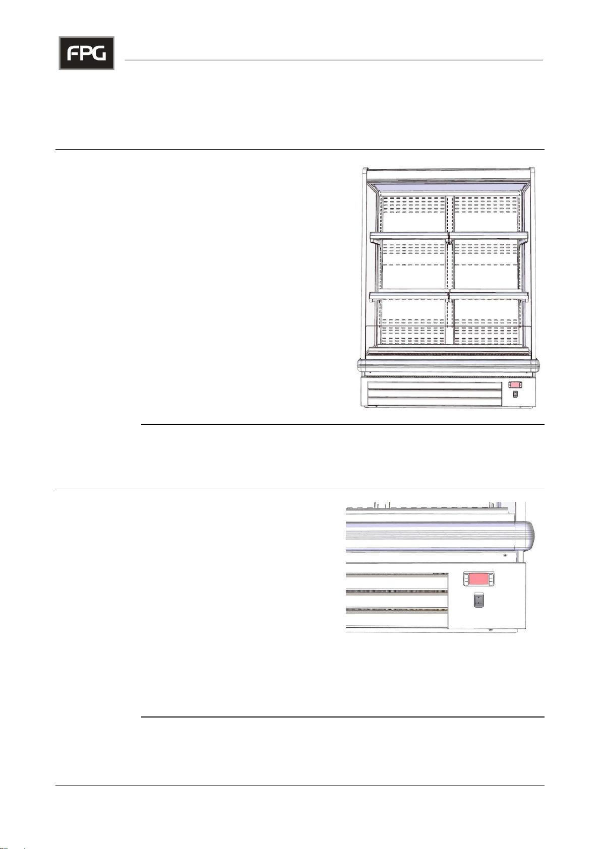
Interior............................................................................................................................................................. 14
Side Glass ................................................................................................................................................ 14
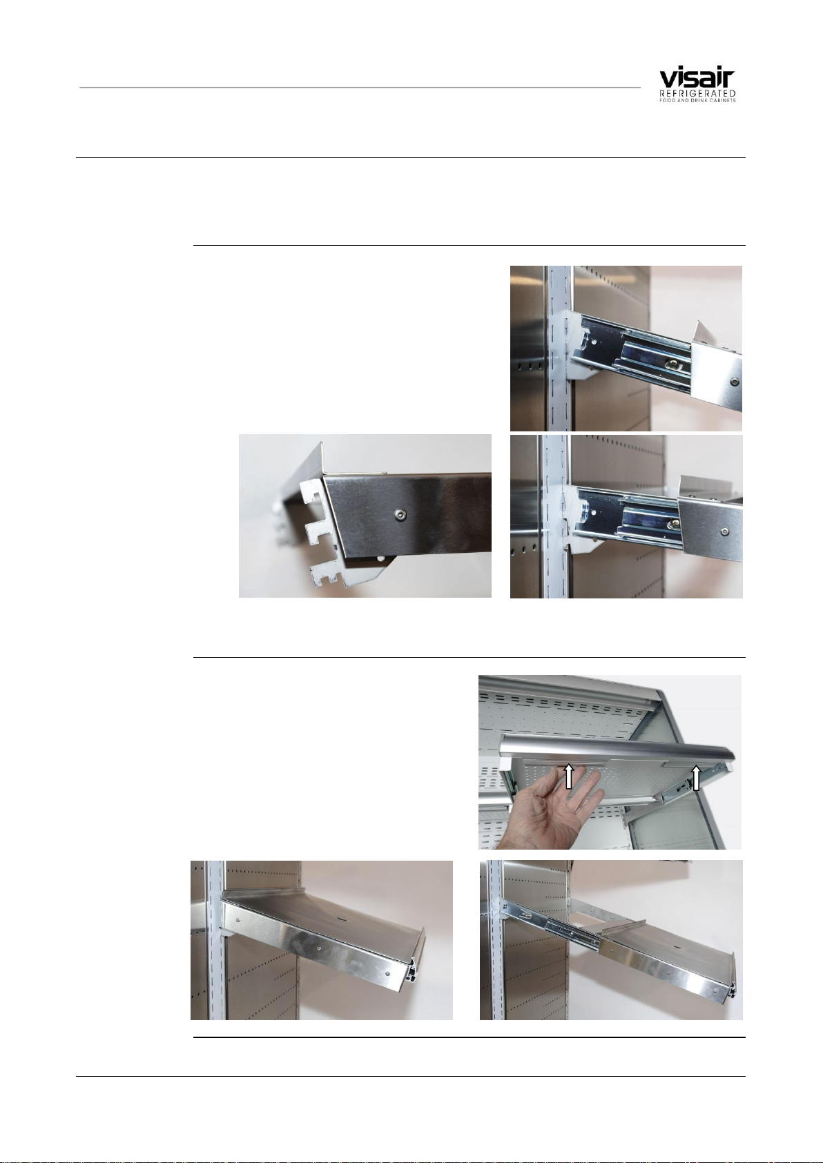
Shelves..................................................................................................................................................... 14
Base Tray ................................................................................................................................................. 14
Back Plates............................................................................................................................................... 14
Cleaning the Base Cavity......................................................................................................................... 15
Fan Deck and Drain Hole......................................................................................................................... 15
Condensate Capacity Warning................................................................................................................. 15
Cleaning Materials.................................................................................................................................... 15
Cooling Coil and Probes........................................................................................................................... 15
Mandatory Cleaning Routines...................................................................................................................... 16
Warning.................................................................................................................................................... 16
Air Vents................................................................................................................................................... 16
Condenser Radiator ................................................................................................................................. 16
Inspection and Rectification ..................................................................................................................... 16
INSTALLATION ................................................................................................................17
Regulations .................................................................................................................................................... 17
Compliance with Local Requirements...................................................................................................... 17
Setting Up....................................................................................................................................................... 17
Unpacking................................................................................................................................................. 17
Cabinet Preparation.................................................................................................................................. 17
Positioning the Cabinet ............................................................................................................................ 17
Power Supply and Earthing...................................................................................................................... 17
Isolation .................................................................................................................................................... 18
Location.......................................................................................................................................................... 18
Ventilation................................................................................................................................................. 18
Draughts................................................................................................................................................... 18
SERVICING.......................................................................................................................19
Electrical Protection...................................................................................................................................... 19
Circuit Breaker.......................................................................................................................................... 19
Lighting........................................................................................................................................................... 19
Caution ..................................................................................................................................................... 19
LED Lighting Strips................................................................................................................................... 19
LED Power Supplies................................................................................................................................. 19

IN –VA10 - 5 - © Future Products Group
Refrigeration Equipment............................................................................................................................... 20
Caution ..................................................................................................................................................... 20
Refrigeration Equipment........................................................................................................................... 20
Compressor.............................................................................................................................................. 20
Condensate Disposal ............................................................................................................................... 20
ACR Fault Finding Guide ......................................................................................................................... 21
Access to Condenser Radiator and Control Gear.................................................................................... 21
Control Gear............................................................................................................................................. 22
Evaporator Fan Replacement .................................................................................................................. 22
Evaporator Coil......................................................................................................................................... 22
Air Ducts and Grills................................................................................................................................... 22
Temperature Regulator XR40CX ............................................................................................................. 23
FPG Settings............................................................................................................................................ 27
Dixell Default Settings .............................................................................................................................. 27
XR40CX Alarm Signals ............................................................................................................................ 29
XR40CX Connections .............................................................................................................................. 29
SPECIFICATIONS.............................................................................................................30
Mechanical ..................................................................................................................................................... 30
Electrical......................................................................................................................................................... 30
Cabinet Performance..................................................................................................................................... 31
Refrigerated Section Performance........................................................................................................... 31
Controller Settings ........................................................................................................................................ 31
Dixell XR40CX Settings............................................................................................................................ 31
Mains Lead ..................................................................................................................................................... 31
Lead Replacement ................................................................................................................................... 31
Compliance .................................................................................................................................................... 32
Safety Aspects.......................................................................................................................................... 32
Hazardous Substances ............................................................................................................................ 32
Operational Safety.................................................................................................................................... 32
Improvements ................................................................................................................................................ 32
Ongoing Development.............................................................................................................................. 32
ELECTRICAL CIRCUIT DIAGRAMS................................................................................33
Model: IN –VA10-A004/5......................................................................................................................... 33
SPARE PARTS .................................................................................................................34
Cabinet Serial Number............................................................................................................................. 34
MECHANICAL DRAWINGS..............................................................................................35
Inline Visair IN –VA10-A004................................................................................................................... 35
Inline Visair IN –VA10-A005................................................................................................................... 36

Part No. 25553 Rev. J November 2017 - 6 - Visair Refrigerated Cabinets
INTRODUCTION
Welcome
VISAIR CABINETS
-
INTRODUCTION
Future
Products
Group (FPG)
Welcome to the world of FPG! Our products are designed and engineered to
give you the optimal performance that you deserve with innovative visual
merchandising appeal.
We are confident that you will be delighted with your state of the art Inline Visair
food service cabinet, and that it will become a valued appliance in your store.
Guidance and
Help
Any new appliance can seem very complex and confusing at first glance. To
ensure you receive the utmost benefit from your new Inline Visair cabinet, there
are two things you can do.
Before operating the cabinet, please read the instruction book carefully and
follow its recommendations. The time taken will be well spent. These
instructions both general and technical tell you how to operate and look after
your Inline Visair food service cabinet so that you can receive the full
benefits that this cabinet has to offer.
These instructions cannot, however, cover all eventualities. If you are
unsure of any aspect of the installation, instructions or performance of your
cabinet, contact your dealer promptly or contact us via email to
support@fpgworld.com.
Warranty
VISAIR CABINETS
-
INTRODUCTION
Warranty
Period
Future Products Group Limited warrants, to the original purchaser of an FPG
manufactured food service cabinet that for ONE YEAR (12 months), from the
date of purchase, any defect in workmanship or material resulting in the product
malfunctioning while under correct use will be rectified.
Liability under this warranty is limited to replacing or repairing a part, without
charge.
Continued on next page

IN –VA10 - 7 - © Future Products Group
Warranty cont.
VISAIR CABINETS -INTRODUCTION
Liability
Exceptions
Liability under this warranty does not include:
Any loss, or damage or expenses directly or indirectly arising from use or
inability to use the product or from any other cause.
Any part of the cabinet which has been subject to misuse, neglect,
alteration, incorrect installation, accident, or damage caused by
transportation, use of abrasive or caustic chemicals, flooding, fire or acts of
God.
Damage, resulting from failure to have the cabinet regularly serviced every
three months by a refrigeration engineer. NB: You will be required to
provide copies of service records in the event of compressor failure.
Any damage or malfunction resulting from the use of non-FPG supplied
spare parts.
Specific
Exclusions
The following are specifically excluded from warranty:
Breakage of glass or plastic components or the replacement of LED lighting
strips or gaskets.
Maladjustment of the electronic refrigeration controller, by an unqualified
person.
Failure resulting from a lack of routine compressor / radiator cleaning.
Failure to re-assemble the cabinet correctly after cleaning.
Fair wear and tear.
Assessment
The liability under this warranty is dependent on an assessment by FPG, to
determine the defect in workmanship or materials.
Time Limit
FPG does not guarantee that any service to be performed under this warranty
will be carried out within any particular time limit.
Caution
No warranty claim will be accepted unless authorised by FPG prior to
commencement of service.

Part No. 25553 Rev. J November 2017 - 8 - Visair Refrigerated Cabinets
OPERATION
Cabinet Layout
VISAIR CABINETS
-
OPERATION
Visair Cabinet
Configuration
This is a fully self-contained, stand-
alone, open front cabinet, with glass side
panels and LED lighting.
The cabinet is available with two shelf
configurations. See Mechanical
Drawings.
It is fitted with a condensate disposal
boil-off unit, in the base of the cabinet.
The controls and refrigeration equipment
are mounted in the base of the cabinet.
Cooling air for the refrigeration system is
drawn in from the front of the cabinet,
and exhausts from slots on the cabinet
top.
Vaporised condensate mixes with this
air flow and also exhausts from the top
of the cabinet.
Controls
VISAIR CABINETS
-
OPERATION
Power Switch
and
Refrigeration
Controller
The main power switch is located on
the front base panel, on the right hand
side.
This is the only operator control, and it
switches both the lighting and
refrigeration on and off.
The refrigeration controller indicates
the cabinet temperature, by sensing
the returned air, entering the cooling
coil.
The controller is pre-set for correct cabinet functioning. The set-point
temperature is lower than the display area temperature, as the condenser
operates in response to the temperature of the air exiting the cooling coil.
The controller must only be adjusted by a qualified service person.

IN –VA10 - 9 - © Future Products Group
Preparation
VISAIR CABINETS
-
OPERATION
Shelf Location
and Ticketing
All shelves are adjustable in height and can easily be moved up or down, to
match product size. The front edges of the shelves are profiled to carry
ticketing/labels.
Shelf
Adjustment
To alter the shelf position, slide the brackets
upwards and disengage them from the
support pillar.
Insert the brackets in the new position and
push them down firmly.
The brackets can be inserted in two
positions, allowing the shelves to be either
horizontal or sloping downwards.
Make sure shelf brackets are pushed down as far as they can go. Failure to do
this may result in shelf collapse, when loaded with product.
Two-piece
Shelf Loading
Position
Each two-piece shelf is fitted with
runners, enabling it to be pulled forward
for easy loading.
Using two hands, depress the two
locking bars located under the front
edge of the shelf, to release it.
When returning the shelf to its normal
position, push it in firmly, until both
locking bars latch into position.

Part No. 25553 Rev. J November 2017 - 10 - Visair Refrigerated Cabinets
Preparation cont.
VISAIR CABINETS -OPERATION
Shelf Load
Restrictions
Two-piece pull out shelves must not be loaded with more than 15kg of
evenly distributed products per shelf.
Full width fixed shelves must not be loaded with more than 35kg of
evenly distributed products per shelf.
Switch Power
On
Turn on the power switch, the cabinet light
and fans will run, and after a short delay,
the compressor will run and the cabinet
temperature will begin to fall.
The temperature controller is pre-set to
maintain the cabinet temperature between
2°C and 4°C.
It should not need adjustment.
Load Cabinet
After the cabinet has run for a 30 minute initial cool-down period, load it with
pre-chilled products.
The cabinet is designed to maintain the temperature of pre-chilled products.
If warm product is introduced, there could be a delay before the
temperature falls to the normal operating level.
Loading
Restrictions
It is important to leave adequate free space for the refrigerated air to circulate
within the cabinet.
A minimum space of 40mm must be maintained above canned drinks, or other
cylindrical containers.
The air grills at the front of the cabinet must not be covered or restricted.
Defrost Cycle
Defrosting of the evaporator coil is fully automatic.
Note that the defrost times are set from when the cabinet is first turned on. If
they are required at a particular time, you must turn on the cabinet two hours
before the first defrost required. The cycles will then occur every two hours,
provided the cabinet is not switched off.
Each defrost cycle terminates as soon as the temperature of the evaporator fins
rises to a level indicating that all ice has melted.
This active defrost system improves the energy efficiency of the cabinet, and
minimises temperature fluctuations.

IN –VA10 - 11 - © Future Products Group
Routines
VISAIR CABINETS
-
OPERATION
After Hours
Ideally, cabinets should not be turned off after hours or at night.
If the cabinet is turned off, transfer the products to a cool store. When the
cabinet is turned on again, allow it to run for 30 minutes before returning the
chilled products.
Cleaning
It is recommended that cabinets be cleaned at the end of the working day, since
they need to be shut down for this. See Cleaning section.
De-frost Cycle
Defrosting of the evaporator coil is fully automatic, taking place every two hours.
If you suspect that the defrost system is not working properly, have it checked
by a qualified service person.
Operators must not attempt to adjust the refrigeration controller.
Temperature
Checks
Cabinet temperatures should be routinely checked, to confirm satisfactory
operation.
The refrigeration controller shows the temperature of the circulating air, as it
enters the cooling coil. This will be slightly higher than the air temperature in
the display area, so a temperature probe should be used to check product
temperatures.
To avoid misleading temperature measurements, do not take a readings within
20 minutes of a defrost cycle.
Warning-
Flammable
Products
Do not store explosive substances, such as aerosol cans with a
flammable propellant, in this appliance.
Equipment Disposal
VISAIR CABINETS
-
OPERATION
Specialist
Disposal
Specialist disposal procedures are required for the safe removal of refrigerant
gasses and potentially flammable foam materials.
Pentane, Dimethyl Ether, Isobutene, Butane and Propane may be present.

Part No. 25553 Rev. J November 2017 - 12 - Visair Refrigerated Cabinets
TROUBLE SHOOTING
FAULT
POSSIBLE CAUSE
REMEDY
Cabinet does not
operate/start
The mains isolating switch on
the wall, circuit breaker or fuses
are off at the power board
Turn isolating switch circuit
breaker or fuses on
The power switch on the cabinet
is OFF
Turn the power switch ON
The internal MCB has tripped off
or failed
Have wiring checked and
reset or replace breaker
The power switch is faulty
Have the switch replaced
Refrigerated Cabinet does
not reach temperature
Ventilation grills are blocked
Vacuum or remove blockage
Product blocking air grill
Place product on shelves
Thermostat needs adjustment
Adjust refrigeration controller
Ambient > 25C & 60%RH
Adjust store air conditioning
Evaporator coil iced up
De-ice coil, check defrost
parameters, replace controller
if found faulty
Condenser radiator blocked
Remove dust and debris
Refrigeration controller faulty
Replace controller
Temperature probe damaged
Replace temperature probe
Fans not operating
Have fans checked/replaced
HP pressure switch triggered
Manually reset switch
LP pressure switch triggered
Allow switch to auto reset. If it
doesn’t reset, check for leaks
(Clear the alarm indication, by turning off the power to reset the controller)
Condensate Overflows
Defrost cycle unsuitable
Have defrost cycle adjusted
Boil off element failed
Replace element
Boil-off control module failed
Check/replace control module
Cabinet lights not working
LED strip has failed
Replace LED strip
LED power supply has failed
Replace LED power supply
Internal circuit breaker has
tripped
Have wiring checked and
reset circuit breaker
Aluminium parts corroded
Caustic detergent damage
Order replacement parts
Service
Personnel Only
The table entries in italics indicate actions to be taken only by qualified Service
Personnel.

IN –VA10 - 13 - © Future Products Group
CLEANING
Cautions
VISAIR CABINETS
-
CLEANING
Power
ALWAYS TURN THE POWER SUPPLY OFF BEFORE CLEANING.
Water
THIS UNIT IS NOT WATERPROOF. DO NOT USE A WATER JET SPRAY TO
CLEAN THE INTERIOR OR EXTERIOR OF THIS CABINET.
Exterior
VISAIR CABINETS
-
CLEANING
Louvers
Use a vacuum cleaner to remove dust and fluff from the
ventilation louvers on the front and top of the cabinet.
This will maintain the refrigeration efficiency, and prevent
overheating.
Painted and
Metal Surfaces
Painted, galvanised steel or aluminium surfaces should be cleaned with hot
soapy water then dried off with paper towel or dry cloth. DO NOT clean surfaces
with abrasive pads or cleaners as paint, galvanised steel and aluminium
surfaces will be damaged.
Glass
All glass should be cleaned using a good quality glass cleaner and a clean
cloth.
DO NOT clean glass with abrasive pads or cleaners as the glass will be
damaged.

Part No. 25553 Rev. J November 2017 - 14 - Visair Refrigerated Cabinets
Interior
VISAIR CABINETS
-
CLEANING
Side Glass
The inside surfaces of the side panels are most easily cleaned after the
products and shelves have been removed.
Shelves
The shelves can
be cleaned in
place, or lifted off.
The complete
shelf module can
be removed by
lifting it vertically, to disengage the
support brackets from the back panel.
Base Tray
The base tray is mounted on runners, and
can be pulled forward for cleaning.
Back Plates
Once the shelves have been removed, and
the base drawer slightly opened, the back
plates can be removed.
Lift the plate vertically, to disengage it from
the bottom location slot, pull it forward, then
lower it to disengage it from the top location
slot. It can now be removed for cleaning.
Continued on next page

IN –VA10 - 15 - © Future Products Group
Interior cont.
VISAIR CABINETS -CLEANING
Cleaning the
Base Cavity
With the base tray pulled out, sweep out,
or use a vacuum cleaner, to remove any
debris from the base cavity.
A Wet-and-Dry vacuum cleaner should be
used, since there is likely to be some water
in the bottom.
Fan Deck and
Drain Hole
After removing the fixing screws, the fan deck
can be lifted and unplugged from the cabinet
for thorough cleaning.
Be careful not to trap the cables when it is
replaced.
Check the drain hole is clear of debris.
Condensate
Capacity
Warning
The condensate tray and boil off heater is only designed to handle cooling-coil
defrosting water that drains from the well during normal operation. The boil off
container has a capacity of five litres.
When cleaning, DO NOT fill the well with liquid or attempt to hose it out, as the
condensate tray will overflow and leak onto the floor.
Cleaning
Materials
Steel trays, shelves, grills etc. should be cleaned with hot soapy water then
dried off with paper towel or dry cloth.
DO NOT use abrasive pads or cleaners as these may damage surfaces.
Warning: Dishwasher detergent may damage anodised aluminium parts.
Cooling Coil
and Probes
With the back plates removed, the cooling coil is
exposed. No cleaning is normally required, but if there
is any debris visible, carefully remove it with a vacuum
cleaner.
Be very careful not to bend or distort the fins of the
cooling coil, as this would reduce the airflow.
Also be careful not to move or disturb the location of the
two temperature probes. One is in free air, and the
other is inserted between the fins of the coil.
Continued on next page

Part No. 25553 Rev. J November 2017 - 16 - Visair Refrigerated Cabinets
Mandatory Cleaning Routines
VISAIR CABINETS
-
CLEANING
Warning
It is mandatory to have the radiator fins cleaned periodically, by a
refrigeration engineer. (see Servicing section).
Failure to carry out routine cleaning/servicing schedules will void the
warranty on the refrigeration equipment.
To maintain optimum performance, cleaning must be regular and thorough.
It is recommended that a schedule of cleaning operations should be drawn up.
Air Vents
Vacuum away any dust and fluff
from all air vents.
The top air vents must be kept
free of blockages at all times.
Condenser
Radiator
Pull off the louver panel
and vacuum away any dust
and fluff from the
condenser radiator, to
maintain good refrigeration
efficiency.
Be careful not to bend or
distort the radiator fins.
In locations with elevated
levels of air born dust or
fluff, the radiator should be
checked frequently and an
appropriate cleaning
schedule established.
Inspection and
Rectification
As part of the cleaning routine, the controls, mechanical parts and electrical
wiring should be inspected for damage, deterioration or need of adjustment.
If any small faults are found, have them attended to promptly by a competent
serviceman. Don’t wait until they cause a complete breakdown.

IN –VA10 - 17 - © Future Products Group
INSTALLATION
Regulations
VISAIR CABINETS
-
INSTALLATION
Compliance
with Local
Requirements
It is very important that your food cabinet is installed correctly and is operating
properly before use. Installation must comply with local electrical, health &
safety and hygiene requirements.
Setting Up
VISAIR CABINETS
-
INSTALLATION
Unpacking
Unpack and check unit for damage and report any damage to the carrier and
supplier. Report any deficiencies to your supplier.
Cabinet
Preparation
Remove all tapes, ties and packers, used to prevent movement during transit.
Pull the base drawer open to check for packing materials in the well.
Positioning the
Cabinet
Position the cabinet in its
allocated working position, and
remove the front louvered panel.
With the feet raised, rollers at
front and rear enable easy
manoeuvrability.
Using a spirit level, adjust each
front foot to ensure the cabinet is
level from front to back and side to side. If the floor is not level, place packing
under one of the castors.
Power Supply
and Earthing
The cabinet is fitted with a four metre
mains lead, located on the top of the
cabinet at the centre rear.
If the supply cord is damaged, it must
be replaced by a special cord or
assembly available from the
manufacturer or its service agent.
An EMI line filter is mounted adjacent to the mains inlet. If the cabinet is to be
hard wired, this must only be done by a suitably qualified person.
Before connecting to the power supply, check that the local supply is correct to
that shown on the cabinet label.
WARNING - THE CABINET MUST BE EARTHED/GROUNDED
Continued on next page

Part No. 25553 Rev. J November 2017 - 18 - Visair Refrigerated Cabinets
Setting Up cont.
VISAIR CABINETS -INSTALLATION
Isolation
If the cabinet is not connected to an outlet socket, but is hard wired to the mains
supply, a means of isolation must be provided.
If a plug and socket are used, they should still be accessible after the cabinet is
installed.
Location
VISAIR CABINETS
-
INSTALLATION
Ventilation
The front louvers and vents located on the top of the cabinet must never be
obstructed. If obstructed the cabinet may overheat and cause an electrical
malfunction.
If the cabinet is installed in an alcove, or under any structure, a minimum
clearance space of 200mm must exist above the cabinet top.
Before use, operate the cabinet for 1-2 hours to remove any fumes or odours,
which may be present.
Draughts
The door-less cabinet features an “air curtain” to retain the cold air within the
cabinet. A “curtain” of cold air falls from a linear vent, across the top of the open
cabinet front, to be re-circulated through the evaporator cooling coils.
The cabinet should not be sited where strong draughts will deflect the “air
curtain”. If this happens, excess condensation will form on the products, and
cooling will be less effective.

IN –VA10 - 19 - © Future Products Group
SERVICING
Electrical Protection
VISAIR CABINETS
-
SERVICING
Circuit Breaker
The lighting and control circuits are protected by a
circuit breaker, located on the control panel.
The louvered panel must be removed to access the
circuit breaker.
If the breaker cannot be reset, call an electrician to
check the circuits.
Lighting
VISAIR CABINETS
-
SERVICING
Caution
DO NOT service the lights, without isolating the cabinet at the main switch or
unplugging it from the electricity supply.
LED Lighting
Strips
Light is provided by an LED strip, under the
top of the cabinet.
The LED modules have
a very long life, but if
they fail, the complete
strip should be
replaced.
The LED strips are self-
adhesive, with soldered
connections.
Ensure correct polarity when reconnecting.
Be sure to replace this plastic cover.
LED Power
Supplies
The LEDs are fed with a 24Vdc
constant voltage. They consume
approximately 17 W per metre of strip
length.
The power supply is located behind the
back panel, to the side of the mains
connector.

Part No. 25553 Rev. J November 2017 - 20 - Visair Refrigerated Cabinets
Refrigeration Equipment
VISAIR CABINETS
-
SERVICING
Caution
DO NOT attempt to service the refrigeration equipment without isolating
the cabinet from the mains supply.
Refrigeration
Equipment
The compressor,
condenser fan and
condensate disposal
system are mounted in
the base of the
cabinet, behind the
condenser radiator.
Unscrew the lower
back panel to gain
access.
Compressor
The scroll type compressor is
hermetically sealed.
It is fitted with a dryer, an auto reset
Low Pressure and a manual reset
High Pressure switch.
Two access ports are provided for
pressure monitoring and charging with
refrigerant.
Condensate
Disposal
The condensate
disposal system
consists of a water tray,
a water level detector
and a boil-off element
with an over
temperature cut-out.
If the element fails, it
may be replaced by
springing it from the
mounting bracket. Cut
and splice the leads
and protect with heat-
shrink sleeves.
Continued on next page
This manual suits for next models
1
Table of contents
Other FPG Refrigerator manuals
Popular Refrigerator manuals by other brands

KitchenAid
KitchenAid KSRP25FSWH - ARCHITECT Series: 25 cu. Ft. Superba... parts manual

Dometic
Dometic RM2193 Installation & operating instructions

Whirlpool
Whirlpool ET12LK Use and care guide

Electrolux
Electrolux ER 7659B Installation and instruction manual

LG
LG GL-B181RDSW owner's manual

KitchenAid
KitchenAid KBFO42FTX00 cabinet parts