Fröling S1 Turbo Quick start guide

www.froeling.com

P0220613_en
Energy systems
General
2 3
Valued Froling Partner
Here at Froling we want to provide the environmentally friendly, economical and userfriendly energy
system solutions that people want.
This brochure presents our range and offers orientation for planning or implementation of heating
systems, and contains the most current variants.
We reserve the right to make technical changes without prior notice.
If you need more information or suggestions for hydraulic systems, our customer service department,
and of course our internal technical department, will always bei happy to assist.
Froling G.m.b.H
Contents
1) Sensors . . . . . . . . . . . . . . . . . . . . . . . . . . . . . . . . . . . . . . . . . . . . . . . . . . . . 3
1.1) General sensors
1.2) Room sensor FRA
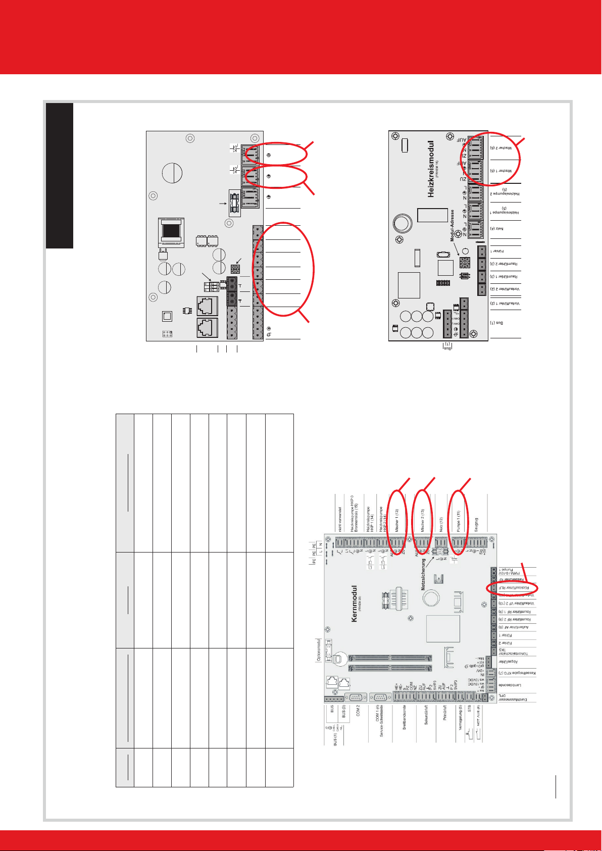
2) Bus system . . . . . . . . . . . . . . . . . . . . . . . . . . . . . . . . . . . . . . . . . . . . . . . . . 4
2.1) Heating circuit module
2.2) Hydraulic module
2.3) Room console RBG 3200 / RBG 3200 Touch
2.4) Bus cable
3) Sensor functions for standard systems . . . . . . . . . . . . . . . . . . . . . . . . . . . . 5
3.1) Top store (sensor 0.1)
3.2) Bottom store (sensor 0.2)
3.3) DHW tank (sensor 0.3)
3.4) Bottom DHW tank (sensor 0.4)
3.5) Oil/gas boiler (sensor 0.5)
3.6) Mid store (sensor 0.6)
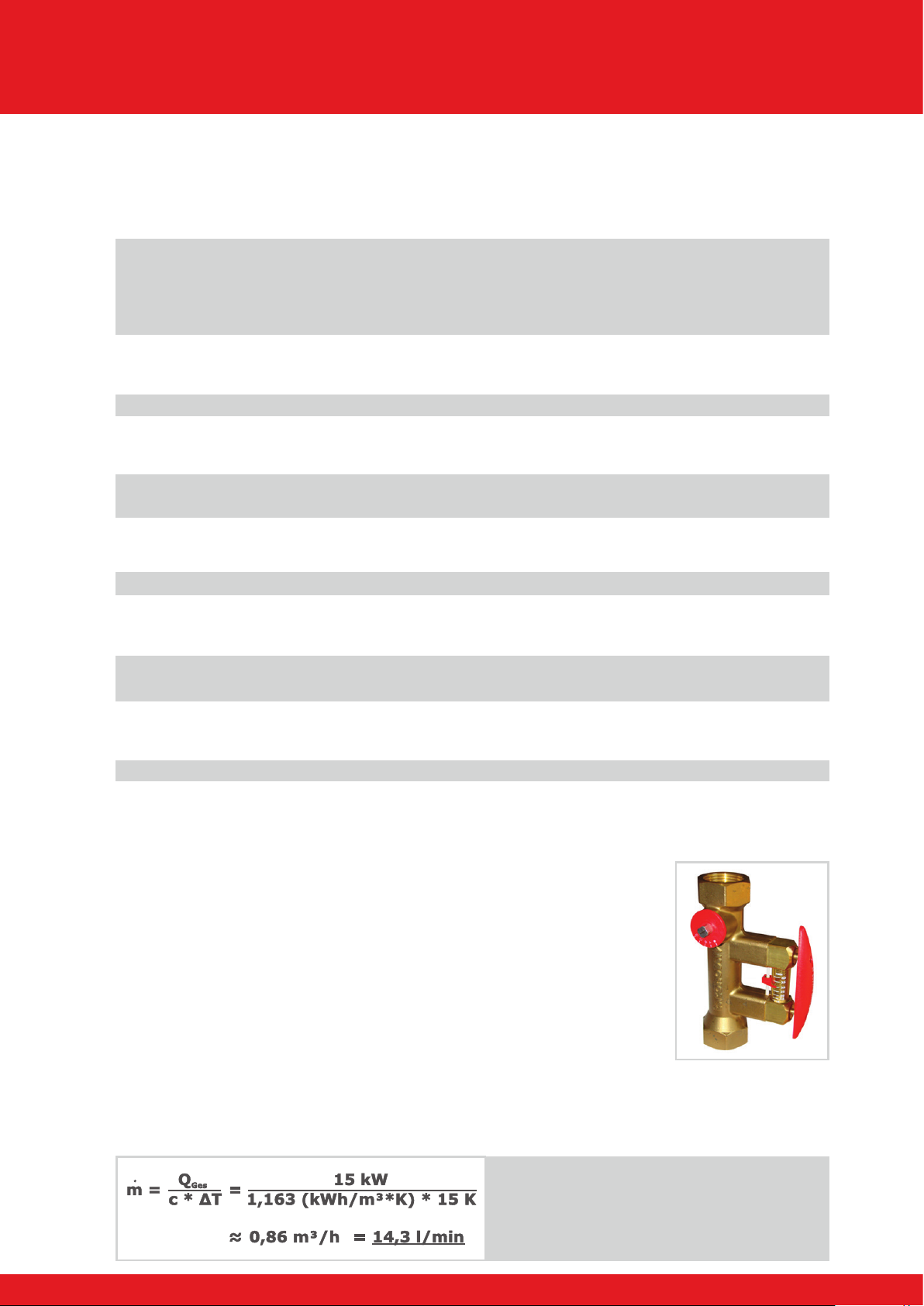
4) Balancing valve . . . . . . . . . . . . . . . . . . . . . . . . . . . . . . . . . . . . . . . . . . . . . . 5
4.1) Setting example
5) Connection instructions . . . . . . . . . . . . . . . . . . . . . . . . . . . . . . . . . . . . . . . . 6
5.1) HKP0 - output for oil/gas boiler connections
5.2) Isolating valve
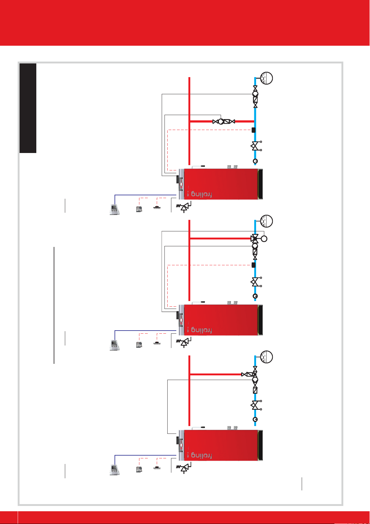
Layout proposals . . . . . . . . . . . . . . . . . . . . . . . . . . . . . . . . . . . . . . . . . . . . . . . 7
Connections . . . . . . . . . . . . . . . . . . . . . . . . . . . . . . . . . . . . . . . . . . . . . . . . . 7
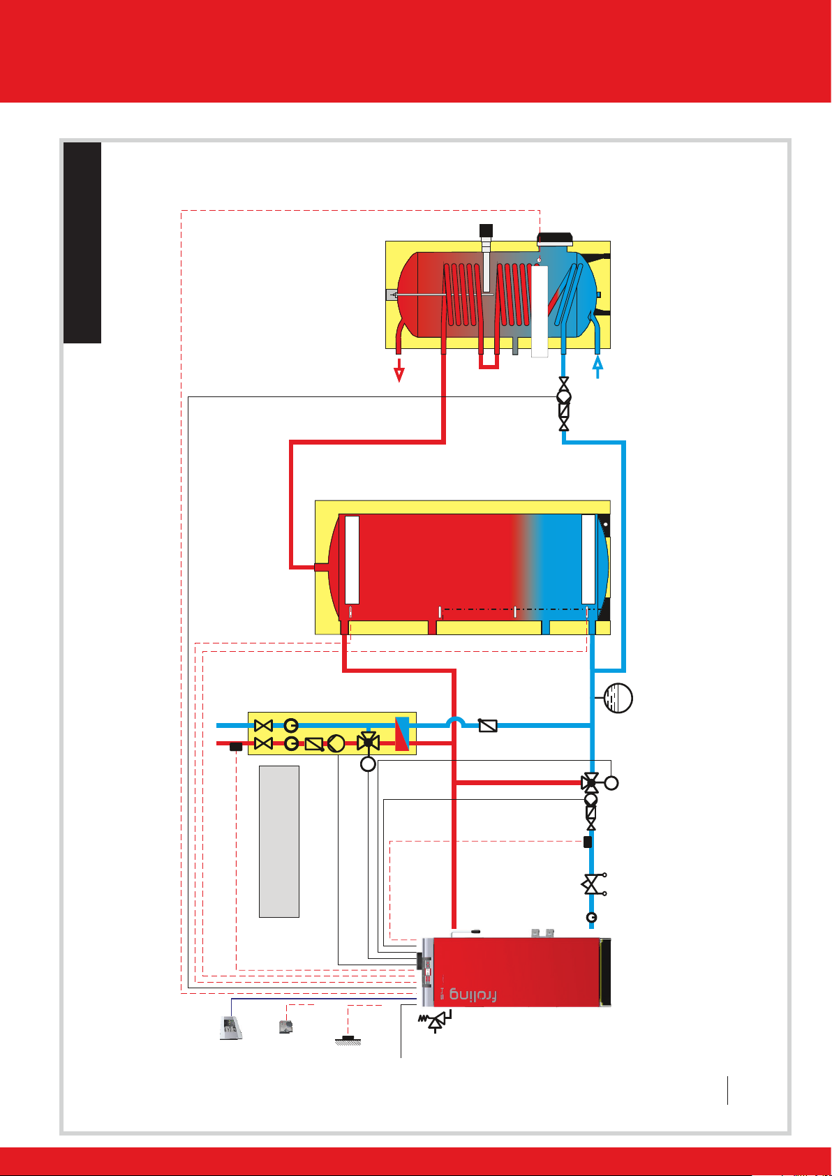
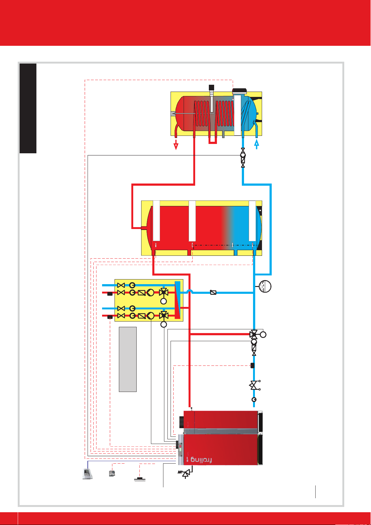
RLA - S/SP 3200 / System 1.S013 . . . . . . . . . . . . . . . . . . . . . . . . . . . . . . . . 8/9
System 1.SP003 / System 1.S002 . . . . . . . . . . . . . . . . . . . . . . . . . . . . . . 10/11
System 1.S040 / System 1.S007 . . . . . . . . . . . . . . . . . . . . . . . . . . . . . . . 12/13
System 1.SP001 / System 1.S008 . . . . . . . . . . . . . . . . . . . . . . . . . . . . . . 14/15
System 1.S035 / System 2.S001 . . . . . . . . . . . . . . . . . . . . . . . . . . . . . . . 16/17
System 2.S021 / System 2.S034 . . . . . . . . . . . . . . . . . . . . . . . . . . . . . . . 18/19
System 2.S003 / System 2.S011 . . . . . . . . . . . . . . . . . . . . . . . . . . . . . . . 20/21
System 12.S001 / Coupled tank systems . . . . . . . . . . . . . . . . . . . . . . . . . 22/23

www.froeling.com
P0220613_en
Energy systems
General
The following pages provide a general description of the most important components and sensor
functions used in the systems.
Due to the wide range of programming options with the Lambdatronic S 3200,
the sensor descriptions may vary for specic systems that have been adapted
for customers.
1) Sensors
1.1) General sensors
Technical specications for the sensors listed above:
Resistance sensor type: KVT 20; approx. 2kΩ at 20°C
Maximum cable length: 40m with shielded cable in the same building
Immersion sensor
e.g. as boiler-, DHW tank- or store-sensor
Collector sensor
for solar systems
Contact sensor
e.g. as return feed sensor or outfeed sensor
External sensor
for weather-activated heating circuit control
1.2) Room sensor FRA
Analogue room sensor (disengageable) with selector switch mode
and adjusting wheel for temperature.
Connection with inuence Connection without inuence
of room temperature: of room temperature
!
Technical specictions:
Resistance sensor type: FRA; approx. 3,5kΩ at 20°C (switch set to automatic
mode and rotating wheel in middle position)
Maximum cable length: 40m with shielded cable in the same building

P0220613_en
General
4 5
Energy systems
2) Bus system
2.1) Heating circuit module
Wall casing with board for controlling
A contact sensor for controlling a heating circuit is included.
2.2) Hydraulic module
Wall casing with board for controlling
Additionally 2 immersion sensors are included, which can be used for the following
purposes:
2.3) Room console RBG 3200 / RBG 3200 Touch
Digital multi-functional room device for easy operation of the
heating system from the living area - for optimum room tem-
perature and ease of use.
The latest data access using self-explanatory menu navigation.
Max. 7 units can be used per system.
2.4) Bus cable
The connection to the 5-pin plugs should be carried out according to the
following diagram:
• 2 mixers
• 2 heating circuit pumps
• 2 analogue room sensors
• Bus connection to main control
• max. 8 units can be used per system
• 2 pumps, using max. 6 sensors
• max. 8 units can be used per system
(1 hydraulic module with 3 immersion sensors is included
in boiler delivery)
• Storage tank management
for speed-controlled storage tank loading via 2 sensors. Top store sensor releases
heating circuit pumps.
• Differential temperature control for DHW-tank
for controlling the DHW-tank loading pump; depending on the top storage tank tem-
perature and DHW-tank temperature.
• Solar systems and feeder pumps
• Circulation pump
• Maximum cable length: 500m
(expandable with busrepeater / cascade module)
• Cable type LIYCY paired 2x2x0.5, CAT5 or CAT6 should be used for the bus
connections between the individual modules (NOT TELEPHONE CABLE, such as type
JY(ST)Y 2x2x0.6)
+UBUS
CAN H
CAN L
+UBUS
CAN H
CAN L
Braided shield
White
Green
Yellow
Brown
Braided shield
White
Green
Yellow
Brown

www.froeling.com
P0220613_en
General Energy systems
3) Sensor functions for standard systems
3.1) Top store (sensor 0.1)
3.2) Bottom store (sensor 0.2)
3.3) DHW tank (sensor 0.3)
3.4) Bottom DHW tank (sensor 0.4)
3.5) Oil/gas boiler (sensor 0.5)
3.6) Mid store (sensor 0.6)
4) Balancing valve
If the systems are not correctly balanced there is normally an exces-
sively high ow volume through the boiler. As a result there is a rela-
tively low temperature difference between the boiler ow and return.
The balancing valve SETTER Bypass SD, from the Froling product
range enables precise and simple adjustment of the ow rate in
l/min and thereby an optimal temperature difference.
There is only ow through the bypass if the handle is pressed. The
volume ow rate in l/min can be set using the scale of the meter
integrated to the bypass, reading from the lower edge of the oater.
There is no need to spend time determining settings using diagrams
and other aids.
4.1) Setting example
Log wood boiler S4 15kW, temperature difference 15K:
• Heating circuit release for the connected heating circuits (standard value: 30°C)
• Heat source for difference control of the DHW tank loading pump(s)
• Start signal for automatic ignition
• Release of a connected oil/gas boiler
• Difference measurement of boiler sensor for pump switching conditions
• Start signal for DHW tank loading pump
• Difference measurement of heat source (boiler or storage tank system-dependent)
• Reference sensor for solar integration
• Heating circuit release for oil/gas operation (system-dependent)
• Oil/gas boiler base temperature monitoring (switch valve / pump)
This means:
To get a temperature difference of 15K
it is almost possible to set the output in
kW as the volume ow rate in l/min at the
balancing valve.
• Loading criterion of the pellets unit (SP Dual)

P0220613_en
General
6 7
Energy systems
5) Connection instructions
5.1) HKP0 - output for oil/gas boiler connections
5.2) Isolating valve
If an isolating valve is connected to a speed-controlled pump outlet, an RC element must
be used. Furthermore, the minimum speed for the pump outlet in use must be set to 100%
in the control.
Connection hydraulic module: Connection core module:
Connect the outer cable L(bn):
• to the outer cable of the respective mains supply of the module or
• to the core module, output HCP0/burner relay at pin “LV”
Core module
L1
N
To oil boiler control:
floating contact for burner
release
Note:
Valve electroless
AB-B and 1-3
Isolating valve 1“ Isolating valve
1 1/4“ and 1 1/2“

www.froeling.com
P0220613_en
General Energy systems
Number Name on connection board Function Connection board
1 Pumpe 1 Pump 0.1 Hydraulic module Adress 0
2 Pumpe 2 Pump 0.2 Hydraulic module Adress 0
3 Fühler 1 - 6 Temp.sensor 0.1 - 0.6 Hydraulic module Adress 0
4 Pumpe 1 Pump 1 Core module
5 Rücklauffühler RLF Return sensor Core module
6 Mischer 1 Return feed m./Mixer1 Mixer 1 on Core module
7 Mischer 2 Mixer 2 Core module
8 Mischer 1/2 Mixer 3-18 on each heating circuit module
(max. 2 heating circuits are available)
AO-
P1
AO-
P2
6,3AT
Hydraulikmodul
(FRHYU 21)
Bus (2)
Fühler 1 (3)
Fühler 5 (7)
Netz (9)
Pumpe 2 (11)
Fühler 2 (4)
Fühler 4 (6)
Fühler 3 (5)
Pumpe 1 (10)
Fühler 6 (8)
Bus
(2)
2x Bus
(1)
Modul-Adresse
End-Jumper
Netzsicherung
CAN L
CAN H
+UBus
N
L
N
L
N
L
+
+
Note: Controller S3200; position numbers in brackets see operating instructions of the boiler controller
Hydraulic module
Heating circuit module
Core module
5
4
7
6
32
1
8
Layout proposals
Connections
Suggested layout proposal!

P0220613_en
Layout proposals
8 9
Energy systems
M
Pump assembly
FE
Log wood/combination boiler
S1 Turbo / S4 Turbo / SP Dual
Mains supply
230V
Room sensor
(Option)
External sensor
Mains supply
230V
Room sensor
(Option)
External sensor
Mot.
mixing valve 1
Mains supply
230V
Room sensor
(Option)
External sensor
Return sensor
(Core module) Pump 0.1
Pump 1
Pump assembly
OE
Return sensor
(Core module)
Pump 0.1
Note: Controller S 3200
* In combination with a return mixer module again up to 18 heating circuits are available!
Note: With a return feed lift
a motorised mixing valve up to
17* heating circuits are available!
usingNote: With a return feed lift using
pump assemby FE up to
18 heating circuits are available!
Note: With a return feed lift using
pump assembly OE up to
18 heating circuits are available!
Possibilities for return feed lift
Pump 0.1
Balancing
valve
Balancing
valve
Balancing
valve
RBG 3200 /
RBG 3200 Touch
(Option)
RBG 3200 /
RBG 3200 Touch
(Option)
RBG 3200 /
RBG 3200 Touch
(Option)
Log wood/combination boiler
S1 Turbo / S4 Turbo / SP Dual
Log wood/combination boiler
S1 Turbo / S4 Turbo / SP Dual
Pump assembly
ME
Suggested layout proposal! RLA - S/SP 3200

www.froeling.com
P0220613_en
Layout proposals Energy systems
MM
M
Room sensor
(Option)
External sensor
Mains
supply 230V
Flow temp. sensor 2
Heating circuit 2
Mot. mixing valve 2
Pump 0.1
Return sensor
(Core module) Mot. mixing
valve 1
Log wood/combination boiler
S1 Turbo / S4 Turbo / SP Dual
Note: S3200
Controller
Layered tank
Domestic
hot water
Cold
water
Pump 0.2
DHW tank
Unicell NT-S
Pump assembly
OE
Temp. sensor 0.3
Temp. sensor 0.1
Temp. sensor 0.2
RBG 3200 /
RBG 3200 Touch
(Option)
With heating circuit modules
(Bus connection) up to 17
heating circuits are available.
Balancing
valve
Suggested layout proposal! System 1.S013

P0220613_en
Layout proposals
10 11
Energy systems
MM MM
M
With heating circuit modules
(Bus connection) up to 18
heating circuits are available
Flow temp. sensor 1/2
Heating circuit 1/2
Mot. mixing valve 1/2
Temp. sensor 0.2
Temp. sensor 0.1
Temp. sensor 0.3
Pump 0.2
Domestic
hot water
Cold
water
DHW-tank
Unicell NT-S
Pump assembly
OE
Note: Controller SP3200 + Return mixer module
Return feed mixer
(Return mixer module)
Return sensor
(Core module)
Mains
supply 400V
Room sensor
(Option)
External sensor
Pump assembly
ME
Temp. sensor 0.6
RBG 3200 /
RBG 3200 Touch
(Option)
Balancing
valve
Pump 0.1
Layered tank
Log wood/combination boiler
S1 Turbo / S4 Turbo / SP Dual
System 1.SP003
Suggested layout proposal!

www.froeling.com
P0220613_en
Layout proposals Energy systems
MM
MM
Room sensor
(Option)
External sensor
Mains supply
230V
Flow temp. sensor 1/2
Heating circuit 1/2
Mot. mixing valve 1/2
Pump 0.1
Pump assembly
FE
Pump 0.2
Domestic
hot water
Cold
water
Pump assembly
OE
DHW tank
Unicell NT-S
Temp. sensor 0.6
(Collector sensor)
Pump 1
Note: Please set parameter in menu SOLAR, item SERVICE, SOLAR SYSTEM to “1”,
WHICH SENSOR IS USED FOR THE SOLAR COLLECTOR to “0.6” and
WHICH PUMP IS USED FOR THE SOLAR COLLECTOR to “Pump 1”.
Controller S3200, since version 50.04 B04.08
Temp. sensor 0.4
Place temp.
sensor 0.3
in upper
area
Temp. sensor 0.1
Temp. sensor 0.2
RBG 3200 /
RBG 3200 Touch
(Option)
With heating circuit modules
(Bus connection) up to 18
heating circuits are available
Log wood/combination boiler
S1 Turbo / S4 Turbo / SP Dual
Balancing
valve
Layered tank
Suggested layout proposal! System 1.S002

P0220613_en
Energy systems
Layout proposals
12 13
MM MM
M
AB(1)
A(2) B(3)
Mains supply
230V
External sensor
Room sensor
(Option) Flow temp. sensor 1/2
Heating circuit 1/2
Mot. mixing valve 1/2
Pump assembly
FE
Pump assembly
OE
DHW tank
Unicell NT-S
Temp. sensor 1.1
(Collector sensor)
Hydraulicmodule
Mains supply 230V
Pump 0.2
Domestic
hot water
Cold
water
Place temp.
sensor 0.3
in upper
area!
Address 1
Pump 0.1
Note: Please set parameter in menu SOLAR, item SERVICE, SOLAR SYSTEM to “3”,
item SOLAR HEAT METER, WHICH SENSOR IS USED FOR HEAT METER
FLOW TEMPERATURE to “1.4”. Controller S3200
Temp. sensor 0.1
Temp. sensor 0.6
Temp. sensor 0.2
Temp. sensor 1.2
RBG 3200 /
RBG 3200 Touch
(Option)
Solar layered tank
With heating circuit
modules (Bus connection)
up to 18 heating circuits
are available
Flow
through
counter
Pump 1.1Pump 1.2
Solar isolating
valve
Log wood/combination boiler
S1 Turbo / S4 Turbo / SP Dual
Balancing
valve
Temp. sensor 1.4
Temp.
sensor 1.5
Suggested layout proposal! System 1.S040

www.froeling.com
P0220613_en
Energy systems
Layout proposals
MM MM
M
AB(1)
A(2) B(3)
Room sensor
(Option)
External sensor
Mains supply
230V
Flow temp. sensor 1/2
Heating circuit 1/2
Mot. mixing valve 1/2
Pump 0.1
Pump assembly
FE
Note:
Please install a mixing
valve to limit the outlet
temp. of the Hygienic
solar layered tank H3:
Connections are
represented schematically.
Domestic
hot water
Cold
water
Pump 0.2
Temp. sensor 0.5
(Collector sensor)
Note: Please set parameter in menu SOLAR, item SERVICE, SOLAR SYSTEM to “3”,
WHICH SENSOR IS USED FOR THE SOLAR COLLECTOR to “0.5”,
WHICH PUMP IS USED FOR THE SOLAR COLLECTOR to “0.2”,
WHICH PUMP IS USED FOR THE SOLAR ISOLATING VALVE to “Pump 1”,
WHICH SENSOR IS USED FOR THE STORAGE TANK REFERENCE to “0.6”.
Controller S3200
Temp. sensor 0.4
Temp. sensor 0.3
Temp. sensor 0.1
Temp. sensor 0.6
Temp. sensor 0.2
RBG 3200 /
RBG 3200 Touch
(Option)
With heating circuit modules
(Bus connection) up to 18
heating circuits are available
Pump 1
Solar isolating
valve
Hygienic solar layered tank H3
Balancing
valve
Log wood/combination boiler
S1 Turbo / S4 Turbo / SP Dual
Suggested layout proposal! System 1.S007

P0220613_en
Energy systems
Layout proposals
14 15
MMMM
M
M
AB(1)
A(2) B(3)
Room sensor
(Option)
External sensor
Mains supply
230V
Flow temp. sensor 1/2
Heating circuit 1/2
Mot. mixing valve 1/2
Pump 0.1
Pump assembly
ME
Note:
Please install a mixing
valve to limit the outlet
temp. of the Hygienic
solar layered tank H3:
Connections are
represented schematically.
Domestic
hot water
Cold
water
Pump 0.2
Temp. sensor 0.5
(Collector sensor)
Note: Please set parameter in menu SOLAR, item SERVICE, SOLAR SYSTEM to “3”,
WHICH SENSOR IS USED FOR THE SOLAR COLLECTOR to “0.5”,
WHICH PUMP IS USED FOR THE SOLAR COLLECTOR to “0.2”,
WHICH PUMP IS USED FOR THE SOLAR ISOLATING VALVE to “Pump 1”,
WHICH SENSOR IS USED FOR THE STORAGE TANK REFERENCE to “0.6”.
Controller SP3200 + Return mixer module
Temp. sensor 0.4
Temp. sensor 0.3
Temp. sensor 0.1
Temp. sensor 0.6
Temp. sensor 0.2
RBG 3200 /
RBG 3200 Touch
(Option)
With heating circuit modules
(Bus connection) up to 18
heating circuits are available
Pump 1
Solar isolating
valve
Hygienic solar layered
tank H3
Balancing
valve
Log wood/combination boiler
S1 Turbo / S4 Turbo / SP Dual
Return
sensor
(Core module)
Return feed
mixer
( module)Return mixer
Layered tank
Suggested layout proposal! System 1.SP001

www.froeling.com
P0220613_en
Energy systems
Layout proposals
MMMM
Room sensor
(Option)
External sensor
Mains supply
230V
Flow temp. sensor 1/2
Heating circuit 1/2
Mot. mixing valve 1/2
Pump 0.1
Pump assembly
FE
Note:
Please install a mixing
valve to limit the outlet
temp. of the Hygienic
layered tank H2:
Connections are
represented schematically.
Domestic
hot water
Cold
water
Note: Controller S3200
Temp.sensor 0.3
Temp.sensor 0.1
Temp.sensor 0.2
RBG 3200 /
RBG 3200 Touch
(Option)
With heating circuit modules
(Bus connection) up to 18
heating circuits are available
Hygienic layered tank H2
Log wood/combination boiler
S1 Turbo / S4 Turbo / SP Dual
Balancing
valve
Suggested layout proposal! System 1.S008

P0220613_en
Energy systems
Layout proposals
16 17
M
FWM
M
Room sensor
(Option)
External sensor
Mains supply
230V
Flow temp.
sensor 1/2
Heating circuit 1/2
Mot. mixing valve 1/2
Pump 0.1
Pump assembly
FE
Note:
Modul layered tank FW:
Connections are
represented schematically.
Domestic
hot water
Cold
water
Note: Controller S3200
Temp. sensor 0.3
Temp. sensor 0.1
Temp. sensor 0.2
RBG 3200 /
RBG 3200 Touch
(Option)
Modul layered tank FW
Balancing
valve
Log wood/combination boiler
S1 Turbo / S4 Turbo / SP Dual
Layered tank
Suggested layout proposal! System 1.S035

www.froeling.com
P0220613_en
Energy systems
Layout proposals
MM MM
M
A(2) B(3)
AB(1)
HCP0/Burner relay
Room sensor
(Option)
External sensor
Mains
supply 230V
Flow temp. sensor 1/2
Heating circuit 1/2
Mot. mixing valve 1/2
Pump 0.2
Temp. sensor 0.5
Pump 0.1
Pump assembly
FE
Oil/gas boiler
Oil operation Wood operation
Pump 1 output
live (230V) during
oil/gas
Pump 1
Layered tank
Domestic
hot water
Cold
water
DHW tank
Unicell NT-S
Note: Controller S 3200
Temp. sensor 0.1
Temp. sensor 0.2
Temp. sensor 0.3
RBG 3200 /
RBG 3200 Touch
(Option)
Balancing
valve
With heating circuit modules
(Bus connection) up to 18
heating circuits are available
Log wood/combination boiler
S1 Turbo / S4 Turbo / SP Dual
Suggested layout proposal! System 2.S001

P0220613_en
Energy systems
Layout proposals
18 19
MM MM
Room sensor
(Option)
External sensor
Mains
supply 230V
Flow temp. sensor 1/2
Heating circuit 1/2
Mot. mixing valve 1/2
Pump 0.2
Temp. sensor 0.5
Pump 1
Pump assembly
FE
Pump 0.1
Oil/gas boiler Pump assembly
OE
Layered tank
Domestic
hot water
Cold
water
DHW tank
Unicell NT-S
Note: Controller S3200
Temp. sensor 0.1
Temp. sensor 0.2
Temp. sensor 0.3
RBG 3200 /
RBG 3200 Touch
(Option)
With heating circuit modules
(Bus connection) up to 18
heating circuits are available
HCP0/Burner relay
Log wood/combination boiler
S1 Turbo / S4 Turbo / SP Dual
Balancing
valve
Suggested layout proposal! System 2.S021

www.froeling.com
P0220613_en
Energy systems
Layout proposals
MM MM
M
A(2) B(3)
AB(1)
Room sensor
(Option)
External sensor
Mains
supply 230V
Flow temp. sensor 1/2
Heating circuit 1/2
Mot. mixing valve 1/2
Pump 0.2
Temp.sensor 0.5
Pump 0.1
Pump assembly
FE
Gas boiler
Oil operation Wood operation
Pump 1 output
live (230V) during
oil/gas
Pump 1
(isolating valve)
Layered tank
Domestic
hot water
Cold
water
DHW tank
Unicell NT-S
Note: Controller S3200
Temp. sensor 0.1
Temp. sensor 0.2
Temp. sensor 0.3
RBG 3200 /
RBG 3200 Touch
(Option)
With heating circuit modules
(Bus connection) up to 18
heating circuits are available
Balancing
valve
Log wood/combination boiler
S1 Turbo / S4 Turbo / SP Dual
HCP0/Burner relay
Therm
Hydraulic
deflector
Suggested layout proposal! System 2.S034

P0220613_en
Layout proposals
20 21
Energy systems
MM MM
M
A(2) B(3)
AB(1)
M
AB(1)
A(2) B(3)
Room sensor
(Option)
External
sensor
Mains supply
230V
Flow temp. sensor 1/2
Heating circuit 1/2
Mot. mixing valve 1/2
Pump 0.2
Temp. sensor 0.5
Pump assembly
FE
Oil/gas boiler
Pump 1
Pump 1 output
live (230V) during
oil/gas operation!
Oil
operation
Wood
operation
Domestic
hot water
Cold
water
Solar layered tank
Place temp.
sensor 0.3
in upper
area
DHW tank
Unicell NT-S
Mains supply 230V Hydraulicmodule
Address 1
Temp. sensor 1.1
(Collector sensor)
Pump 1.1
Pump 0.1
Note: Set parameter in menu SOLAR, item SERVICE, SOLAR SYSTEM to “3”,
WHICH SENSOR IS USED FOR BOTTOM DHW TANK to “1.2” and
WHICH SENSOR IS USED FOR THE STORAGE TANK REFERENCE to “0.6”!
Controller S3200
Temp. sensor 0.1
Temp. sensor 0.6
Temp. sensor 0.2
Temp. sensor 1.2
RBG 3200 /
RBG 3200 Touch
(Option)
With heating circuit modules
(Bus connection) up to 18
heating circuits are available
Pump 1.2
Solar isolating valve
Balancing
valve
Log wood/combination boiler
S1 Turbo / S4 Turbo / SP Dual
HCP0/Burner relay
Suggested layout proposal! System 2.S003
Other manuals for S1 Turbo
3
This manual suits for next models
2
Table of contents
Other Fröling Pellet Stove manuals
Popular Pellet Stove manuals by other brands

Harman
Harman PELLET P61A Installation & operating manual

Extraflame
Extraflame Pellet Stoves user manual

Ariterm
Ariterm Bionet 12 Installation, operation and maintenance

barbas
barbas ECO 60 Directions for use / installation instructions

EdilKamin
EdilKamin Dame Installation, use and maintenance

EKOGREN
EKOGREN EG MULTIFUEL 30 kW Technical and commissioning documentation