FRAMOS IMX636 User manual

USER MANUAL
www.framos.com
IMX636 DEVELOPMENT KIT
Version v1.0a from July 2023
© FRAMOS 2023, information is subject to change
without prior notice.

FSM-IMX636 Dev Kit
User Manual
July 2023
Version 1.0a
www.framos.com
FRAMOS
© FRAMOS 2023, information is subject to change without prior notice.
• FRAMOS IMX636 Devkit Factsheet
• FRAMOS Sensor Module Ecosystem User Manual
• FRAMOS Capabilities Collateral
• FRAMOS Ecosystem Brochure
• FRAMOS Product Solutions: Event Based Image Sensors
• FRAMOS Resources Including Training, Whitepapers, Articles
• FRAMOS News: Sony® Launches The New IMX636
• PROPHESEE documentation: Metavision SDK
• FRAMOS Product Catalog: IMX636AAMR-ES
WARNING Warnings appear with information that must be followed to prevent damage to equipment or
injury to the end user. Follow these closely. They are indicated by a red prompt and a red border outline.
CAUTION Cautions appear with information that should be followed to protect equipment and to prevent
injury to the end user. Follow these closely. They are indicated by a red prompt and a black border outline.
NOTE Notes appear with helpful information and may contain tips, advice, or otherwise useful information
to improve your experience.
Further Documentation and Application Guides
Navigation and Important Notices
NOTE FRAMOS GmbH has afliated companies. Afliates shall mean any corporation, company,
or other entity that is in control of, is controlled by, or is under common control with a party
hereto, provided that such entity shall be considered a subsidiary only so long such control
exists. For purpose of this User Manual afliates are: FRAMOS Technologies d.o.o., FRAMOS
Technologies Inc, FRAMOS Italia, FRAMOS Electronics Ltd, and MAVIS Imaging GmbH
(hereinafter all together: FRAMOS)
You may navigate this document quickly when viewing this document electronically with a PDF
viewer. In the top header, select the “Section” to return to the section start. Select the”User Manual”
to return to the table of contents.

www.framos.com © FRAMOS 2023, information is subject to change without prior notice.
TABLE OF CONTENTS
USER MANUAL................................................................................................................................... 1
Further Documentation and Application Guides.................................................................................. 2
Navigation and Important Notices........................................................................................................ 2
INTRODUCTION................................................................................................................................... 8
About FRAMOS .................................................................................................................................... 9
FRAMOS Sensor Module Ecosystem ................................................................................................... 9
Materials and Services....................................................................................................................... 10
PRODUCT DESCRIPTION ................................................................................................................ 11
Order Code: ....................................................................................................................................... 12
GETTING STARTED.......................................................................................................................... 13
Tools................................................................................................................................................... 14
Supplies.............................................................................................................................................. 14
Step 1: Unpack the FRAMOS Development Kit. ................................................................................ 15
Step 2: Connect the PixelMate™ to the Front End. ............................................................................ 16
Step 3: Connect the FPA to the Processor Board.............................................................................. 17
Step 4: Connect the PixelMate™ to the FPA. ..................................................................................... 18
Step 5: Prepare the Processor Board. ............................................................................................... 19
Step 6: Proceed to Driver and Software Installation........................................................................... 20
DRIVER AND SOFTWARE................................................................................................................ 21
Tools................................................................................................................................................... 22
Supplies.............................................................................................................................................. 22
Step 1: Download the Required Drivers and Guides. ........................................................................ 23
Step 2: Perform the Software Installation Process. ............................................................................ 23
Step 3: For Advanced Case Use:....................................................................................................... 23
APPENDIX ......................................................................................................................................... 24
System Block Diagram....................................................................................................................... 26
System Block Diagram 1: FRAMOS Sensor Module with FSM-IMX636 (EVS) ................................... 26
System Block Diagram....................................................................................................................... 27
System Block Diagram 1: FRAMOS Sensor Adapter with Crosslink NX (FPGA) ............................... 27
System Block Diagram....................................................................................................................... 28
System Block Diagram 1: FRAMOS Processor Adapter, MIPI, RST, I2C comms.............................. 28
FRAMOS Sensor Module (FSM) ......................................................................................................... 29
FRAMOS Sensor Module (FSM) Blanking .......................................................................................... 30
FSM Mechanical Drawing .................................................................................................................. 31
FSM Specications............................................................................................................................. 31
FRAMOS Sensor Adapter (FSA) Overview......................................................................................... 32
FRAMOS Sensor Adapter (FSA) Power Consumption ....................................................................... 32
FRAMOS Sensor Adapter (FSA) Functionality ................................................................................... 33
FRAMOS Sensor Adapter (FSA) Mechanical Drawing....................................................................... 33

www.framos.com © FRAMOS 2023, information is subject to change without prior notice.
FRAMOS Sensor Adapter (FSA) J3 (PixelMate™ to FPA) Schematic................................................ 34
FRAMOS Sensor Adapter (FSA) J3 (PixelMate™ to FPA) Schematic (Cont.).................................... 35
FRAMOS Sensor Adapter (FSA) Test Points ...................................................................................... 36
Connectors: PixelMate™ .................................................................................................................... 37
FRAMOS Processor Adapter (FPA).................................................................................................... 38
FRAMOS Processor Adapter: Multiple Camera Setup (SW1, SW2)................................................... 39
FRAMOS Processor Adapter: Multiple Camera Setup (SW1) ............................................................ 40
FRAMOS Processor Adapter: Multiple Camera Setup (SW2) ............................................................ 40
FRAMOS Processor Adapter: Multiple Camera Setup....................................................................... 41
SYNC I/O to Count Interval Synchronization ...................................................................................... 41
EXTTRIG to Count Value Synchronization.......................................................................................... 41
I2CADDR In. to Allow Sensor Independant Control ........................................................................... 41
FRAMOS Processor Adapter: Multiple Camera Setup System Block Diagram (1)............................ 42
FRAMOS Processor Adapter: Multiple Camera Setup System Block Diagram (2)............................ 43
SOFTWARE APPENDIX.................................................................................................................... 44
How the Software Package is Segmented: ........................................................................................ 45
IMX636 Driver V4L2 Controls Documentation.................................................................................... 46
Horizontal Blanking: ........................................................................................................................... 46
Vertical Blanking:................................................................................................................................ 47
Changing Latency and BGR with BIAS_FO: ...................................................................................... 48
Changing Analog Noise Filter Characteristics with BIAS_HPF: ......................................................... 48
Controls for Positive and Negative Thresholds: ................................................................................. 49
IMX636_CAMERA_CID_BIAS_DIFF_ON ............................................................................................ 49
IMX636_CAMERA_CID_BIAS_DIFF ................................................................................................... 49
Controls for Positive and Negative Thresholds (Cont.) ...................................................................... 50
IMX636_CAMERA_CID_BIAS_DIFF_OFF........................................................................................... 50
Managing ‘Dead Time’ with BIAS_REFR ............................................................................................ 51
Calculating ‘Dead Time’ with BIAS_REFR .......................................................................................... 52
Obtain Event Signals from Arbitrary Regions with CID_ANALOG_ROI ............................................. 53
Set Ditial Crop with CID_DIGITAL_CROP .......................................................................................... 54
Important Software Notices: Analytics Information ............................................................................ 55
Important Software Notices: Analytics Information ............................................................................ 56
Important Software Notices: Analytics Information ............................................................................ 57
CONTACT INFORMATION ................................................................................................................ 58
Contact Information............................................................................................................................ 59
TABLE OF CONTENTS

www.framos.com © FRAMOS 2023, information is subject to change without prior notice.
© 2023 FRAMOS GmbH
All rights reserved. No parts of this work may be reproduced in any form or by any means - graphic,
electronic, or mechanical, including photocopying, recording, taping, or information storage and
retrieval systems - without the written permission of the publisher.
Products that are referred to in this document may be either trademarks and/or registered
trademarks of the respective owners. The publisher and the author make no claim to these
trademarks.
While every precaution has been taken in the preparation of this document, the publisher and the
author assume no responsibility for errors or omissions, or for damages resulting from the use of
information contained in this document or from the use of hardware, programs and source code that
may accompany it. In no event shall the publisher and the author be liable for any loss of prot or
any other commercial damage caused or alleged to have been caused directly or indirectly by this
document.
Certication and Standards
The equipment described in this document is designed for evaluation and laboratory use, as well
as for the integration into electronic devices. The customer is responsible to take all necessary
precautions to full regulations and laws of end-customer and target market.
Technical Support
The technical equipment described in this document, be it hardware or software, is delivered as it is
and does not include any obligations to FRAMOS to provide technical customer support. Technical
support is granted on a per-project basis arbitrary by FRAMOS.
Handling ESD Sensitive Components
The electronic components like Printed Circuit Boards (PCB) described in this document are
sensitive to Electrostatic Discharge (ESD) and need to be handled with high care in static controlled
environments. It is strongly recommended to follow the general handling practices for ESD sensitive
parts, that include, but are not limited to, the following points:
• Treat all PCBs and components as ESD sensitive
• Assume that you will damage the PCB or component if you are not ESD conscious
• Handling areas must be equipped with a grounded table, oor mats and wrist strap
• A relative humidity level must be maintained between 20% and 80% non-condensing
• PCBs should not be removed from their protective package, except in a static controlled
location
• PCBs must be handled only after personnel have grounded themselves via wrist straps and
mats
• PCBs or components should never come in contact with clothing
• Try to handle all PCBs only by their edges, preventing contact with any components
WARNING This kit contains electrostatic-sensitive devices (ESD). Observe ESD handling precautions to
avoid damaging the equipment.

www.framos.com © FRAMOS 2023, information is subject to change without prior notice.
FRAMOS is not responsible for ESD damage caused by misuse.
Life Support Applications
These products are not designed for use in life support systems, appliances, or devices where
malfunction of the products can reasonably be expected to result in personal injury. Customers,
Integrators and End Users using or selling these products for use in such applications do so at their
own risk and agree to fully indemnify FRAMOS for any damages resulting from any improper use or
sale.
CE-Declaration
This equipment is in compliance with the essential requirements and other relevant provisions of the
following RoHS Directives: Directive 2011/65/EU and (EU) 2015/863.
RoHS
The RoHS Directive (Restriction of Hazardous Substances) complements the WEEE Directive by
severely restricting the presence of specic toxic substances in electronic equipment at the design
phase, thereby reducing the environmental impact of discarding such products at the end of
their useful life. FRAMOS Technologies d.o.o. is committed to complying with this Directive and
has worked in collaboration with its suppliers to evaluate the new restrictions, to identify relevant
exemptions, and to substitute environmentally benign, compliant alternative materials in its product
components and manufacturing processes. Subject to the available exemptions, FRAMOS
Technologies d.o.o. products were compliant with the RoHS Directive for its products.
Materials declarations comply with EN 63000:2018 requirements for RoHS Technical Documentation.
EU Declaration of conformity according to RoHS are issued on customer demand.
REACH
FRAMOS neither manufactures nor imports chemical substances.
FRAMOS is well aware of:
• The requirements of REACH regulation of the European Council (EC) No. 1907/2006
• The SVHC Candidate List
• Our obligations concerning safety datasheets as well as informing customers
WEEE
The WEEE Directive obliges manufacturers, importers, and/or distributors of electronic equipment
to label the equipment for recycling and to provide for recycling of the electronic equipment at the
end of its useful life. FRAMOS is committed to complying with the WEEE Directive (as implemented
in each EU member state). In accordance with the requirements of the Directive, FRAMOS
Technologies d.o.o. has labelled its electronic products that are shipped. The WEEE label and
instructions for disposal are as follows:

www.framos.com © FRAMOS 2023, information is subject to change without prior notice.
Instructions for Disposal of Waste Equipment by Users in the European Union
This symbol on the product or its packaging indicates that this product must not be disposed of with
other waste. Instead, it is your responsibility to dispose of your waste equipment by handing it over
to a designated collection point for the recycling of electrical waste and electronic equipment. The
separate collection and recycling of your waste equipment at the time of disposal will help conserve
natural resources and ensure that it is recycled in a manner that protects human health and the
environment. For more information about where you can drop off your consumer waste equipment
for recycling, please contact your local city recycling ofce or the dealer from whom you originally
purchased the product.
Electro Magnetic Compliance (EMC)
The FRAMOS Sensor Module Ecosystem are OEM components/devices and are provided at
the open board level. Electrical components with open design do not comply with standards for
electromagnetic compatibility as the unshielded circuitry enables electromagnetic interference with
other electronic devices.

www.framos.com © FRAMOS 2023, information is subject to change without prior notice.
INTRODUCTION
This chapter briey describes FRAMOS products, support, and service offerings that may
be of special interest to you as you take your product to market.

Section:
Introduction
FSM-IMX636 Dev Kit
User Manual
July 2023
Version 1.0a 9
www.framos.com © FRAMOS 2023, information is subject to change without prior notice.
About FRAMOS
FRAMOS Sensor Module Ecosystem
The FRAMOS Sensor Module (FSM) Ecosystem consists of FRAMOS Sensor Modules, Adapters,
Software, and Sources. It provides one coherent solution supporting the whole process of integrating
image sensors into embedded vision products.
Within the development phase, electrical design references and driver sources provide guidance
with a solid and proven baseline to quickly port into individual system designs, decreasing risk and
efforts.
Reference implementations and sample applications deliver images immediately after installation
with V4L2 support, and provide comfortable integration at full control.
FRAMOS is an imaging expert, trusted advisor,
and vision solutions provider. Since 1981,
FRAMOS implements the best current and
emerging imaging technologies to address
specic customer requirements and applications.
FRAMOS meets these requirements with
advanced and proven imaging components from
a global network of renowned partners and with
FRAMOS IP.
More than 180 FRAMOS employees world-wide
are passionate about the unlimited potential
of imaging and help customers achieve the
optimum results from every possible scenario.
FRAMOS drives and ensures the entire product
development journey from POC, through
prototyping, to mass production. FRAMOS
carefully selects imaging components, like image
sensors, lenses, or various 3D technologies, and
offers custom developments tailored to individual
needs and time frames.
FRAMOS listens and understands customer
challenges. With innovative solutions FRAMOS
ensures successful project outcomes and
develops long-term customer relations.
For more information visit: www.framos.com,
LinkedIn or Twitter.
Off-The-Shelf Hardware:
• FRAMOS Sensor Modules from stock,
ready for evaluation and prototyping.
• Versatile adapter framework, allowing
exible testing of different modules on
different processing boards.
• FRAMOS Sensor Adapter:
Connect one or multiple FSM + FSA to a
specic processor board.
• Supporting a variety of single board
computers and processor boards like the
NVIDIA Jetson™ Family.
• Linux V4L2 drivers with basic sensor
node control.
• FRAMOS SLVS-EC IP Core Reference
Implementation.
Kickstart Software Package for
NVIDIA™
To further the off-the-shelf solutions, the
Ecosystem supports you on a per-project
basis with:
• Driver sources allowing the focus on
application specic scope and sensor
features
• Electrical references for FSA and
FPA, supporting quick and optimized
embedding of FSMs
• Engineering services via FRAMOS and
its partners, allowing you to focus on
your product’s unique value
“From lenses, mechanicals and cables—
all needed imaging accessories from one
source.”

Section:
Introduction
FSM-IMX636 Dev Kit
User Manual
July 2023
Version 1.0a 10
www.framos.com © FRAMOS 2023, information is subject to change without prior notice.
Materials and Services
Hardware
• FRAMOS Sensor Module Development Kits
Individual Parts:
• FRAMOS Sensor Modules (FSM) - Sensors on PCB, with ltering and versatile connector
• FRAMOS Sensor Adapters (FSA) - Sensor periphery and PixelMate™ interface, optional data
conversion
• FRAMOS Functional Adapters (FFA) – Sensor independent data and interface adaption, pre-
processing
• FRAMOS Processor Adapters (FPA) – Specic for various processor / development boards
• FRAMOS Module Accessories – Cables, mounts, mechanical adapters, etc.
Design Services
• Off-the-shelf hardware customization
including size, shape, connector and
extended functionality
• Software customization and extension
• Processor board integration support
• Sensor and features support, image pre-
processing
• Sensor characterization and ISP tuning
• Tailored production and quality assurance
processes
• Optimization for volume production
• Lens assembly and alignment
• Standard conformity and certication
Software
• Driver and software examples for
devices of the NVIDIA Jetson™ family
• FPGA reference implementations for
SLVS-EC based image sensors
Design Sources
• Software Driver Sources
• Electrical References for FSA, FFA and
FPA (Schematics)

www.framos.com © FRAMOS 2023, information is subject to change without prior notice.
PRODUCT DESCRIPTION
The following chapter describes the contents of the FSM-IMX636 Development Kit contents
and lists the components to ensure you have everything you need.

Section:
Product Description
FSM-IMX636 Dev Kit
User Manual
July 2023
Version 1.0a 12
www.framos.com © FRAMOS 2023, information is subject to change without prior notice.
Overview
The FSM-IMX636 Devkit delivers high resolution, speed, and temporal resolution with
“Event Based Sensing” technology in a compact package for embedded systems engineers.
This Devkit integrates the IMX636-AAMR-C Event-based Vision Sensor released by Sony
Semiconductor Solutions, and realized in collaboration between Sony and PROPHESEE.
This Devkit comes complete with; a sensor board with lens, all needed adapters, accessories
and drivers. Prototype quickly and capture ultra-fast moving objects, or even vibration
frequencies of machine components - at a fragment of the data rate, processing efforts, and
power consumption of conventional frame based image sensing.
Where conventional image processing algorithms are not applicable, the support of the
PROPHESEE Metavision® Intelligence Suite closes the gap. It provides customers with a
proven vision toolkit containing computer vision and machine learning supported modules for
event data processing, analytics and visualization.
Order Code:
FSM-IMX636E/TXA_Devkit-Single-V1A
NOTE The NVIDIA processor board for Jetson AGX Xavier™ and AGX Orin™ is supported.
Figure 1. Model view of the front-end assembly in three proles - callouts on following pages.
Item Description Qty
FSM-IMX636E-000-V1A FRAMOS Sensor Module with Sony® IMX636 1
FPL-10006624, M12-Mount Lens mount assembled with passive alignment 1
FPL-300588, M12-Lens Optic lens (screwed in, not focused, not glued) 1
FSA-FT27/A-001-V1A FRAMOS Sensor Adapter with Crosslink NX FPGA 1
FMA-MNT-TRP1/4-V1C Tripod Adapter with screws (attached) 1
FMA-FC-150/60-V1A Flex Cable, PixelMate™ (CSI-2), 150 mm 1
FMA-CBL-FL-150/8-V1A Cable (included for ashing) 1
FPA-4.A/TXA-V1B FRAMOS Processor Adapter 1
Quick Start Guide Printed in box with instructions and disclaimers 1

www.framos.com © FRAMOS 2023, information is subject to change without prior notice.
GETTING STARTED
The following chapter describes the hardware assembly procedures according to the
FSM-IMX636 Development Kit.

Section:
Preconditions
FSM-IMX636 Dev Kit
User Manual
July 2023
Version 1.0a 14
www.framos.com © FRAMOS 2023, information is subject to change without prior notice.
Tools
None.
Supplies
Additional supplies may be required and are not included in this kit:
• NVIDIA® Jetson Xavier™ AGX or AGX Orin™ developer kit
• Display monitor for conguration and operation
• HDMI cable for display monitor connection
• USB hub (2.0 or 3.0 port options) to connect input/output peripherals to the processor board
• USB type-C to USB A (3.0) cable for processor board ashing
• Optional: ethernet cable (RJ45) for remote development
WARNING Never connect an FSM directly (without FSA) to an FPA, or a carrier that was not designed
explicitly for this purpose.
The FSM Ecosystem consists of a large set of components using standardized connectors. The
compatibility among these components is not ensured by the connector itself – mixing components that are
not compatible may lead to permanent damage.
WARNING Do not assemble equipment while the device is powered on. Disconnect power supplies before
assembling equipment. Power on the devices per the manufacturer’s startup procedures.

Section
Getting Started
FSM-IMX636 Dev Kit
User Manual
July 2023
Version 1.0a 15
www.framos.com © FRAMOS 2023, information is subject to change without prior notice.
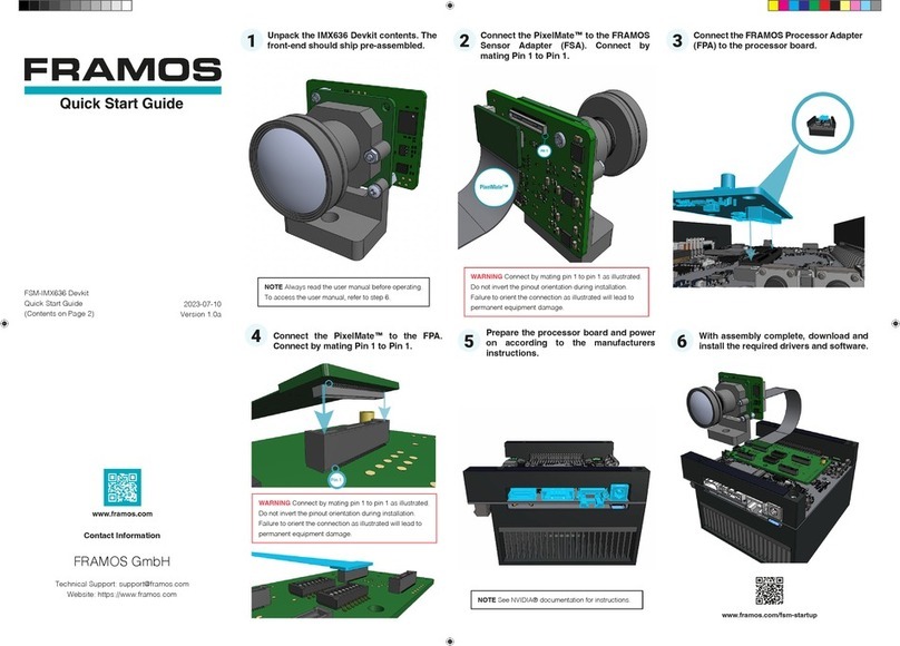
Step 1: Unpack the FRAMOS Development Kit.
Unpack the FSM-IMX636 Devkit contents. Inspect the front-end assembly referencing the illustration
below.
Figure 2. Front views of the IMX636 front-end assembly.
Figure 3. Rear views of the IMX636 front end assembly.
CAUTION If any visual damage or deviation from the illustrations below are found, approach your FRAMOS
contact and do not operate the equipment.
NOTE The front-end assembly may ship with the PixelMate™ (FMA-FC-150/60-V1A) connected. Verify the
connection is secure and pin 1 to pin 1 is aligned as indicated in the following pages.

Section
Getting Started
FSM-IMX636 Dev Kit
User Manual
July 2023
Version 1.0a 16
www.framos.com © FRAMOS 2023, information is subject to change without prior notice.
Step 2: Connect the PixelMate™to the Front End.
Connect the PixelMate™ cable (FMA-FC-150/60-V1A) to the pre-assembled front-end by carefully
aligning pin 1 to pin 1 as marked.
Figure 4. Example view of the pin 1 to pin 1 connection.
WARNING Connect by mating pin 1 to pin 1 as illustrated. Do not invert the pinout orientation during
installation. Failure to orient the cable connection as illustrated will lead to permanent equipment damage.
NOTE This step is only required if the front-end did not ship with the PixelMate™ (FMA-FC-150/60-V1A)
connected.

Section
Getting Started
FSM-IMX636 Dev Kit
User Manual
July 2023
Version 1.0a 17
www.framos.com © FRAMOS 2023, information is subject to change without prior notice.
Step 3: Connect the FPA to the Processor Board.
Connect the FPA (FPA-4.A/TXA-V1B) to the processor board.
Figure 5. Example view of the FPA to processor board connection.
NOTE If conguring up a mutliple camera setup, reference the FPA appendix pages to ensure the DIP
switch SW1 settings are correct according to your setup.
NOTE For single camera use, all DIP switch SW1 settings can be left as “OFF”. For your convenience, this
product ships with the DIP switch switch SW1 settings to “OFF”.

Section
Getting Started
FSM-IMX636 Dev Kit
User Manual
July 2023
Version 1.0a 18
www.framos.com © FRAMOS 2023, information is subject to change without prior notice.
Step 4: Connect the PixelMate™ to the FPA.
Connect the other side of the PixelMate™ (FMA-FC-150/60-V1A) cable to the FPA (FPA-4.A/TXA-
V1B) by aligning pin 1 to pin 1 as marked.
WARNING Connect by mating pin 1 to pin 1 as illustrated. Do not invert the pinout orientation during
installation. Failure to orient the cable connection as illustrated will lead to permanent equipment damage.
Figure 6. Example view of the pin 1 to pin 1 connection.
NOTE The above illustration depicts a single camera setup. Note the difference in DIP switch SW1 settings
when compared against a multiple camera setup per the data in the FPA appendix pages.
DIP Switch
SW1 on
single camera
settings

Section
Getting Started
FSM-IMX636 Dev Kit
User Manual
July 2023
Version 1.0a 19
www.framos.com © FRAMOS 2023, information is subject to change without prior notice.
Step 5: Prepare the Processor Board.
Prepare the processor board by completing the following:
Substep 1. Connect the unpowered processor board to the required peripheral devices including:
• Item 1 - Display: Connect an HDMI cable for display monitor connection
• Item 2 - USB Peripherals: Connect the HUB for input/output peripherals (keyboard, mouse) to
the processor board via the USB (2.0 or 3.0) port
• Item 3 - Network: (Optional) Using an RJ45 ethernet cable for remote development and updates
• Item 4 - Flashing: Connect the USB type-C to USB A (2.0 or 3.0) cable for processor board
ashing according to the instructions of the processor board manufacturer
Substep 2. Connect the power supply specied by the manufacturer of your processor board.
Substep 3. Follow the startup instructions of the processor board to power on.
Figure 7. Example view with callouts of the processor board setup.

Section
Getting Started
FSM-IMX636 Dev Kit
User Manual
July 2023
Version 1.0a 20
www.framos.com © FRAMOS 2023, information is subject to change without prior notice.
Figure 8. Completed assembly of the FSM-IMX636 Devkit.
Step 6: Proceed to Driver and Software Installation.
Proceed with the Driver and Software Installation instructions described in the following chapter.
Table of contents
Other FRAMOS Microcontroller manuals
Popular Microcontroller manuals by other brands

NEC
NEC 78K/0S Series user manual

Texas Instruments
Texas Instruments MSPM0G350 Series instruction manual

Atmel
Atmel SAM HA1G16A Xplained Pro user guide

GigaDevice Semiconductor
GigaDevice Semiconductor GD32E230C-START user guide

Oki
Oki MSM66591 user manual

Texas Instruments
Texas Instruments CC2520EM quick start guide