FRANCO G Max Instruction manual

INSTRUCTION MANUAL FOR
USE AND MAINTENANCE
G Max
AIR HEATER
T R A N S L AT I O N O F O R I G I N A L I N S T R U C T I O N S
ENG L I SH
C O U N T R Y O F D E S T I N AT I O N :
Read this manual carefully before
installing and operating the unit
Rev. 00/2021 Franco srl - Via Nazionale, 80 12010 Cervasca (CN)

G Max Operation and Maintenance Manual
2
INDEX
INDEX ......................................................................................................................................2
1 - INTRODUCTION.................................................................................................................3
1.1 General safety instructions .............................................................................................3
1.2 Guidelines for the correct disposal of the product...........................................................3
1.3 Conventions used in this manual....................................................................................3
1.4 Keeping and updating the instruction manual.................................................................4
1.5 Target readers................................................................................................................4
1.6 Pictograms...................................................................................................................... 5
1.7 Applications ....................................................................................................................7
1.8 Versions..........................................................................................................................7
1.9 Identification data and machine plates............................................................................7
1.10 Description of parts.......................................................................................................8
1.11 Transport and handling.................................................................................................9
1.12 Warranty.......................................................................................................................9
1.13 Manufacturer's identification data .................................................................................9
1.14 Declarations..................................................................................................................9
1.15 Declaration of conformity............................................................................................10
2 - INSTALLATION................................................................................................................ 11
2.1 Preliminary operations..................................................................................................11
2.2 Positioning.................................................................................................................... 11
2.3 Fire prevention.............................................................................................................. 13
2.5 Electrical connection.....................................................................................................13
2.6 Connection to the gas supply line................................................................................. 14
3 - OPERATION..................................................................................................................... 15
3.1 Preliminary checks........................................................................................................15
3.2 First start-up..................................................................................................................15
3.3 Start and stop ...............................................................................................................16
3.4 How to use the thermostat socket................................................................................. 17
4 - MAINTENANCE................................................................................................................ 18
4.1 Cleaning the unit...........................................................................................................18
4.2 Cleaning and replacing the nozzle................................................................................18
4.3 Accessories .................................................................................................................. 18
5 - TECHNICAL SPECIFICATIONS ...................................................................................... 19
5.1 Technical Data.............................................................................................................. 19
5.2 Spare parts list.............................................................................................................. 20
5.3 Circuit diagram..............................................................................................................23
6 - TROUBLESHOOTING GUIDE ......................................................................................... 24

G Max Operation and Maintenance Manual
3
1 - INTRODUCTION
1.1 General safety instructions
This appliance must only be used for the function for which it was designed: "Gas fired air heater". Any
other use is to be considered improper and dangerous. Franco s.r.l. cannot be held responsible for any
damage resulting from improper, incorrect and unreasonable use or if the appliance is used in systems
that do not comply with the safety regulations in force.
Check the integrity of the appliance when you open the packaging, paying particular attention to the
presence of damage or deformation that could lead to breakage and/or malfunction during use. In such
cases, do not connect the machine to the electricity and gas mains. Periodically carry out a general
check of the appliance.
Observe the safety rules indicated for electrical equipment and in particular:
•Follow the installation instructions of the appliance.
•Do not place any objects on the air heater.
•Do not allowchildren and/or incapacitated persons tooperate the unit without proper supervision;
•Do not touch the unit during operation or during the cooling phase.
•Never immerse the device in water or any other liquid.
•Do not put any objects inside the machine as this may cause irreparable damage.
•Do not use accessories, spare parts or components not specified or supplied by the
manufacturer.
•Avoid touching the device with wet or damp hands.
•Do not pull the power cords or expose them to a risk of shearing.
•Do not leave the device directly exposed to the weather (rain, sun, etc.).
•In case offailure ormalfunction, turnit off immediately and disconnect thepower andgas supply.
•Do not attempt to open or tamper with the appliance: contact a qualified technician.
1.2 Guidelines for the correct disposal of the product
Pursuant to European Directive 2012/19/EU:
At the end of its useful life, the product must not be disposed of with urban waste.
It can be delivered to the special separate waste collection centres set up by the municipal
authorities, or to retailers who provide this service. Disposing of the product separately
avoids possible negative consequences for the environment and for health deriving from
its inappropriate disposal and allows the recovery of the materials of which it is composed
in order to obtain an important saving of energy and resources. To emphasize the
obligation to dispose of electrical and electronic equipment separately, the product bears the crossed-
out wheeled bin mark.
1.3 Conventions used in this manual
The manual is divided into chapters, The type of the operator to whom the instructions are addressed
to operate the machine in safe conditions, is specified where necessary.
The sequence of chapters follows the life stages of the appliance.
To make the text easier to understand, terms, abbreviations and pictograms are used, whose meaning
is explained below :
ABBREVIATIONS
Cap.= Chapter
Par. = Paragraph
Page = Page
Fig. = Figure
Tab.= Table

G Max Operation and Maintenance Manual
4
UNIT OF MEASUREMENT
The units of measurement used are those of the International System (SI).
1.4 Keeping and updating the instruction manual
The instruction manual must be kept with care and must accompany the machine in all transfers of
ownership that it may have during its life. Parts must not be removed, torn or arbitrarily modified.
The manual should be stored in an environment protected from humidity and heat and in the immediate
vicinity of the machine to which it refers. The manufacturer, at the request of the user, can provide
additional copies of the instruction manual for the machine. For this purpose, please contact
support@francosrl.com.
The manufacturer reserves the right to modify the design and make improvements to the machine
without informing the customer, and without updating themanual already delivered to the user. However,
in the event of changes to the machine installed at the customer's premises, agreed with the
manufacturer and involving the modification of one or more chapters of the instruction manual, the
manufacturer will send the users involved the chapters affected by the change.
The user shall replace the old chapters, home page and table of contents with the new ones in all copies
owned.
The manufacturer is responsible for the original version in Italian language; in case of doubts about
the translated versions, please refer to the Italian language and contact the manufacturer
(support@francosrl.com) for support.
1.5 Target readers
This manual is intended for the installer, the operator and qualified personnel authorised to service the
machine.
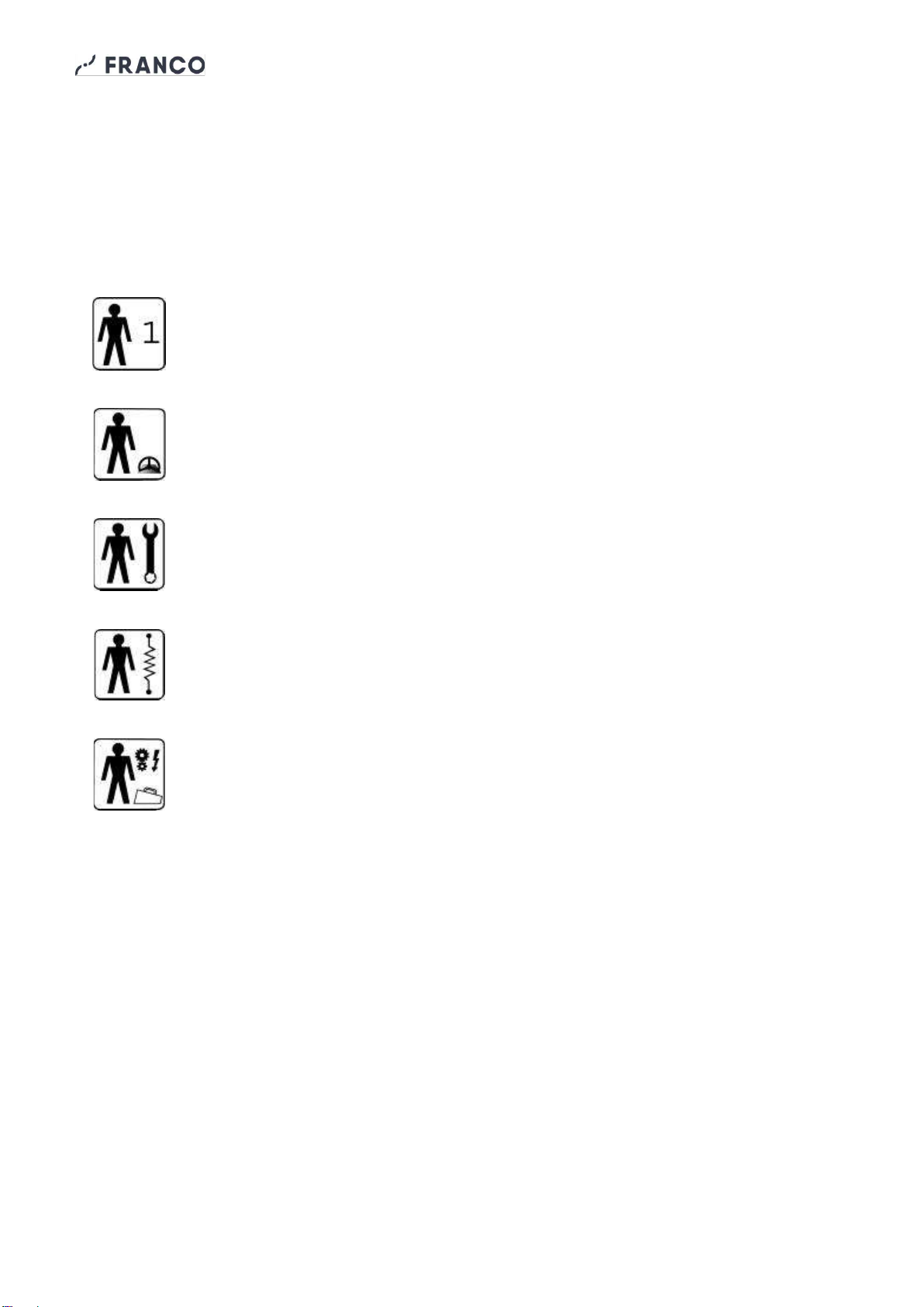
OPERATOR: means the person or persons given the task of installing, operating, adjusting, cleaning,
repairing and moving machinery and of carrying out the simplest maintenance operations;
QUALIFIED PERSONNEL / QUALIFIED WORKER: we mean those people who have followed courses
of specialization, training, etc. and have experience in installation, commissioning and maintenance,
repair, transport of the machine.
The machine is designed for industrial use, and therefore professional and not general use, therefore
its use must be entrusted to qualified figures, in particular that :
•Have reached the age of majority;
•Are physically and mentally fit to perform work of particular technical difficulty;
•Have been properly trained in the use and maintenance of the machine;
•Have been judged by the employer to be fit to perform the task assigned to them;
•Are able to understand and interpret the operator's manual and safety instructions;
•Are familiar with emergency procedures and their implementation;
•Possess the ability to operate the specific type of equipment;
•Are familiar with the specific regulations in force;
•Have understood the operating procedures defined by the machine manufacturer.
The appliance may be used by persons with reduced physical, sensory or mental capabilities, or lack of
experience or knowledge, provided that they are supervised or have received instructions concerning
the safe use of the appliance and an understanding of the hazards involved.

G Max Operation and Maintenance Manual
5
1.6 Pictograms
This section explains the meaning of the pictograms that indicate the operator's qualification, the state
of the machine, the hazards and the obligations/prohibitions to be respected. Their use makes it possible
to provide rapid and unambiguous information necessary for the correct use of the machine in safe
conditions.
PICTOGRAMS RELATING TO OPERATOR QUALIFICATION
Symbol
Description
General labourer: operator without specific skills, able to carry out only simple tasks based
on the instructions of qualified technicians.
Conductor of lifting and handling equipment: operator qualified to use equipment for
lifting and handling materials and machines (carefully following the manufacturer's
instructions), in compliance with the laws in force in the Country of destination of the
machine.
Mechanical maintenance technician: qualified technician, able to operate the machine
under normal conditions, to make it work with protections disabled, to work on mechanical
parts to make the necessary adjustments, maintenance and repairs. Typically he is not
qualified to work on live electrical systems.
Electrical maintenance technician: qualified technician, able to operate the machine under
normal conditions, to make it work with protections disabled, in charge of all eletrcial
interventions of adjustment, maintenance and repairs. He is able to operate inside live
cabinets and junction boxes.
Manufacturer's technician: a qualified technician made available by the manufacturer to
carry out operations of a complex nature in particular situations or, in any case, as agreed
with the user. The skills are, depending on the case, mechanical and/or electrical and/or
electronic and/or software.

G Max Operation and Maintenance Manual
6
SAFETY PICTOGRAMS (ISO 7010)
Pictograms contained in a triangle indicate DANGER.
Pictograms contained within a circle impose a PROHIBITION/OBBLIGATION.
Pictogram
Description
Dangerous electrical voltage
General hazard
Hot surfaces danger
Do not remove safety guards and devices
Do not clean, oil, grease, repair or adjust moving
parts by hand
Cut power before starting work or repairs
Protective gloves are mandatory
Mandatory safety footwear
Helmet is mandatory

G Max Operation and Maintenance Manual
7
1.7 Applications
The G Max air heater is a direct combustion gas appliance, specifically designed for heating premises
for agricultural and livestock use (poultry farms, greenhouses, etc.). The air is heated using the
thermal energy developed by the combustion of the gas and is then sent to the room to be heated
together with the products of combustion, thus making 100% of the thermal power produced available.
The environment must be suitably ventilated in order to ensure air renewal and emission control.
Do not use theheater in basements or below ground level, nor in rooms used for domestic purposes.
The appliance is equipped with all the safety devices required by regulations, ensuring safe operation
in all conditions.
- Flame control device: it performs pre-ignition checks, controls the ignition sequence, checks the
presence of flame during operation and locks the machine out in case of anomalies.
- Safety thermostat with manual reset: protects the appliance from overheating by switching off
the burner.
- Air flow switch: it functions in case of an abnormal reduction of the air flow, causing the flame to
extinguish.
The materials and components used guarantee high reliability, corrosion resistance and durability even
in the most critical environments.
This machine should only be used for the purpose
for which it was designed:
"Gas-fired air heater for space heating
for agricultural and livestock use".
All other uses are considered improper and potentially dangerous.
1.8 Versions
The G Maxheater is available in the following version:
4208000 G Max 70 70 kW 3000 m³/h 230V~ 50Hz
1.9 Identification data and machine plates
Each machine is identified by a CE plate on which the reference data are indelibly marked. For any communication
with the manufacturer or service, always quote these references (Fig. 1.9.1).
Fig.1.9.1

G Max Operation and Maintenance Manual
8
1.10 Description of parts
Main parts of the air heater:
Electrical panel
Fig.1.3
Fan
Safety thermostat
Sensing/ignition
electrodes
Nozzle
Handling
brackets
Burner reset button
Room thermostat
socket
Pipe connection
power supply
gas ½" M
Schuko plug
CEE 7/4
Thermostat socket cap
with jumper
(see paragraph 2.3)
Air flow switch
Burner
Fixing brackets
Fixing brackets

G Max Operation and Maintenance Manual
9
1.11 Transport and handling
The machine is properly packed in sturdy cardboard boxes.
Be careful when opening the packaging to prevent damaging the unit. Check the integrity of
the machine making sure that there are no visibly damaged parts.
Do not dispose of the packaging elements in the environment: they must be stored in
appropriate collection points.
The G Max heater can be lifted and suspended using the appropriate fixing and handling
brackets.
ATTENTION!
Before moving the unit:
a. stop the machine,
b. switch off the power supply,
c. cut the gas supply,
d. wait for the heater to cool down.
Use suitable lifting gear to move the machine. The weight is indicated on the nameplate and in the
manual at par. 5.1 "Technical data". Carry out the operations with caution, using the appropriate
personal protective equipment, making sure that the machine is not subject to shocks or falls, and
positioning the lifting belts correctly.
1.12 Warranty
This product is guaranteed for 12 months from the date of manufacture for all faults attributable to a
proven manufacturing or material defect. The warranty does not cover all parts damaged by transport,
bad or incorrect maintenance, neglect, inability to use, improper use, tampering by unauthorized
personnel and in any case from causes not dependent on Franco s.r.l. - Cervasca (CN). During the
warranty period, Franco s.r.l. undertakes to provide free of charge those parts that may be defective at
the origin.
Any repair work must be carried out by a qualified technician authorized by Franco s.r.l.
1.13 Manufacturer's identification data
Manufacturer
FRANCO s.r.l.
Legal and administrative headquarters
VIA NAZIONALE, 80 - 12010 CERVASCA (CN) - ITALY
Contact
Tel.: (0039) 0171 - 61.16.63
Email: support@francosrl.com
Web: www.francosrl.com
1.14 Declarations
The machine is manufactured in compliance with the relevant European Directives applicable at the
time of its placing on the market.
The machine is not included among those listed in All. IV of Directive 2006/42/EC.

G Max Operation and Maintenance Manual
10
1.15 Declaration of conformity
(Annex IIa Directive 2006/42/EC)
THE MANUFACTURER
FRANCO s.r.l.
Company
Via Nazionale, 80 12010 CN
Address Cap Province
Cervasca Italy
City State
DECLARES under its own responsibility that the machine:
Gas fired air heater G Max 70
Description Model
4208000
Series/Matrix
G Max 70 Gas fired air heater
Trade name
Heating of agricultural and livestock premises
Intended use complies with the following European Directives:
2006/42/EC Machinery Directive
EU 2016/426 Gas Appliances Regulation, Cert. n° CE51CS4822 issued by IMQ
(2014/35/EU) (Low Voltage Directive)
2014/30/EU Electromagnetic Compatibility Directive
Harmonized standards and reference specifications used:
EN 12100:2010
EN 525:2009
EN 60335-1:2012 + A11:2014 + A13:2017
EN 60335-2-102:2016
EN 61000-3:2013, EN 55014-1:2017, EN 55014-2:2015
Legal entity authorized to establish the Technical File:
FRANCO s.r.l.
Name
Via Nazionale, 80 12010 CN
Address Cap Province
Cervasca Italy
City State
Place and date of document
The manufacturer
Cervasca, 10/12/2021
Signature
Rev. 00/2021
Marco Fantino
Administrator

G Max Operation and Maintenance Manual
11
2 - INSTALLATION
2.1 Preliminary operations
To operate the G Max heater, you need:
•electrical network with voltage and frequency characteristics suitable for the
machine, with earth connection and protection devices;
•gas supply line with specifications suitable for the machine
Before installing the unit, make sure that:
- the local distribution conditions, the type of gas and the supply pressure are compatible
with the current setting of the appliance.
- the local power supply conditions are compatible with the electrical characteristics of the appliance,
shown on the data plate on the side of the appliance (see par. 1.9).
2.2 Positioning
The G Max air heater must be installed in a vertical position, outside, as shown in Fig.
2.2.1 and 2.2.2.
The following parts are supplied with the unit:
- 2 air inlet/outlet ducts, complete with protection grids, fixing screws and closing panels, to be
installed to recirculate the air from the heated space or to draw it in from outside.
- 4 brackets with fastening elements for wall installation (recommended option). If installation in
contact with the wall is not possible (e.g. to meet legal requirements), the unit can be placed at
a distance from the wall on a suitable support structure.
The guidelines provided are purely indicative: the optimal position of the air heater in relation to the
room to be heated must be chosen by the designer of the system or in any case by a qualified person,
considering both the technical aspects and the laws in force (e.g. fire prevention regulations, see par.
2.3) and, if necessary, requestingthe necessary authorisations. In any case, the following requirements
must be complied with:
•Any gas cylinders must be used and stored in accordance with the regulations in force.
•Accessibility for maintenance and inspection operations must always be ensured.
•Appropriate continuous ventilation must be provided in the heated room (see also par.
2.4).
•It is forbidden to install the machine near flammable/combustible materials (see also par.
2.3).
•It is forbidden to deposit any material in a range of 2 m from the hot air outlet.
•It is forbidden to connect air ducts to the hot air outlet.
•It is forbidden to modify the inlet and outlet sections of the machine.
•It is forbidden to install the machine in environments with flammable or explosive
atmosphere.
•It is forbidden to install the machine in areas where dust, leaves, dirt, etc. may obstruct
the heater inlet and outlet and thus reduce the airflow.
•The machine must be used within the ambient temperature and humidity range shown in
the technical data table.

G Max Operation and Maintenance Manual
12
Fig. 2.2.1 - Connecting inlet and outlet ducts
Fig. 2.2.2 - Wall installation with air recirculation or external suction
n.20 self-tapping
screws
hexagonal head
flanged 4.2x13
Bracket
Washer
Grower
Washer
Screw
M8
Bracket
Flat
Washer
Grower
Washer
Screw
M8
OUTDOOR
INDOOR
OUTDOOR
INDOOR

G Max Operation and Maintenance Manual
13
EXAMPLE OF INSTALLATION IN A ZOOTECHNICAL PREMISE
2.3 Fire prevention
The G Max heater must be installed in compliance with the fire prevention legislation in
force in the Country of destination. Make sure you follow all the local and national rules
and laws in force in the Country of destination, contacting the relevant authorities for
assistance (fire department, etc.) and getting the required authorizations if necessary.
2.4 Ventilation requirements
The G Max is a direct fired heater, which releases hot air mixed with the products of combustion into
the heated space. It is therefore necessary, in order to keep the emissions within safety limits, to ensure
an appropriate renewal of the air in the room. According to European guidelines (e.g. EN 525:2009,
Annex C), the whole of the appliances installed (air heaters, fans, etc.) must be sized so that the volume
concentration of carbon dioxide (CO2) inthe environment does not exceed 0.28% (2800ppm), especially
in areas where people may be present.
The following table shows the theoretical values of the fresh air flow rate to be introduced into the
environment according to the installed thermal power, in order to maintain a CO2 concentration < 0.28%
for the most commonly used gases.
G20
(methane)
G30
(butane)
G31
(propane)
Minimum fresh air flow per
kW of installed heating
power (m3/h)/kW
37,8
47,3
45,7
Fresh air flow rate for each
unit G Max installed (m3/h)
2650
3300
3200
2.5 Electrical connections
The G Max heater is equipped with a Schuko cable and plug for connection to a 230V
50Hz single-phase earthed electric system. The heater is preset for operation with a
room thermostat which, when connected to the thermostat socket, automatically starts
and stops themachine accordingto the set temperature. Alternatively, an external On/Off
switch can be provided for manual operation (see par.1.10).
•The electrical connection must be carried out by recognised and authorised
technicians in accordance with the regulations in force.
•Ensure that the power supply ratings are as shown on the dataplate and in the
manual.
•It is mandatory to connect the equipment to an efficient earthing line.
ASPIRATION
MANDATORY
The height must be compatible
with the type of breeding/cultivation

G Max Operation and Maintenance Manual
14
In any case, a device for disconnecting the appliance from the power supply should be provided.
2.6 Connection to the gas supply line
The G Max heater is designed for connection to a gas supply line through a ½"
threaded connection located on the side of the electrical box.
•Check that the type of gas supplied and the supply pressure are those prescribed
on the appliance's data plate and in the technical data table (see par. 2.6).
•Connect the appliance to the supply line, providing a manual shut-off valve and, if
necessary, a pressure regulator (parts not supplied).
•Only use an approved flexible hose with a maximum length of 2 m for the
connection and make sure it is free of restrictions. Do not use metal tubing for
the connection to the heater.
•The gas supply line must comply with the relevant regulations in force.
N.B.: When connecting the gas hose, hold the lock nut on the side of the electrical
box with a spanner while tightening the nut on the hose to avoid excessive torsional
stress on the internal fittings and compromise their soundness.
1 –Room thermostat line 2x1.5mm 2
2 - Heater power supply line 3x1,5mm 2
3 - Gas supply line (from line
main valve) 1/2"
4 - Shut-off valve 1/2"
(5 - Pressure Regulator, if needed)
6 - 1/2" flexible gas hose
7 - Thermostat socket

G Max Operation and Maintenance Manual
15
3 - OPERATION
3.1 Preliminary checks
Before starting the heater, check that:
1. All connections, both electrical and gas, are made according to the instructions in this manual;
2. The heater is free and clean;
3. The manual gas shut-off valve on the gas supply line is open.
3.2 First start-up
•The operations described in this paragraph must be carried out exclusively by authorised
and qualified technical personnel, using suitable personal protective equipment.
•Check that the air inlet and outlet sections are not obstructed, even partially;
•Make sure that all cables are properly positioned and that they are not pinched or
pulled too tight;
•Ensure that the connections to the gas supply line are correct;
•Open the tap on the gas supply line (or cylinder)
•Check that there are no leaks along the gas supply line and on the connections
using a leak detector liquid or soapy water.
•Check that the supply pressure complies with what is shown in the technical data
tables for the type of gas used.
•Start the heater by setting the room thermostat to the desired temperature, or, in the case of
manual operation, by powering up the appliance via an ON/OFF switch, electrical
panel, etc.
•Check that the startup sequence is correct.
Startup sequence
The contact on pins 1-2 of the thermostat socket
is closed
KO →
Wait for contact closure
OK
Gas valve test (3")
KO →
Lock-out + light signal
OK
Flow switch test: contact open?
KO →
Wait until it opens
OK
Fan start
Flow switch test: contact closed (4")?
KO →
Lock-out + light signal
OK
Check closure (3")
“No flame”check
KO →
Lock-out + light signal
OK
Opening gas valve and spark
“Flame on” check
KO →
Lock-out + light signal
OK
Flame on: regular operation
Control and adjustment of working pressures
The unit is equipped with a multifunctional gas valve that includes two safety solenoid valves and a
regulator, allowing to control the inlet and outlet gas pressures and to adjust the outlet pressure to the
burner (see Fig. 3.2.1)
The appliance is set at the factory for operation in the Country of destination, with the type of gas and
pressure shown on the setting data label on the side of the appliance.

G Max Operation and Maintenance Manual
16
To check the inlet and outlet pressures, with the appliance in operation, access the gas valve inside
the electrical box and carry out the following operations:
•Unscrew the closing screw from the "PIN" socket
(ref. A), connect a differential manometer to the
socket and check the inlet pressure
•Unscrew the closing screw from the "POUT" socket
(ref. B), connect adifferential manometer andcheck
the outlet pressure
If the pressures are correct (see setting data table), seal
the adjusting screws.
To adjust the outlet pressure:
•Remove the threaded protection cap (C)
•Turn the internal adjustment screw (D) clockwise
using a fine blade screwdriver (5.5x0.8) to increase
the outlet pressure and counterclockwise to
decrease the outlet pressure.
•Once the pressure has been adjusted, seal the adjustment screw and reinsert the threaded plug
(C).
SETTING DATA TABLE
Country of
destination
Category
Type of gas
Supply
pressure
(mbar)
Burner
pressure
(mbar)
Nozzle
diameter
(mm)
GB
II 2H3+
G20
20
16,5
6,5
G30/G31
28-30/37
23,0
4,1
3.3 Start and stop
Start
To start the heater, set the room thermostat to thedesired temperature, or, with manualoperation, power
up the appliance by turning the switch, provided in the electrical system, to ON.
During operation
- In case of abnormal reduction of the air flow, the flow switch contact opens, the machine stops
and the signal light turns on.
- In the event of flame failure or combustion anomalies, the machine makes three attempts to re-
ignite. If the flame does not re-ignite, the machinestops and the lockout warning light illuminates.
- In the event of abnormal overheating of the appliance, the safety thermostat intervenes by
switching off the burner.
- When the desired temperature is reached in the room, the contact on the thermostat socket
opens and the heater stops without signalling. The appliance restarts automatically performing
the start-up sequence when the temperature drops and the contact closes again.
If the appliance locks out
•Find and remove the cause of the lock-out (poor ventilation, flame failure, etc.). If needed,
contact qualified personnel.
•Press and hold the reset button for at least 3 seconds. The indicator light will go out and the
start-up sequence will be repeated. If the unit continues to lock-out, turn it off and contact
technical service.
A
B
C
D
Fig. 3.2.1

G Max Operation and Maintenance Manual
17
If the safety thermostat trips on
•Switch off the power, turn off the gas and wait for the
appliance to cool down completely.
•Find and remove the cause of overheating. If necessary,
contact qualified personnel.
•Open the inspection door and use a screwdriver to press the
reset button on the safety thermostat inside the connector
until you hear a "click" (see Fig. 3.3.1). If the appliance does
not restart, or the safety thermostat continues to trip, switch it
off and contact technical service.
Fig. 3.4.1
ATTENTION!
The unit delivers a high temperature air flow. Do not place any flammable objects
or materials within 2 m of the air outlet. During normal operation, and for some
time after shutdown, some parts of the machine can reach very high
temperatures! Always use suitable personal protective equipment.
Stop
•Operation with a thermostat: the heater stops automatically when the desired
temperature is reached. Manual operation: cut off the power to the heater by turning
the switch, if fitted in the system, to the OFF position.
Seasonal use
G Max heaters are mainly intended for seasonal use. At the end of the winter season, or in general if
the appliance is not used for long periods:
- Disconnect the appliance from mains and close the gas supply valve.
- Thoroughly clean both the external surfaces and the internal parts (fan, burner, etc. see also
Par. 4.1 and 4.2).
- Close the air inlet and outlet vents with the sliding panels provided with the unit.
- If necessary, cover the heater with a protective sheet to protect it from the weather.
- At the beginning of the next winter season, before using the appliance again: remove the cover,
the closing panels, restore the electrical and gas connections and carry outa complete functional
check of the machine.
3.4 How to use the thermostat socket
The G Max heater is equipped with a socket located on the side of the electrical
box for connecting an external switching device (room thermostat, timer,
control unit, etc.).
For the remote control of burner ignition and shutdown, connect the device to
terminals 1 and 2 of the thermostat plug, supplied.
For manual operation, connect an On/Off switch to the power supply line of the
appliance and insert the cap with internal jumper between terminals 1 and 2,
supplied with the unit, into the thermostat socket.
CLICK!
Fig. 5.4.1

G Max Operation and Maintenance Manual
18
4 - MAINTENANCE
•The operations described in this chapter must only be carried out by authorised and qualified
personnel, using suitable personal protective equipment.
•Before starting any work on the heater: switch off power, close the main gas valve and make
sure that the machine has completely cooled down.
4.1 Cleaning the unit
Clean the external surfaces regularly, with appropriate frequency depending on the conditions of use,
and in particular the air inlet and outlet ducts and grills, which must always be perfectly free of any
obstructions.
Open the inspection door and regularly clean the machine body, the fan, the internal surfaces and
components with a soft dampened cloth and a non-toxic solvent-free cleaning agent, wiping carefully
and, if necessary, using compressed air to remove dust and dirt deposits.
Do not direct water jets, even indirectly, at the motor, burner or electrical parts. Periodically check the
tightness of screws and bolts, especially in the presence of unusual noises and vibrations.
4.2 Cleaning and replacing the nozzle
Open the inspection door, unscrew the nozzle from the nozzle holder
using a 13 mm hexagonal wrench (Fig. 4.1.1, take care, it could
accidentally fall into the burner tube). Check and clean the nozzle
using compressed air and make sure that the internal hole is perfectly
free of impurities. If necessary, replace the nozzle with one of the
same diameter. Refit the nozzle, close the door and check operation. If
you need to operate the heater with a different gas type (e.g. from
methane to propane/butane) it is necessary to replace the nozzle
and adjust the outlet pressure of the gas valve referring to the
setting data table (see Par. 3.2).
NOZZLE SPECIFICATIONS
G30/G31
28-30/37 mbar
G20
20 mbar
Code
8101502 (L410)
8101552 (L650)
Ø mm
4,10
6,50
4.3 Accessories
A complete range of accessories such as electronic thermostats, brackets, air delivery baffles, etc. is
available for your G Max.
Ask your dealer for a catalogue to get more information about accessories.
Nozzle
Nozzle
holder
Venturi
tube
Fig. 4.1.1

G Max Operation and Maintenance Manual
19
5 - TECHNICAL SPECIFICATIONS
5.1 Technical Data
Overall dimensions
TECHNICAL DATA
G Max
Thermal power (Hs)
kW
kcal/h
70
60200
Air flow rate
*on inlet section
m3/h
3000*
Gas consumption
@1013mbar/15°C
G20 (methane)
G30/G31 (propane/butane)
m3/h
kg/h
6,67
5,07
Gas pressure
G20 (methane)
G30/G31 (propane/butane)
mbar
mbar
20
28-30/37
Nozzle diameter
G20 (methane)
G30/G31 (propane/butane)
mm
mm
6,5
4,1
Voltage
V/Hz
230/50
Power consumption
W
610
Current consumption
A
2,8
Noise
dB(A)
71
Operating conditions
Temperature range
Relative humidity
°C
%
-15/+35
95 max
Weight
kg
70

G Max Operation and Maintenance Manual
20
5.2 Spare parts list
Use only original spare parts.
Orders should be placed specifying at least the following:
- Appliance model/Mfg. year
- Spare part number
- Quantity
- Shipping address
HEATER ASSEMBLY
Table of contents
Other FRANCO Heater manuals
Popular Heater manuals by other brands

Sealey
Sealey IR28 instructions

flowair
flowair ELIS DUO-W-100 Technical documentation operation manual

Gabarron
Gabarron ADL 5030/14 Installation instructions and user guide

Zobo
Zobo ZB-K45 User's manual and operating instructions

Tylo
Tylo SU 2/4 Instructions for installation and use

ARDES
ARDES AR454B Instructions for use