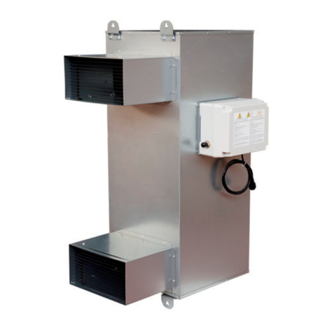
FRANCO AP Max 50 Instruction manual

INSTRUCTION MANUAL FOR
USE AND MAINTENANCE
AP Max
HOT WATER
AIR HEATER
T R A N S L AT I O N O F O R I G I N A L I N S T R U C T I O N S
ENG L I SH
It is mandatory to read this manual carefully before
install or perform operations on the machine.
Manual version: 00/2022 Franco srl - Via Nazionale, 80 - 12010 Cervasca (CN)

FRANCO s. r. l. Instruction Manual - AP Max
2
INDEX
INDEX......................................................................................................................................2
1 - INTRODUCTION.................................................................................................................3
1.1 General Warnings...........................................................................................................3
1.2 Guidelines for the proper disposal of the product ...........................................................3
1.3 Conventions used in this manual....................................................................................3
1.4 Keeping and updating the instruction manual.................................................................4
1.5 Addressees.....................................................................................................................4
1.6 Pictograms......................................................................................................................4
1.7 Applications ....................................................................................................................7
1.8 Versions..........................................................................................................................7
1.9 Machine identification data and plates............................................................................7
1.10 Description of Parts ......................................................................................................8
..............................................................................................................................................8
1.11 Transport and handling................................................................................................. 9
1.12 Warranty.......................................................................................................................9
1.13 Manufacturer's identification data .................................................................................9
1.14 Declarations..................................................................................................................9
1.15 Declaration of Conformity ...........................................................................................10
2 - INSTALLATION.................................................................................................................11
2.1 Preliminary Operations .................................................................................................11
2.2 Positioning....................................................................................................................11
2.3 Assembly diagrams ......................................................................................................13
2.4 Electrical Connection.................................................................................................... 17
2.5 Hydraulic connection .................................................................................................... 17
3 - OPERATION.....................................................................................................................17
3.1 Preliminary Operations .................................................................................................17
3.2 First Start-up................................................................................................................. 17
3.3 Start-up.........................................................................................................................17
4 - MAINTENANCE................................................................................................................18
4.1 Cleaning the machine...................................................................................................18
4.2 Replacing the fan..........................................................................................................18
4.3 Replacing the exchanger.............................................................................................. 18
4.4 Accessories .................................................................................................................. 18
5 - TECHNICAL CHARACTERISTICS................................................................................... 20
5.1 Technical Data.............................................................................................................. 20
5.2 Spare parts list.............................................................................................................. 22
5.3 Circuit diagrams............................................................................................................ 23
6 - PROBLEM-SOLVING GUIDE...........................................................................................23

FRANCO s. r. l. Instruction Manual - AP Max
3
1 - INTRODUCTION
1.1 General Warnings
This appliance may only be used for the function for which it was expressly designed "Hot water air
heater". Any other use is considered improper and dangerous.
Franco s.r.l. cannot be held liable for any damage resulting from improper, incorrect and unreasonable
use or if the device is used in installations that do not comply with current safety regulations.
- Check the integrity of the machine when opening the packaging, paying particular attention to the
presence of damage or deformation that could lead to breakage and/or malfunction during use. In such
cases, do not connect the machine to the electrical and hydraulic mains. Carry out these checks before
each use.
- Before connecting the appliance, make sure that the rating plate data correspond to those of your
electrical distribution network. The data label is located on the side of the appliance (see section 1.9).
- Observe the safety regulations indicated for electrical equipment and in particular:
oFollow the installation instructions of the appliance.
oDo not place objects on the unit heater.
oPrevent children and/or incapacitated persons from using the device without proper supervision;
oDo not touch the unit heater during operation or during the cooling phase of the heat exchanger;
oNever immerse the appliance in water or any other liquid. Do not touch the appliance if it
accidentally gets wet: switch off the power supply before touching the appliance.
oDo not put any objects inside the machine as it could be irreparably damaged.
oDo not use accessories, spare parts and/or components not specified/supplied by the
manufacturer.
oAvoid touching the device with wet and/or damp hands.
oDo not pull on the power cable or expose to risk of shearing.
oDo not leave the device exposed to the weather (rain, sun, etc.).
oIn the event of a fault and/or malfunction of the appliance, switch it off immediately and
disconnect the power supply
oDo not attempt to open or tamper with the unit: contact a qualified technician.
1.2 Guidelines for the proper disposal of the product
Pursuant to European Directive 2012/19/EU:
At the end of its useful life, the product must not be disposed of with municipal waste.
It can be handed in at the special separate waste collection centres set up by
municipalities, or at retailers who provide this service. Disposing of the product
separately avoids possible negative consequences for the environment and health
resulting from inappropriate disposal, and allows the materials of which it is composed
to be recovered in order to achieve significant savings in energy and resources. To
emphasise the obligation to dispose of electrical and electronic equipment separately,
the product is marked with a crossed-out wheeled bin.
1.3 Conventions used in this manual
The manual is divided into chapters, within which the operators to whom the instructions are addressed
are specified, where necessary, in order to operate the machine safely.
The sequence of chapters responds to the temporal logic of the machine's life.
To facilitate immediate understanding of the text, terms, abbreviations and pictograms are used, the
meaning of which is indicated below.
ABBREVIATIONS
Cap. = Chapter
Par. = Paragraph

FRANCO s. r. l. Instruction Manual - AP Max
4
Page = Page
Fig. = Figure
Tab. = Table
UNIT OF MEASUREMENT
The units of measurement used are those of the International System (SI).
1.4 Keeping and updating the instruction manual
The instruction manual must be kept with care and must accompany the machine in all changes of
ownership that it may undergo during its life. Parts must not be removed, torn off or arbitrarily modified.
The manual should be stored in an environment protected from moisture and heat and in the immediate
vicinity of the machine to which it refers. The manufacturer can provide additional copies of the machine
instruction manual at the user's request. You can request this by writing to support@francosrl.com.
The manufacturer reserves the right to modify the design and make improvements to the machine
without informing the customer, and without updating themanual alreadydelivered to the user. However,
in the event of changes to the machine installed at the customer's premises, agreed with the
manufacturer and involving the modification of one or more chapters of the instruction manual, it will be
the manufacturer's responsibility to send the affected users the chapters affected by the change.
It is the responsibility of the user to replace the old chapters, homepage and table of contents with the
new ones in all copies owned.
The manufacturer is responsible for the original Italian language version; in case of doubts regarding
the translated versions, please refer to the Italian language and contact the manufacturer
(support@francosrl.com) for verification.
1.5 Addressees
This manual is intended for the installer, operator and qualified personnel authorised to service the
machine.
OPERATOR: means the person(s) in charge of installing, operating, adjusting, cleaning, repairing and
moving a machine and performing the simplest maintenance operations;
QUALIFIED PERSONNEL/QUALIFIED WORKMAN: this refers to those persons who have attended
specialisation courses, training, etc. and have experience in the installation, commissioning and
maintenance, repair, transport of the machine.
The machine is intended for industrial use, and therefore professional and not general use, so its use
must be entrusted to qualified persons, in particular who
•have reached the age of majority;
•They are physically and mentally fit to perform work of particular technical difficulty;
•Have been properly instructed in the use and maintenance of the machine;
•They were judged by their employer to be fit to perform the task entrusted to them;
•Be able to understand and interpret the operator's manual and safety instructions;
•They are familiar with emergency procedures and their implementation;
•Possess the ability to operate the specific type of equipment;
•Be familiar with the specific rules of the case;
•Have understood the operating procedures defined by the machine manufacturer.
The appliance may be used by persons with reduced physical, sensory or mental capabilities, or lack of
experience or the necessary knowledge, provided that they are supervised or have received instructions
concerning the safe use of the appliance and understanding of the dangers involved.
1.6 Pictograms
This section explains the meaning of the pictograms indicating the operator's qualification, the state of
the machine, the hazards and the obligations/prohibitions to be observed. Their use makes it possible

FRANCO s. r. l. Instruction Manual - AP Max
5
to quickly and unambiguously provide the information necessary for the correct use of the machine in
safe conditions.
PICTOGRAMS RELATING TO OPERATOR QUALIFICATION
Symbol
Description
General labourer: an operator without specific skills, capable of carrying out only simple
tasks on the instructions of qualified technicians.
Driver of lifting and handling equipment: an operator qualified to use lifting and handling
equipment and machines (strictly in accordance with the manufacturer's instructions), in
accordance with the laws in force in the country of the machine user.
Mechanical maintenance technician: a qualified technician, capable of operating the
machine under normal conditions, operating it with protections disabled, working on
mechanical parts to carry out the necessary adjustments, maintenance and repairs.
Typically, he is not qualified to work on electrical systems where voltage is present.
Electrical maintenance technician: qualified technician, able to operate the machine under
normal conditions, to operate it with protections disabled, is in charge of all electrical
adjustment, maintenance and repair work. He is able to work in the presence of voltage
inside cabinets and distribution boards.
Manufacturer's technician: qualified technician made available by the manufacturer to carry
out operations of a complex nature in particular situations or, in any case, as agreed with
the user. The skills are, depending on the case, mechanical and/or electrical and/or
electronic and/or software.
SAFETY PICTOGRAMS (ISO 7010)
The pictograms contained in a triangle indicate DANGER.

FRANCO s. r. l. Instruction Manual - AP Max
6
The pictograms contained in a circle impose a PROHIBITION/OBLIGATION.
Pictogram
Description
Dangerous electrical voltage
General danger
Danger hot surfaces
Do not remove safety devices
Prohibition of cleaning, oiling, greasing, repairing
or adjusting moving parts by hand
Obligation to cut power before starting work or
repairs
Mandatory protective gloves
Compulsory safety footwear
Mandatory safety helmet

FRANCO s. r. l. Instruction Manual - AP Max
7
1.7 Applications
The AP Max unit heaters are used in the industrial sector, inside rooms where you want to raise the
temperature, having hot process or central heating water available.
They can also be used inside shopping centres, workshops, showrooms, gyms, dairies, etc.
In the livestock sector they can be used in chicken farms, in tunnels with longitudinal, natural and
chimney ventilation. In agriculture they are used for heating or cooling greenhouses and mushroom
farms. Installed with vertical air flow, they allow heat destratification.
The materials used guarantee reliability and durability.
The exchanger is constructed with coppertubes and aluminium fins with increased pitch and thickness,
painted with cataphoresis, a treatment that gives it a high resistance to corrosion.
The structure of the hot water air heater is made of polypropylene, a material with low specific weight
and high chemical and mechanical resistance.
The fans used on the AP Max series are axial 6-pole single-phase (with pre-wired condenser) or three-
phase, with IP 54 protection. The motors have class F insulation and are equipped with thermal
protection with automatic reset. All hardware is stainless steel.
This machine must only be used for the purpose
for which it was designed:
- Water heating.
All other uses are to be considered improper and therefore dangerous.
1.8 Versions
The AP Max series unit heaters are available in the following versions:
2458000 Version AP Max 50 power 50 kW - 6,500 m³/h 230 V 1~ 50 Hz
2458010 Version AP Max 80 power 80 kW - 6,500 m³/h 230 V 1~ 50 Hz
2458002 Version AP Max 50 power 50 kW - 6,500 m³/h 400 V 3~ 50 Hz
2458012 Version AP Max 80 power 80 kW - 6,500 m³/h 400 V 3~ 50 Hz
1.9 Machine identification data and plates
Each machine is identified by a CE plate on which the machine's reference data is indelibly marked. For
any communication with the manufacturer or service centres, always quote these references.
Fig.1.9.1

FRANCO s. r. l. Instruction Manual - AP Max
8
1.10 Description of Parts
Fig.1.10.1
Delivery connection
water
Heater body
Protection grid
Fan
Water return
connection
Exchanger
Quick-closing
system
Air distributor
Height adjustment
distributor
Data label
Exchanger

FRANCO s. r. l. Instruction Manual - AP Max
9
1.11 Transport and handling
The machine is properly packed before being
placed in sturdy cardboard containers. Avoid
damage to machine components by taking
great care when opening the packaging.
Check the integrity of the machine by checking that there are no visibly damaged parts.
Do not dispose of packaging elements in the environment, they should be placed in appropriate
collection places.
The AP Max can be lifted and suspended using the appropriate brackets.
WARNING!
Before moving the device you must:
a. stop the machine,
b. switch off the power supply,
c. cut off the water supply,
d. Wait for the heat exchanger to cool down.
To lift the machine, use suitable lifting gear (see weight table).
Lift it slowly, taking care that it does not fall, and move the straps according to the centre of gravity.
1.12 Warranty
This appliance is guaranteed for 12 months from the date of manufacture for all faults attributed to a
proven manufacturing or material defect. The warranty does not cover all parts damaged by transport,
bad or incorrect maintenance, neglect, incapacity for use, improper use, tampering by unauthorised
personnel and in any case by causes beyond the control of Franco s.r.l. of Cervasca (CN). During the
warranty period, Franco s.r.l. undertakes to replace or repair, free of charge, those parts which prove to
be defective at source.
The intervention must be carried out at Franco s.r.l. with transport paid for by the user.
1.13 Manufacturer's identification data
Manufacturer
FRANCO S.r.l.
Legal - administrative headquarters
VIA NAZIONALE, 80 - 12010 CERVASCA (CN) - ITALY
Contact
Tel.: (0039) 0171 - 61.16.63
Email: [email protected]
Web: www.francosrl.com
1.14 Declarations
The machine is manufactured in accordance with the relevant Community Directives applicable at the
time of its placing on the market.
The machine is not among those mentioned in All. IV of Directive 2006/42/EC.

FRANCO s. r. l. Instruction Manual - AP Max
10
1.15 Declaration of Conformity
(Annex IIa Dir. 2006/42/EC)
THE MANUFACTURER
FRANCO s.r.l.
Company
Via Nazionale, 80 12010 CN
Address Postcode Province
Cervasca Italy
City State
STATES THAT THE MACHINE
Water heater AP Max 50 / AP Max 80
Description Model
2458000 / 2458002 / 2458010 / 2458012
Code
AP Max Water heater
Trade name
Space heating or cooling
Intended use
complies with the following European Directives:
2006/42/EC Machinery Directive
(2014/35/EU) (Low Voltage Directive)
2014/30/EU Electromagnetic Compatibility Directive
Harmonised standards and reference specifications used:
EN 12100:2010
EN 60335-1:2012 + A11:2014 + A13:2017
EN 61000-3:2013, EN 55014-1:2017, EN 55014-2:2015
Legal person authorised to set up the Technical File:
FRANCO s.r.l.
Name
Via Nazionale, 80 12010 CN
Address POSTCODE Province
Cervasca Italy
City State
Place and date of document
The manufacturer
Cervasca, 02/05/2022
Signature
Rev. 00/2022
Marco Fantino
Administrator

FRANCO s. r. l. Instruction Manual - AP Max
11
2 - INSTALLATION
2.1 Preliminary Operations
For the AP Max hot water air heater to beoperational, it is necessary tohave:
- mains with voltage and frequency characteristics suitable for the machine
with earth and protective devices;
- Connection to a hot / cold water production system;
- Condensate water drainage connection.
The installation must fulfil the requirements
safety regulations in force in the country of destination of the device.
Therefore, make sure that all connections necessary to operate the appliance have been correctly set
up.
2.2 Positioning
The AP Max unit is a unit for pendant installation. The unit can be installed horizontally, free-flowing, or
vertically downwards with the diffuser plate.
Depending on the type of installation, assemble and fasten thespecial brackets supplied as accessories
to the unit, by means of which the unit heater can be suspended using suitably dimensioned holding
means (chains, wire ropes, etc.). The centre distances of the eyebolts/fixing holes are shown in Fig.
2.2.1.
Ensure that the means of attachment and the structure from which the unit will be suspended
are able to withstand the relevant stresses (own weight, vibrations) If necessary, contact
qualified personnel for verification.
Bracket for horizontal suspension
Bracket for vertical suspension
Fig. 2.2.1 - Position of holes for suspension/staffing

FRANCO s. r. l. Instruction Manual - AP Max
12
The AP Max must be positioned in such a way as to allow optimal intake and distribution of
air in the served space and the performance of necessary maintenance work. In heating
mode, the AP Max generates a high temperature air flow.
•Do not deposit any combustible material or objects within 3 m of the heater.
•It is also advisable to maintain the following minimum distances between the device and
walls/ceilings:
- Minimum distance from the ceiling: 1 m
- Minimum distance from wall (or ceiling) - suction side: 0.6 m
- Minimum distance from side walls: 1 m
- Minimum distance from wall - discharge side: 3 m
WARNING!
•The installation must ensure compliance with the requirements of standard UNI EN
ISO 13857:2008 with regard to protection against accidental contact of operators with
moving parts of the machine and the relevant safety distances.
•IT IS FORBIDDEN TO REMOVE THE GUARDS!
Fig. 2.2.2 - Example of horizontal flow installation

FRANCO s. r. l. Instruction Manual - AP Max
13
2.3 Assembly diagrams
Bracket assembly for horizontal installation:
No. 6 screws M8x20
n.12 washers Ø8
No. 8 screws M8x50
n.6 washers Ø8
n.8 self-locking nuts
M8
No. 2 M8 x20 screws
4 washers Ø8
no.6 self-locking nuts
M8

FRANCO s. r. l. Instruction Manual - AP Max
14
Bracket assembly for vertical installation:
no.6 self-locking nuts
M8
No. 6 screws M8x20
n.12 washers Ø8
no.6 self-locking nuts
M8

FRANCO s. r. l. Instruction Manual - AP Max
15
Distributor plate assembly for vertical flow installation
Vertical flow installation:
suspension by chains
Horizontal flow installation: suspension by
chains

FRANCO s. r. l. Instruction Manual - AP Max
16

FRANCO s. r. l. Instruction Manual - AP Max
17
2.4 Electrical Connection
The installation involves the use of an ON/OFF thermostat which
controls the power supply to the machine: it is however possible to
use an ON/OFF switch instead, with the only difference being that
starting and stopping the machine must be done manually. The
choice, however, does not affect the installation procedure described below.
•The electrical connection must be carried out by recognised and licensed specialist
technicians in accordance with the regulations in force.
•Ensure that the characteristics of the electrical supply current are as indicated.
•It is mandatory to connect the equipment to an efficient earthing line.
An earth leakage circuit breaker must be installed in the power supply network. In addition, a protection
fuse of the delayed motor starting type must be installed. The motors are equipped with automatic reset
thermal protection.
2.5 Hydraulic connection
Make the connection to the flow and return water pipes of the heating system at the points provided
(See Fig. 1.10.1 - Flow/return connection).
Avoid twisting the connections when connecting to the line, counteract the tightening with a spanner.
The thermal system must be adapted to the characteristics of the appliances in use and comply with
the regulations in force.
3 - OPERATION
3.1 Preliminary Operations
Before putting the unit heater into operation, check that
1. All connections, both electrical and hydraulic, are made according to the instructions in thismanual;
2. The hot water air heater is free and clear;
3. The flow and return water taps are open;
3.2 First Start-up
- Check the correct air flow direction (Fig. 3.2.1);
- Ensure that all wires are positioned evenly and that they
are not pinched or overstretched;
- Ensure that the hydraulic connections are correct;
- Open the water supply tap and check that there are no leaks along the filling circuit;
Fig. 3.2.1
3.3 Start-up
The machine starts automatically as soon as power is supplied.
The heat exchanger heats the air, which is then distributed into the room by the fan.
Airflow
WARNING!
The heat exchanger can
reach very high
temperatures!

FRANCO s. r. l. Instruction Manual - AP Max
18
4 - MAINTENANCE
The operations described in this chapter must only be carried out by authorised and qualified
personnel, using suitable personal protective equipment. Before carrying out any work,
disconnect the power supply and cut off the water supply.
Periodically check the efficiency of the heating system and the correct operation of the fan. Keep the
machine clean, avoid the accumulation of dirt on the unit, periodically clean the heat exchanger and the
fan.
4.1 Cleaning the machine
Perform the following operations periodically, ensuring that the machine is disconnected from the mains
and the heat exchanger has cooled down completely:
•Keep the machine body, fan and motor housing clean regularly using a soft, damp cloth and a
non-toxic, solvent-free cleaning agent, without applying excessive pressure. Do not direct any
water jets, even indirectly, at the motor and electrical parts.
•Do not use solvents. Keep the heat exchanger clean with the help of a stiff-bristled brush: scrub
the fins being careful not to damage them.
•In the event of unusual noises and vibrations, check the tightness of screws and bolts.
•Use only original Franco s. r. l. spare parts.
4.2 Replacing the fan
•Switch off the power supply and disconnect the motor fan cable.
•Release the two quick-release fasteners to open the fan compartment, then slide the machine
body off the hinges.
•Use two hexagonal spanners 13 to remove the four M8 bolts that secure the fan motor. Remove
the fan cable by loosening the cable gland.
•Remove the fan from its housing and position the new fan.
•Secure the fan with the bolts previously removed; check that the fan blades are free to turn.
Reconnect the cable and check the air flow.
4.3 Replacing the exchanger
•Disconnect the unit heater from the power supply.
•Heat the connections with a heat gun to soften the sealant in the fitting.
•Release the 2 quick-release fasteners (Fig. 4.4.1).
•Open the fan compartment (Fig. 4.4.2)
•Remove the machine body from the hinges (Fig. 4.4.3).
•Remove the unit heater from the fixing system (chains, brackets)
•Remove the hinges and locking hooks from the exchanger and refit them in the same position
on the new exchanger (fig. 4.4.4);
•Reassemble the bracket system and the machine body with the fan, inserting the hinges and
engaging the fasteners.
4.4 Accessories
A complete range of accessories that can be combined with your AP Max is available, such as electronic
thermostats, electrical wiring and plumbing accessories, air conveyors andducting for ducting theintake.
Ask your supplier for the accessories catalogue for more details.

FRANCO s. r. l. Instruction Manual - AP Max
19
Fig. 4.4.1
Fig. 4.4.2
Fig. 4.4.3
Fig. 4.4.4

FRANCO s. r. l. Instruction Manual - AP Max
20
5 - TECHNICAL CHARACTERISTICS
5.1 Technical Data
GENERAL DATA
Model
Weight*
Content
of water
Attacks
Nominal heat output
(TAI=15°C TWI/TWO=85°C/75°C)
[ kg ]
[ l ]
[kW]
AP Max 50
50
7
1" F
87
AP Max 80
55
14
1¼" F
113
* empty
FAN TECHNICAL CHARACTERISTICS
Type
1~
3~
Voltage
[ V ]
230
400
Frequency
[ Hz ]
50 / 60
50 / 60
Fan diameter
[ mm ]
560
560
Air flow rate
[ m³/h ]
6500 / 7100
6500 / 7100
Engine power
[ W ]
400 / 530
390 / 500
Absorbed current
[ A ]
1,9 / 2,8
0,6 / 1,5
Speed
[ rpm ]
920 / 1000
840 / 913
Noise
[ dB ]
68
68
Degree of protection
IP54
IP54
Insulation class
F
F
This manual suits for next models
1
Table of contents
Other FRANCO Heater manuals
Popular Heater manuals by other brands

Webasto
Webasto Thermo Pro 90 D installation manual

Brentwood
Brentwood H-C1602BK Operating and safety instructions

Carrier
Carrier 42N S Series Installation and operation manual

Bosch
Bosch GHJ12V-20 Operating and safety instructions

Strend Pro
Strend Pro ZYY-H10 instruction manual

Nouveau
Nouveau NHMH205 operating instructions