4
BRIEF OVERVIEW OF THE COMPONENTS INCLUDED
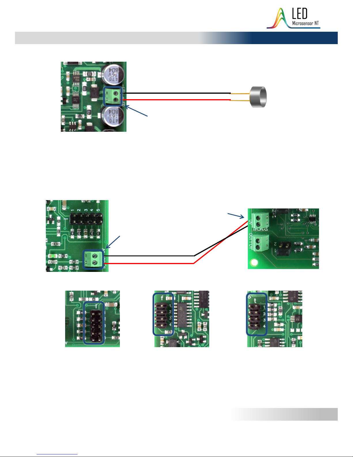
Light-emitting diode
Light-emitting diode Lms34LED-RW –LMSNT light-emitting diode with 3.4 µm peak
wavelength, in TO-18 package with a parabolic reflector. Main LED parameters are
pointed in Appendix 1. For detailed information and set of characteristics please refer
to the appropriate technical passport.
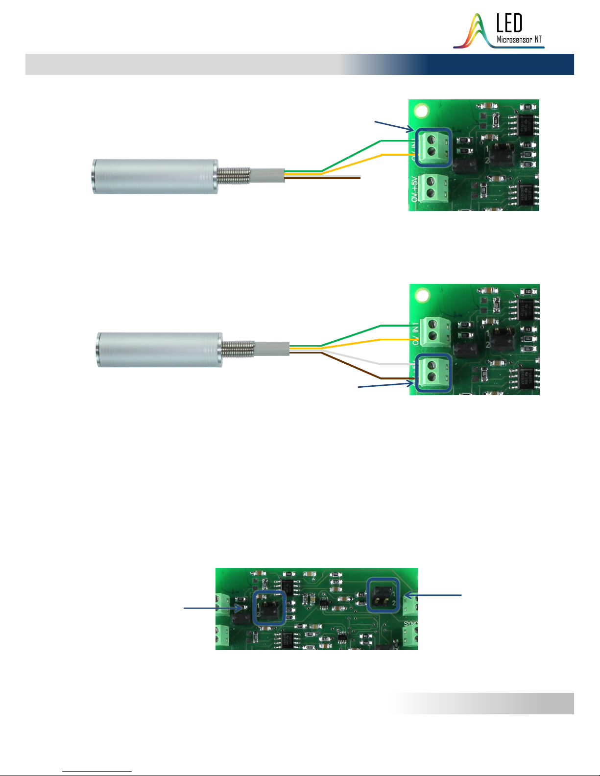
Photodiode with a built-in preamplifier
Photodiode Lms36PD-05-RW-PA –LMSNT photodiode with 3.6 µm cut-off wavelength,
with a built-in preamplifier, mounted in an aluminum tube with a parabolic reflector.
PD preamplifier amplifies the current generated by photodiode and converts it into
pulse voltage signal. There is straight correspondence between PD current and resulting
output voltage, i.e. if the photocurrent from photodiode is a meander, the converted
signal will be a meander too with the same frequency and pulse duration.
Main photodiode parameters are pointed in Appendix 2. For detailed information and
set of characteristics please refer to the appropriate technical passport.
D-51i/D-41i/mD-1p LED Driver (depends on customer request)
LED Driver is a power supply for an LED. D-41i/D-51i driver types have a
set of adjustable parameters to customise the desired operation mode
of an LED. mD-1p driver provides operation at one fixed pulse mode.
For brief information about drivers pleas e refer to Appendix 3. For
comprehensive information about the driver please refer to the driver’s
Instruction Manual.
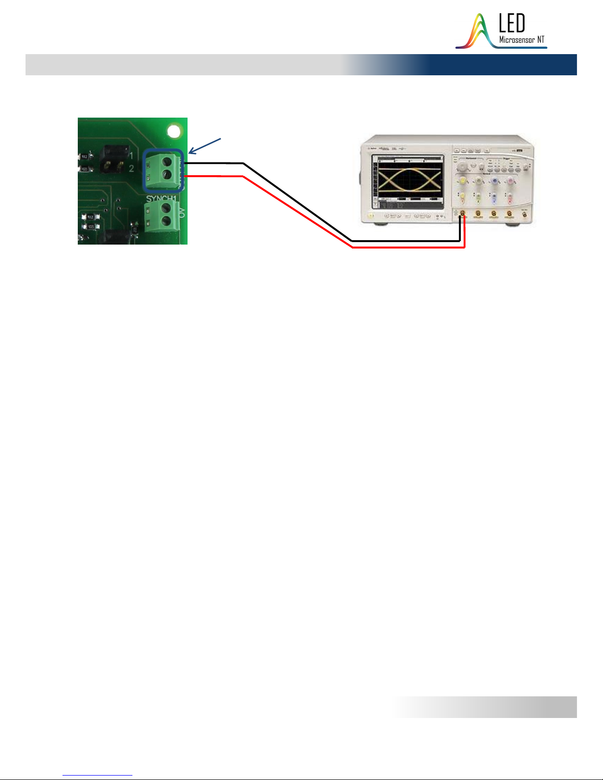
SDM Synchronous Detector
SDM synchronous detector measures the voltage signal from the
output of photodiode preamplifier and converts it to the DC voltage
signal proportional to amplitude of voltage from input.
For comprehensive information about the synchronous detector please
refer to the appropriate Instruction Manual.