manuals.online logo
Brands
  1. Home
  2. •
  3. Brands
  4. •
  5. Franklin
  6. •
  7. Controllers
  8. •
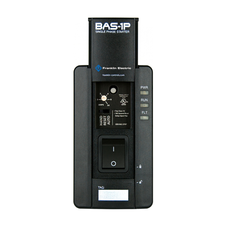
  9. Franklin BAS-1P Original operating instructions

Franklin BAS-1P Original operating instructions

Updated 9.11.14 © Copyright 2014 Franklin Control Systemswww.franklin-controls.com | 800.962.3787 | 22985 NW Evergreen Pkwy Hillsboro, OR 97124
Installation & Operation Guide
Thank you for purchasing the Franklin Control
Systems Single Phase Building Automation Starter!
Please read this manual thoroughly to ensure
safe installation and proper operation.
Precautions
To prevent injury and property damage, follow these instructions.
Failure to adhere to installation/operation procedures and all
applicable codes may result in hazards as indicated by warning
codes outlined below:
indicates an imminently hazardous situation which, if not avoided, will
result in death or serious injury. This signal word is to be limited to the
most extreme situations.
indicates a potentially hazardous situation which, if not avoided, could
result in death or serious injury.
indicates a potentially hazardous situation which, if not avoided, may
result in minor or moderate injury. It may also be used to alert against
unsafe practices.
This is the safety alert symbol. Read and follow instructions carefully to
avoid a dangerous situation.
This symbol alerts the user to the presence of “dangerous voltage”
inside the product that might cause harm or electrical shock.
DANGER
WARNING
CAUTION
Safety Instructions
Equipment starts automatically. Lockout/tagout before servicing.
As with all electrical products, read manual thoroughly. Only qualified,
expert personnel should perform maintenance and installation. Contact the
nearest authorized service facility for examination, repair, or adjustment.
Do not disassemble or repair unit unless described in this manual; death
or injury to electrical shock or fire hazard may result. Specifications and
manual data subject to change. Consult factory for additional information.
DANGER
CAUTION
1Ø AC Input 50/60 Hz
L1 L2/N
T1 T2
M
Voltage Input
Auto Run
Fault
Output
Status
Output
Dry Input
Auto Run
Normally Open
Input
12-120V
AC/DC
Input
Main Power Wiring
Wire main power input and output to the appropriate 12AWG wire leads utilizing
properly sized wire nuts. Use only copper conductors rated at least 60°C.
Maintain proper clearances and verify that no possibility of an electrical short
exists between the power conductors or enclosure. Ensure that wires are not
under stress and all insulation is intact.
Low Voltage Wiring
Automation system control wiring should be run in a separate conduit. The
control terminals accept 26~14AWG wire torqued to 3.5 in-lb.
Installation
FAILURE TO FOLLOW THESE INSTRUCTIONS MAY RESULT IN DEATH OR
SERIOUS INJURY
Mounting
Mount the starter on a minimum 14 cu-in single gang junction box. To access
mounting holes, slide upper and lower covers to the open position.
(See Figure 1)
Using provided mounting screws (6-32 x 7/8”), attach starter housing to junction
box (once appropriate wiring has been completed).
•
materials. Contact arcing can induce explosion or fire.
• Install starter in UL Type 1 (NEMA 1) appropriate locations only. Safe mounting
requires a dry, protected environment.
• The BAS-1P is rated for maximum ambient temperature of 40°C
• Do not allow any metal shavings or debris from installation to enter enclosure.
WARNING
Figure 1
HAZARDOUS VOLTAGE
• Disconnect and lock out all power before installing or servicing equipment.
• This equipment may require locking out multiple power sources prior to service
• Install and wire in accordance with all applicable local & national electrical and
construction codes
QSTART-BAS1P-V2 © Copyright 2014 Franklin Control Systemswww.franklin-controls.com | 800.962.3787 | 22985 NW Evergreen Pkwy Hillsboro, OR 97124
3.288
4.984
2.808
1.427
2.147
HAND
RESET
AUTO
All dimensions in inches
Dimensions
Operation
Overload Adjustment
onfir naeplate ull oad perae  to ensure proper oerload
protection sin a atead scredrier, turn te adustent dial to te desired
aperae settin e starter is not rated to protect loads eceedin  aps 
, and  
LED Status Indicators
POWER (PWR)
lluinates en oltae is applied to te input terinals and
ain poer sitc is in te   position.
RUN
nder a  condition, te   ill reain illuinated i
the BAS-1P senses current proidin status e  ill as
en te unit does not sense current
FAULT (FLT)  erload Trip
The BAS-1P indicates a ault condition  asin te red FAUT
 which will remain constant in the event of a ault trip. The 
ill also as i a ST attept is ade durin te  second
oerload cool don period
Operation Modes
RESET
To reset te starter to noral operation olloin a ault
condition, slide te position sitc to ST and old or
a iniu o  seconds ater  second cool don period
as elapsed nce starter as een reset, return sitc to te
desired ode
MANUAL (HAND MODE)
n anual or  ode, te SP ill unction as a
anual otor controller Select te  
position on the main
power switch to engage motor.
AUTOMATIC (AUTO MODE)
en utiliin te starter in te AUT ode, a sinal sent ia
te terinal inputs located on rear o unit deterine otor
operation  or 
Lockout Options
To locout, slide te loer coer upard to reeal concealed locin rasp
nsert a standard padloc to preent unautoried access or taperin 
ultiple padlocs are required, an optional padlocin attacent can e utilied
not included See iure 
Figure 2A Figure 2B
HAND
RESET
AUTO
PWR
RUN
FLT
Product Ratings
1
2
3
4
5
6
erload dustent
peration ode Selector
Main Power Switch*
PWR oer Status 
RUN un Status 
FLT ault  erload 
UL 508 Horsepower
Short Circuit Protection Interrupt
Current Max Current Overload Reset
115VAC 230VAC
BAS-1P
1HP
Suitale or use on a circuit capale o delierin not more
than 1kA RMS Symmetrical Amperes, 230 Volts aiu
en protected  lass  uses  p a or
inerse tie circuit reaer  p a
Ik  A RMS
Symmetrical
  
I2t Class 10
anual
BAS-1P-AR utoatic
 attepts a
1
2
3
4
5
6
*This device meets NFPA-70 (NEC) motor disconnect requirements per
paragraph 430.109 (C)(2) Stationary Motors of 2HP or Less.
 

Other Franklin Controllers manuals

Franklin BAS-1P Original operating instructions

Franklin

Franklin BAS-1P Original operating instructions

Popular Controllers manuals by other brands

Fermax 8053 manual

Fermax

Fermax 8053 manual

dymax BlueWave MX-Series Quick start instructions

dymax

dymax BlueWave MX-Series Quick start instructions

valent VX Series reference guide

valent

valent VX Series reference guide

Whelen Engineering Company MPC02 operating guide

Whelen Engineering Company

Whelen Engineering Company MPC02 operating guide

safgard 1100 instructions

safgard

safgard 1100 instructions

PPI neuro 102Plus user manual

PPI

PPI neuro 102Plus user manual

Nexmosphere Xperience XN-135M8S quick start guide

Nexmosphere

Nexmosphere Xperience XN-135M8S quick start guide

Paulmann 709.17 quick guide

Paulmann

Paulmann 709.17 quick guide

Sullair Supervisor II instruction manual

Sullair

Sullair Supervisor II instruction manual

Mi-Light MiBOXER LC2-ZR instruction manual

Mi-Light

Mi-Light MiBOXER LC2-ZR instruction manual

ELREHA TKP 3130/1 Technical manual

ELREHA

ELREHA TKP 3130/1 Technical manual

socomec ATyS C40 operating instructions

socomec

socomec ATyS C40 operating instructions

TSI Instruments PRESSURA 8631-CRM Operation and service manual

TSI Instruments

TSI Instruments PRESSURA 8631-CRM Operation and service manual

elsner elektronik KNX S2 Technical specifications and installation instructions

elsner elektronik

elsner elektronik KNX S2 Technical specifications and installation instructions

D-Box G5 quick start guide

D-Box

D-Box G5 quick start guide

Fright Ideas BooBox FlexMax quick start guide

Fright Ideas

Fright Ideas BooBox FlexMax quick start guide

Smartgen ACC4100 user manual

Smartgen

Smartgen ACC4100 user manual

RMG 672 OPERATING AND MAINTENANCE INSTRUCTIONS/ SPARE PARTS

RMG

RMG 672 OPERATING AND MAINTENANCE INSTRUCTIONS/ SPARE PARTS

manuals.online logo
manuals.online logoBrands
  • About & Mission
  • Contact us
  • Privacy Policy
  • Terms and Conditions

Copyright 2025 Manuals.Online. All Rights Reserved.