Sullair Supervisor II User manual

SUPERVISOR
Part Number 02250071---398
eSullair Corporation,
INSTRUCTION MANUAL
II
ALL MODELS

AIR CARE
SEMINAR TRAINING
Sullair AirCare Seminars are 3---day courses thatprovide hands---oninstruction
in the proper operation, maintenance and service of Sullair equipment.
Individual seminars on Industrial compressors and compressor electrical
systems are presented at regular intervals throughout the year at a dedicated
training facility at Sullair’s corporate headquarters in Michigan City, Indiana.
Instruction includes discussion of the function and installation of Sullair service
parts, troubleshooting of the most common problems, and actual equipment
operation. The seminars are recommended for maintenance and service
personnel.
For detailed course outlines, schedule and cost information contact:
Sullair Corporate Training Department
1---800---SULLAIR or 219---879---5451 (ext. 1816)
--- Or Write ---
Sullair Corporation
3700 E. Michigan Blvd.
Michigan City, IN 46360
Attn: Service Training Department

TABLE OF CONTENTS
Section 1 PAGE
SAFETY 11.1 GENERAL
11.2 ELECTRIC SHOCK
21.3 DECALS
Section 2
SUPERVISOR II DESCRIPTION
52.1 BASIC INTRODUCTION
52.2 KEYPAD --- ALL MODELS
52.3 STATUS DISPLAYS---SEE 2.3A THROUGH
2.3F FOR SPECIFIC MODELS
52.3A STATUS DISPLAYS --- ES --- 8
62.3B STATUS DISPLAYS --- LS --- 12, LS --- 16, LS --- 20
LS --- 20S, LS --- 25 AND EUROPE
72.3C STATUS DISPLAYS --- LS --- 25S & LS --- 32
82.3D STATUS DISPLAYS --- TS --- 20 & TS --- 32
10 2.3E STATUS DISPLAYS --- LS---16T & LS---20T
11 2.3F STATUS DISPLAYS --- DS --- 13
12 2.4 LAMP INDICATORS --- ALL MODELS
Section 3
COMPRESSOR OPERATION
15 3.1 STANDARD PARAMETER SETUP
15 3.2 DELUXE PARAMETER SETUP
16 3.3 OPERATING THE COMPRESSOR
17 3.4 PURPOSE OF CONTROLS
17 3.5 SUPERVISOR OUTPUT RELAYS
Section 4
START---UP PROCEDURES
19 4.1 MOTOR ROTATION DIRECTION CHECK
19 4.2 INITIAL START---UP PROCEDURE
19 4.3 SUBSEQUENT START---UP PROCEDURE
19 4.4 SHUTDOWN PROCEDURE

TABLE OF CONTENTS
Section 5 PAGE
MAINTENANCE AND
TROUBLESHOOTING 21 5.1 MAINTENANCE INTRODUCTION
21 5.2 DAILY OPERATION
21 5.3 TROUBLESHOOTING INTRODUCTION
21 5.4 TROUBLESHOOTING GUIDE---SEE 5.4A THROUGH
5.4D FOR SPECIFIC MODELS
21 5.4A TROUBLESHOOTING GUIDE --- ES --- 8
23 5.4B TROUBLESHOOTING GUIDE --- LS --- 12, LS --- 16, LS --- 20
LS --- 20S, LS --- 25 AND EUROPE
24 5.4C TROUBLESHOOTING GUIDE --- LS---16T & LS---20T
25 5.4D TROUBLESHOOTING GUIDE --- DS --- 13
28 NOTE ON TRANSDUCERS
28 5.5 CALIBRATION
Section 6
ORDERING PARTS 29 6.1 PROCEDURE FOR ORDERING PARTS

Section 1
SAFETY
1
1.1 GENERAL
Sullair Corporation and its subsidiaries design and
manufacture all oftheir products so they can be op-
erated safely. However, the responsibility for safe
operation rests with those who use and maintain
these products. For safe machine operation it is vi-
tally important to review all safety precautions
noted in the Safety Section of your compressor’s
Operator’s Manual. The precautions listed there,
as well as those following, are offered as a guide
which, if conscientiously followed, will minimize the
possibility of accidents throughout the useful life of
this equipment.
The compressor should be operated only by those
whohavebeentrainedanddelegatedtodoso,and
who have read and understood their compressor’s
Operator’s Manual. Failure to follow the instruc-
tions, procedures and safety precautions listed
here and in the Operator’s Manual may result inac-
cidents and injuries.
NEVER start the compressor unless it is safe to do
so. DO NOT attempt to operate the compressor
with a known unsafe condition. Tag the compres-
sor and render it inoperative by disconnecting and
locking out all power at source or otherwise disab-
ling its prime mover so others who may not know of
the unsafe condition cannot attempt to operate it
until the condition is corrected.
Use and operate the air compressor only in full
compliance with all pertinent OSHA requirements
or any pertinent Federal, State, and Local codes or
requirements.
DO NOT modify the compressor and/or controls in
any way except with written factory approval.
1.2 ELECTRICAL SHOCK
A. Keep all parts of the body and any hand---held
tools or other conductive objects away from ex-
posed live parts of electrical system. Maintain dry
footing, stand on insulating surfaces and DO NOT
contact any other portion of the compressor when
making adjustments or repairs to exposed live
parts of the electrical system.
B. Attempt repairs only in clean, dry and well
lighted and ventilated areas.
C. Stay clear of the compressor during electrical
storms! It can attract lightning.
1.3 DECALS
SeeFigure1---1.TheSupervisorII controlpanel
contains several decals which contain necessary
information for safe performance. These decals
should never be removed. If adecal becomes dam-
aged, contact your nearest Sullair Distributor orthe
Sullair Corporation factory Service Department for
replacement parts (Note: When ordering new de-
cals, use part number printed on decal face.).

Section 1
SAFETY
2
Figure 1---1 Decals

Section 2
SUPERVISOR II DESCRIPTION
3
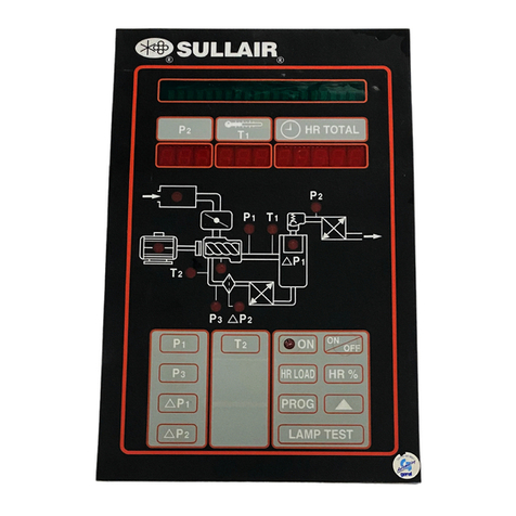
Figure 2 --- 1 Supervisor II Panel --- All Models Except DS --- 13

Section 2
SUPERVISOR II DESCRIPTION
4
Figure 2 --- 1A Supervisor Panel --- DS --- 13

Section 2
SUPERVISOR II DESCRIPTION
5
2.1 BASIC INTRODUCTION
RefertoFigure2---1.TheSupervisorII has atwo
linedisplay toshowtemperature, pressure andsta-
tus. It has a keypad for operating the compressor,
programming the control points and selecting dis-
plays. There isa graphic illustration with lamps that
light to show the item being displayed. The lamps
flash if that component is in an alarm condition.
2.2 KEYPAD---ALL MODELS
The keypad is used to control the machine as well
as display status and change setpoints. Refer to
figure 2---1for following keydescriptions.
SStop --- Used to put the machine into
manual stop. It is also used to clear alarm
conditions.
O
SContinuous --- Starts machine if no alarm
conditions are present. Also used to clear
alarm conditions whilemachine isrunning.
I
SAuto --- Starts machine and selects auto
mode if no alarm conditions are present.
Also used to clear alarm conditions while
machine is running.
S Display --- Used to display pressures,
temperatures and other status information
(See section on STATUS DISPLAYS).
DISPLY
SLogo --- Used for various functions de-
scribed in later sections
SProgram --- Used to enter the parameter
change mode where control parameters
may be displayed and changed (See PA-
RAMETER SETUP).
PROG
SUp arrow --- Used in status displays to
change displays and in parameter setup
mode to increment a value.
SDown arrow, lamp test --- Used in status
displays to change displays and in param-
eter setup mode to increment a value.
When inthe default display the key will light
all the lamps for three seconds.
2.3 STATUS DISPLAYS --- SEE 2.3A THROUGH 2.3F
FOR SPECIFIC MODELS
2.3 A STATU S DISPLAYS --- ES --- 8
By default the line pressure (P2) and discharge
temperature (T1) are shown on the bottom line of
the display, and machine status on the top line.
The following are the various machine status mes-
sages that indicate the state of the compressor:
(Display graphics shown below.)
SSTOP --- Compressor is off.
SSTANDBY --- Compressor is off but armed
tostart. This state maybe entered because
of a power up, or the unload timer had ex-
pired and stopped the machine. NOTE :
The machine may start at any time.
SSTARTING --- Machine is trying to start.
SOFF LOAD --- Machine is running and off
loaded.
SON LOAD --- Machine is running and
loaded.
SFULL LD --- Machine is running and fully
loaded. This state is only displayed if the
machine has a full load valve.
SRMT STOP --- Compressor is off but
armed to start. The machine will start when
the remote start contact is closed. NOTE :
the machine may start at any time.
SSEQSTOP --- Compressor isoffbutarmed
to start. The machine will start when the se-
quencing conditions meet the critera to
start. NOTE : the machine may start at any
time.
This default display appears as follows:
STOP
110 180

Section 2
SUPERVISOR II DESCRIPTION
6
If there are alarms active they will alternately be
shown withthe default display. The machine status
will bedisplayed for2seconds then the alarms for2
seconds each. For example:
T1 HI
110 180
To view other status press the DISPLY key. All tem-
peratures and pressures may be displayed as well
as other status information. To scroll through the
displays press the up arrow or down arrow keys.
Up arrow moves to the next display, down arrow
the previous display.Toreturn tothe default display
press the display key.
SSeparator differential pressure and the
maximum limit. If the limit is exceeded, a
separator maintenance warning will bedis-
played.
dP 1 4
MAX 10
SSump pressure and line pressure.
P1 113
P2 108
SUnit discharge temperature and the maxi-
mum limit. If the temperature exceeds the
limit a T1 HI shutdown will occur.
T1 210
MAX 235
STotal hours that the compressor has been
running.
HRS RUN
001234.0
STotal hours that the compressor has been
loaded.
HRS LOAD
000987.0
SLast fault log. This shows the fault on the
first line and the run hours when the fault
occcured.
T1 HI
@1 234
SNext to last fault log. This shows the fault
on the first line and the run hours when the
fault occcured.
T1 HI
@2 204
2.3B STATUS DISPLAYS --- LS---12; LS---16; LS---20;
LS --- 20S; LS --- 25 A ND EUROPE
By default the line pressure (P2) and discharge
temperature (T1) are shown on the bottom line of
the display, and machine status on the top line.
The following are the various machine status mes-
sages that indicate the state of the compressor:
(Display graphics shown below.)
SSTOP --- Compressor is off.
SSTANDBY --- Compressor is off but armed
tostart. This state maybe entered because
of a power up, or the unload timer had ex-
pired and stopped the machine. NOTE :
The machine may start at any time.
SSTARTING --- Machine is trying to start.
SOFF LOAD --- Machine is running and off
loaded.
SON LOAD --- Machine is running and
loaded.
SFULL LD --- Machine is running and fully
loaded. This state is only displayed if the
machine has a full load valve.
SRMT STOP --- Compressor is off but
armed to start. The machine will start when
the remote start contact is closed. NOTE :
the machine may start at any time.
SSEQSTOP --- Compressor isoffbutarmed
to start. The machine will start when the se-
quencing conditions meet the critera to
start. NOTE : the machine may start at any
time.
This default display appears as follows:
STOP
110 180

Section 2
SUPERVISOR II DESCRIPTION
7
If there are alarms active they will alternately be
shown withthe default display. The machine status
will bedisplayed for2seconds then the alarms for2
seconds each. For example:
T1 HI
110 180
To view other status press the DISPLY key. All tem-
peratures and pressures may be displayed as well
as other status information. To scroll through the
displays press the up arrow or down arrow keys.
Up arrow moves to the next display, down arrow
the previous display.Toreturn tothe default display
press the display key.
SSeparator differential pressure and the
maximum limit. If the limit is exceeded, a
separator maintenance warning will bedis-
played.
dP 1 4
MAX 10
SSump pressure and line pressure.
P1 113
P2 108
SUnit discharge temperature and the maxi-
mum limit. If the temperature exceeds the
limit a T1 HI shutdown will occur.
T1 210
MAX 235
STotal hours that the compressor has been
running.
HRS RUN
001234.0
STotal hours that the compressor has been
loaded.
HRS LOAD
000987.0
SLast fault log. This shows the fault on the
first line and the run hours when the fault
occcured.
T1 HI
@1 234
SNext to last fault log. This shows the fault
on the first line and the run hours when the
fault occcured.
T1 HI
@2 204
2.3 C --- STATUS DISPLAY S --- LS --- 2 5S & LS --- 3 2
By default the line pressure (P2) and discharge
temperature (T1) are shown on the bottom line of
the display, and machine status on the top line.
The following are the various machine status mes-
sages that indicate the state of the compressor:
(Display graphics shown below.)
SSTOP --- Compressor is off.
SSTANDBY --- Compressor is off but armed
tostart. This state maybe entered because
of a power up, or the unload timer had ex-
pired and stopped the machine. NOTE :
The machine may start at any time.
SSTARTING --- Machine is trying to start.
SOFF LOAD --- Machine is running and off
loaded.
SON LOAD --- Machine is running and
loaded.
SFULL LD --- Machine is running and fully
loaded. This state is only displayed if the
machine has a full load valve.
SRMT STOP --- Compressor is off but
armed to start. The machine will start when
the remote start contact is closed. NOTE :
the machine may start at any time.
SSEQSTOP --- Compressor isoffbutarmed
to start. The machine will start when the se-
quencing conditions meet the critera to
start. NOTE : the machine may start at any
time.
This default display appears as follows:
STOP
110 180

Section 2
SUPERVISOR II DESCRIPTION
8
If there are alarms active they will alternately be
shown withthe default display. The machine status
will bedisplayed for2seconds then the alarms for2
seconds each. For example:
T1 HI
110 180
To view other status press the DISPLY key. All tem-
peratures and pressures may be displayed as well
as other status information. To scroll through the
displays press the up arrow or down arrow keys.
Up arrow moves to the next display, down arrow
the previous display.Toreturn tothe default display
press the display key.
SSeparator differential pressure and the
maximum limit. If the limit is exceeded, a
separator maintenance warning will bedis-
played.
dP 1 4
MAX 10
SSump pressure and line pressure.
P1 113
P2 108
SOil filter differential pressure and the maxi-
mum limit. If the limit is exceeded oil main-
tenance warning will be displayed.
dP2 4
MAX 20
SPressure before(P4)and after (P3)oilfilter.
P3 108
P4 113
SOil differential pressure and the minimum
limit. If the pressure goes below the limit a
P3LOWshutdown will occur.Oildifferential
(dP3) is defined as P3---P1/2
dP3 40
MIN 1
SUnit discharge temperature and the maxi-
mum limit. If the temperature exceeds the
limit a T1 HI shutdown will occur.
T1 210
MAX 235
SDry side discharge temperature and the
maximum limit. If the temperature exceeds
the limit a T2 HI shutdown will occur.
T2 210
MAX 235
SOil temperature and the maximum limit.
If the temperature exceeds the limit a T3 HI
shutdown will occur.
T3 210
MAX 235
STotal hours that the compressor has been
running.
HRS RUN
001234.0
STotal hours that the compressor has been
loaded.
HRS LOAD
000987.0
SLast fault log. This shows the fault on the
first line and the run hours when the fault
occcured.
T1 HI
@1 234
SNext to last fault log. This shows the fault
on the first line and the run hours when the
fault occcured.
T1 HI
@2 204
2.3 D STATUS DISPLAYS --- TS --- 20 & TS --- 32
By default the line pressure (P2) and discharge
temperature (T1) are shown on the bottom line of
the display, and machine status on the top line.
The following are the various machine status mes-
sages that indicate the state of the compressor:
(Display graphics shown below.)
SSTOP --- Compressor is off.
SSTANDBY --- Compressor is off but armed
tostart. This state maybe entered because
of a power up, or the unload timer had ex-
pired and stopped the machine. NOTE :
The machine may start at any time.
SSTARTING --- Machine is trying to start.
SOFF LOAD --- Machine is running and off
loaded.
SON LOAD --- Machine is running and
loaded.

Section 2
SUPERVISOR II DESCRIPTION
9
SFULL LD --- Machine is running and fully
loaded. This state is only displayed if the
machine has a full load valve.
SRMT STOP --- Compressor is off but
armed to start. The machine will start when
the remote start contact is closed. NOTE :
the machine may start at any time.
SSEQSTOP --- Compressor isoffbutarmed
to start. The machine will start when the se-
quencing conditions meet the critera to
start. NOTE : the machine may start at any
time.
This default display appears as follows:
STOP
110 180
If there are alarms active they will alternately be
shown withthe default display. The machine status
will bedisplayed for2seconds then the alarms for2
seconds each. For example:
T1 HI
110 180
To view other status press the DISPLY key. All tem-
peratures and pressures may be displayed as well
as other status information. To scroll through the
displays press the up arrow or down arrow keys.
Up arrow moves to the next display, down arrow
the previous display.Toreturn tothe default dispaly
press the display key.
SSeparator differential pressure and the
maximum limit. If the limit is exceeded, a
separator maintenance warning will bedis-
played.
dP 1 4
MAX 10
SSump pressure and line pressure.
P1 113
P2 108
SOil filter differential pressure and the maxi-
mum limit. If the limit is exceeded oil main-
tenance warning will be displayed.
dP2 4
MAX 20
SPressure before(P4)and after (P3)oilfilter.
P3 108
P4 113
SOil differential pressure and the minimum
limit. If the pressure goes below the limit a
P3LOWshutdown will occur.Oildifferential
(dP3) is defined as P3---P½
dP3 40
MIN 1
SUnit discharge temperature and the maxi-
mum limit. If the temperature exceeds the
limit a T1 HI shutdown will occur.
T1 210
MAX 235
SDry side discharge temperature and the
maximum limit. If the temperature exceeds
the limit a T2 HI shutdown will occur.
T2 210
MAX 235
SOil temperature and the maximum limit.
If the temperature exceeds the limit a T3 HI
shutdown will occur.
T3 210
MAX 235
SInterstage temperature and the maximum
limit. If the temperature exceeds the limit a
T4 HI shutdown will occur.
T4 210
MAX 235
STotal hours that the compressor has been
running.
HRS RUN
001234.0
STotal hours that the compressor has been
loaded.
HRS LOAD
000987.0

Section 2
SUPERVISOR II DESCRIPTION
10
SLast fault log. This shows the fault on the
first line and the run hours when the fault
occcured.
T1 HI
@1 234
SNext to last fault log. This shows the fault
on the first line and the run hours when the
fault occcured.
T1 HI
@2 204
2.3E STATUS DISPLAYS --- LS---16T & LS---20T
By default the line pressure (P2) and discharge
temperature (T1) are shown on the bottom line of
the display, and machine status on the top line.
The following are the various machine status mes-
sages that indicate the state of the compressor:
(Display graphics shown below.)
SSTOP --- Compressor is off.
SSTANDBY --- Compressor is off but armed
tostart. This state maybe entered because
of a power up, or the unload timer had ex-
pired and stopped the machine. NOTE :
The machine may start at any time.
SSTARTING --- Machine is trying to start.
SOFF LOAD --- Machine is running and off
loaded.
SON LOAD --- Machine is running and
loaded.
SFULL LD --- Machine is running and fully
loaded. This state is only displayed if the
machine has a full load valve.
SRMT STOP --- Compressor is off but
armed to start. The machine will start when
the remote start contact is closed. NOTE :
the machine may start at any time.
SSEQSTOP --- Compressor isoffbutarmed
to start. The machine will start when the se-
quencing conditions meet the critera to
start. NOTE : the machine may start at any
time.
This default display appears as follows:
STOP
110 180
If there are alarms active they will alternately be
shown withthe default display. The machine status
will bedisplayed for2seconds then the alarms for2
seconds each. For example:
T1 HI
110 180
To view other status press the DISPLY key. All tem-
peratures and pressures may be displayed as well
as other status information. To scroll through the
displays press the up arrow or down arrow keys.
Up arrow moves to the next display, down arrow
the previous display.Toreturn tothe default display
press the display key.
SSeparator differential pressure and the
maximum limit. If the limit is exceeded, a
separator maintenance warning will bedis-
played.
dP 1 4
MAX 10
SSump pressure and line pressure.
P1 113
P2 108
SOil filter differential pressure and the maxi-
mum limit. If the limit is exceeded oil main-
tenance warning will be displayed.
dP2 4
MAX 20
SPressure before(P4)and after (P3)oilfilter.
P3 108
P4 113
SOil differential pressure and the minimum
limit. If the pressure goes below the limit a
P3LOWshutdown will occur.Oildifferential
(dP3) is defined as P3---P1/2
dP3 40
MIN 1
SUnit discharge temperature and the maxi-
mum limit. If the temperature exceeds the
limit a T1 HI shutdown will occur.
T1 210
MAX 235
SDry side discharge temperature and the
maximum limit. If the temperature exceeds
the limit a T2 HI shutdown will occur.

Section 2
SUPERVISOR II DESCRIPTION
11
T2 210
MAX 235
SOil temperature and the maximum limit.
If the temperature exceeds the limit a T3 HI
shutdown will occur.
T3 210
MAX 235
SInterstage temperature and the maximum
limit. If the temperature exceeds the limit a
T4 HI shutdown will occur.
T4 210
MAX 235
STotal hours that the compressor has been
running.
HRS RUN
001234.0
STotal hours that the compressor has been
loaded.
HRS LOAD
000987.0
SLast fault log. This shows the fault on the
first line and the run hours when the fault
occcured.
T1 HI
@1 234
SNext to last fault log. This shows the fault
on the first line and the run hours when the
fault occcured.
T1 HI
@1 204
2.3 F STATUS DISPLAY S --- DS --- 13
By default the line pressure (P2) and discharge
temperature (T1) are shown on the bottom line of
the display, and machine status on the top line.
The following are the various machine status mes-
sages that indicate the state of the compressor:
(Display graphics shown below.)
SSTOP --- Compressor is off.
SSTANDBY --- Compressor is off but armed
tostart. This state maybe entered because
of a power up, or the unload timer had ex-
pired and stopped the machine. NOTE :
The machine may start at any time.
SSTARTING --- Machine is trying to start.
SOFF LOAD --- Machine is running and off
loaded.
SON LOAD --- Machine is running and
loaded.
SFULL LD --- Machine is running and fully
loaded. This state is only displayed if the
machine has a full load valve.
SRMT STOP --- Compressor is off but
armed to start. The machine will start when
the remote start contact is closed. NOTE :
the machine may start at any time.
SSEQSTOP --- Compressor isoffbutarmed
to start. The machine will start when the se-
quencing conditions meet the critera to
start. NOTE : the machine may start at any
time.
This default display appears as follows:
STOP
110 350
If there are alarms active they will alternately be
shown withthe default display. The machine status
will bedisplayed for2seconds then the alarms for2
seconds each. For example:
T1 HI
110 350
To view other status press the DISPLY key. All tem-
peratures and pressures may be displayed as well
as other status information. To scroll through the
displays press the up arrow or down arrow keys.
Up arrow moves to the next display, down arrow
the previous display.Toreturn tothe default display
press the display key.
SInterstage discharge pressure and line
pressure.
P1 30
P2 110
SOil filter differential pressure and the maxi-
mum limit. If the limit is exceeded oil main-
tenance warning will be displayed.
dP2 4
MAX 20
SPressure before(P4)and after (P3)oilfilter.

Section 2
SUPERVISOR II DESCRIPTION
12
P3 65
P4 69
SInterstage discharge temperature. Shuts
offthecompressoritT1exceedsT1MAX
and system status will display T1 HI.
T1 350
MAX 425
SFinal discharge temperature and the maxi-
mum limit. If the temperature exceeds the
limit a T2 HI shutdown will occur.
T2 350
MAX 425
SOil temperature and the maximum limit.
If the temperature exceeds the limit a T3 HI
shutdown will occur.
T3 100
MAX 170
SInterstage temperature after the intercool-
er and the maximum limit. If the tempera-
ture exceeds the limit a T4HI shutdown will
occur.
T4 100
MAX 170
SPackage discharge temperature and the
maximum limit. If the temperature exceeds
the limit a T5 HI shutdown will occur.
T5 100
MAX 170
STotal hours that the compressor has been
running.
HRS RUN
001234.0
STotal hours that the compressor has been
loaded.
HRS LOAD
000987.0
SLast fault log. This shows the fault on the
first line and the run hours when the fault
occcured.
T1 HI
@1 234
SNext to last fault log. This shows the fault
on the first line and the run hours when the
fault occcured.
T1 HI
@2 204
2.4 LAMP INDICATORS --- ALL MODELS
Embedded into the front panel schematic of the
compressor are several lamps. Pressing the lamp
test key will light all the lamps for 3 seconds. Each
LED lamp has the following purpose.
P1 --- (Sump andline pressure) Iflitsteady,signifies
that P1 is being displayed, if flashing denotes the
presence of an alarm.
P2 --- (Sump andline pressure) Iflitsteady,signifies
that P2 is being displayed, if flashing denotes the
presence of an alarm.
P3 --- (Pressure after oil filter) Same as P1 & P2 ex-
cept for P3. (Pressure after oil filter)
P4 --- (Pressure before oil filter)
dP1 --- (Separate differential pressure) If lit steady,
signifies that dP1 is being displayed, if flashing de-
notes replacement of separator is needed.
dP2 --- (Oil filter differential pressure)
dP3 --- (Oil differential pressure)
T1 --- (Dry side discharge temperature) If lit steady,
signifies that T1 is being displayed, if flashing de-
notes the presence of an alarm.
T2 --- (Discharge temperature) If lit steady,signifies
that T2 is being displayed, if flashing denotes the
presence of an alarm.
T3 --- (Oil temperature) If lit steady, signifies that T3
isbeing displayed, if flashing denotes the presence
of an alarm.
T4 --- (Interstage temperature) If lit steady, signifies
that T4 is being displayed, if flashing denotes the
presence of an alarm.
T5 --- (Package discharge temperature)
MOTOR --- If flashing, indicates the motor overload
contact has opened.
INLET FILTER --- If flashing, indicates that inlet filter
maintenance is needed.
OIL FILTER --- If flashing, indicates that oil filter
maintenance is needed.
POWER ON --- Litif120VAC power isapplied tothe
Supervisor II.
ON --- If lit steady, the compressor is running. If
flashing, indicates that the compressor is armed
but stopped because of restart timer not expired,
remote stop or sequence stop. The compressor
may start at any time.

Section 2
SUPERVISOR II DESCRIPTION
13
AUTO --- Iflitsteady,the compressor is running and
in auto mode. If flashing, indicates that the com-
pressor is armed but stopped because of restart
timer not expired, remote stop or sequence stop.
The compressor may start at any time.

14
NOTES

Section 3
COMPRESSOR OPERATION
15
3.1 STANDARD PARAMETER SETUP
Pressing the program key enters parameter dis-
play and edit mode. To move tothe next parameter
press the program key. To increment a parameter
press the up arrow key or logo key. The logo key
will increment by 10. To decrement the value press
the down arrow key.
The parameters are displayed in the following or-
der:
SUnload pressure --- The pressure where
the machine is unloaded. For example if
this parameter is set to 110 PSI (7.6 bar)
the machine willunload when the line pres-
sure is above 110 PSI (7.6 bar).
UNLOAD
100 PSI
SLoad differential --- The pressure differ-
ential below theunload pressure wherethe
machine is loaded. For example if the un-
load pressure is set to 110 PSI (7.6 bar)
and the load differential is set to 10 PSID
(0.7 bar), the machine will load when the
linepressure goesbelow 100PSI (6.9bar).
LOAD
10 PSI
SP1 Max --- Maximum sump pressure. An
alarm and shut down will occur when the
sump pressure rises above this pressure.
P1 MAX
135 PSI
SWye to delta transition timer --- For full
voltage starters this parameter is set to 0.
WYE DELT
10 SEC
SRestart time --- Time towait after powerup
before starting machine. This parameter is
used to keep several machines from start-
ing at the same time after power up, or to
delay start until other equipment is started.
If disabled the machine will not automati-
cally start after power up.
RST TIME
10 SEC
SUnload Stop Timer --- If the machine is
running in AUTO mode, this parameter
specifies the ammount of time that the ma-
chine will run unloaded before shutting off.
Ifthetimeissetlessthan15minutes(for
example 5), there may be times when the
machine will run unloaded for more than 5
minutes. This is because there is another
timer that keeps the machine from being
started more than four times an hour.
UNLD TIM
15 MIN
SLanguage select --- English, German,
Spanish, Italian and French may be se-
lected for display language.
LANGUAGE
ENGLISH
SUnits --- English or metric units may be se-
lected.
UNITS
ENGLISH
SCommunications ID # --- This is the net-
work address ofamachine. Ifthere ismore
that one machine connected to the net-
work, each machine must have a unique
number
COM ID #
1
SCommunications baud rate --- This
should always be selected to 9600 baud
for all sequencing modes. It may be lower
for slave or monitoring modes.
BAUDRATE
9600
3.2 DELUXE PARAMETER SETUP
The following parameters are only available on de-
luxe model Supervisor II.
SSequence method --- This parameter sets
the method used for sequencing. The
choices are DISABLED, REMOTE, SLAVE,
HOURS, COM ID#. See the Sequencing &
Protocol Manual (P/N 02250057---696) for
details about these modes.
SEQUENCE
HOURS

Section 3
COMPRESSOR OPERATION
16
SDrain interval --- The time between actua-
tion of the drain valve.
DRN INTV
10 MIN
SDrain time --- The amount of time that the
drain valve is actuated.
DRN TIM
1SEC
SLast Communication Number --- Used
only for sequencing, see Sequencing &
Protocol Manual for details.
LAST COM
3
SLowest Allowable Pressure --- Used only
for sequencing, see Sequencing & Proto-
col Manual for details.
LOWEST
90 PSI
SRecovery Time --- Used only forsequenc-
ing, see Sequencing &Protocol Manual for
details.
RECOVER
10 SEC
SRotate Time --- Used only for sequencing,
see Sequencing & Protocol Manual for de-
tails.
ROTATE
50
SMachine Capacity --- Used only for se-
quencing, see Sequencing & Protocol
Manual for details.
CAPACITY
100
SSequence Hours --- Used only for se-
quencing, see Sequencing & Protocol
Manual for details.
SEQ HRS
1000
3.3 OPERATING THE COMPRESSOR
Before operating the compressor the operating pa-
rameters must be setup. See the previous section
on operating parameter setup.
MANUAL OPERATION MODE
In this mode the compressor will run indefinitely, as
long as temperatures and pressure remain within
the valid operating ranges, and the motoroverload
or emergency stop contacts are not tripped. Press-
ing the “I”will turn on the compressor and put it in
manual mode. If the compressor is already run-
ning, but in automatic mode, pressing “I”will
switch operation to manual. Pressing “I”whileal-
ready running in manual mode will cause the Su-
pervisor to turn off the common fault relay, if en-
gaged, and clear any maintenance indicators.
Tostop the compressor,press “O”. If the compres-
soris already off when “O”ispressed, the common
fault relay will beturned off,if engaged, and it will try
to clear the alarm and maintenance indicators. Re-
gardless ofwhat thecompressor is doing, pressing
“O” puts the Supervisor in manual stop mode.
AUTOMATIC OPERATION MODE
In this mode the compressor will start if line pres-
sure (P2) is less than the LOAD parameter. It will
stop if the compressor runs unloaded for the num-
berofminutes indicated by theUNLDTIMparame-
ter . To put the compressor in automatic mode
press “ ”.If P2isalready less than LOAD the com-
pressor will start immediately, otherwise the sys-
tem status will indicate STANDBY and the LED
marked AUTO will flash.
Ifthe compressor isalready running, butincontinu-
ous mode, pressing “ ” will switch operation to
automatic. Pressing “ ” while already running in
automatic mode will cause the Supervisor to turn
off the common fault relay, if engaged, and clear
any maintenance indicators.
In automatic mode the compressor can be
stopped manually by pressing O. Stopping the
compressor using Owill put the Supervisor in
manual stop mode.
Regardless of whether in ”automatic” or ”manual”
mode, control of the load solenoid will be based on
the parameters UNLDand LOAD. This operation is
as follows:
P2 > UN LD --- --- > loa d solenoi d turn ed off
P2 < LOAD --- --- > load solenoid turn ed on
POWER FAILURE RESTART
If the restart timer (RST TIME parameter) is dis-
abled the compressor will not try to start after a
power up. If this time is set to a value the machine
will go into standby after power up. When the line
pressure drops below the load setpoint, the restart
timer will start timing. When the timer expires the
machine will start.
SEQUENCING MODES
The following is a brief description of sequencing
modes, for details see the Supervisor II Sequenc-
ing & Protocol Manual (P/N 02250057---696).
SDISABLED --- Responds to status and
Table of contents
Other Sullair Controllers manuals

Sullair
Sullair EC2000 User manual

Sullair
Sullair Supervisor IE User manual

Sullair
Sullair 02250165-411 R01 User manual

Sullair
Sullair 02250160-842 User manual

Sullair
Sullair SUPERVISOR I User manual

Sullair
Sullair SUPERVISOR CONTROLLER User manual

Sullair
Sullair 900 User manual

Sullair
Sullair SUPERVISOR II Series User manual

Sullair
Sullair SUPERVISOR CONTROLLER Series User manual

Sullair
Sullair SUPERVISOR CONTROLLER User manual