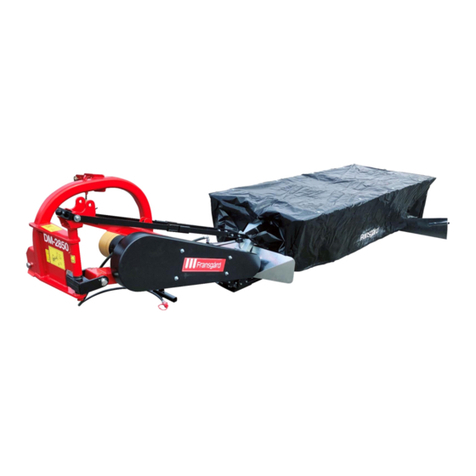
Fransgard FKR-1501 User manual

Fransgård
Manual
GB
Chain mower
FKR-1501
Serial no. 63500268 →

1
TABLE OF CONTENTS Page
Technical data..............................................................1
Foreword ......................................................................1
Assembly on the tractor / parking.................................1
Safety regulations.........................................................2
Use of the machine.......................................................3
Working position...........................................................3
Collision protection.......................................................3
Transportation position.................................................3
Lubrication and maintenance........................................4
Belt tensioners...........................................................5-6
Replacing chains..........................................................7
Ordering spare parts.....................................................7
Assembly instructions...................................................7
TECHNICAL DATA
Working width........................................................ 1.5 m
Transportation width.............................................. 2.5 m
Working speed................................................ 6-10 km/h
Power requirement.................................... 45 PS/34 kW
Power take-off .........................................540/1,000 rpm
Number of chains .........................................................2
Weight ..................................................................910 kg
Recommended tractor weight.............................5000 kg
Foreword
The FKR-1501 chain mower from Fransgård is designed to remove bushes, heather
and small trees, primarily on remote forest roads. The chain mower has proven to be
a cost-effective and efficient piece of machinery for removing self-sowed vegetation.
The remaining stumps become very frayed and dry up very quickly.
Important
In some cases, the tractor can be too powerful in comparison to the chain mower.
The power take-off (540/1000 rpm) should therefore be adjusted in relation to the
power requirement.
Assembly on the tractor
The FKR-1501 chain mower from Fransgård is assembled in the tractor’s three-point
hitch with the towing pin included. The lifting pins are cat. 2-3 and must be fitted so
that they fit the lifting arm’s hole size. The PTO axle is fitted and the chains are attached
so that the casing does not rotate. The supporting legs are lifted up and the machine
is ready for use.
Parking
When the machine needs to be parked, the cutting head is lowered and the machine
must be located on a horizontal, firm and level surface, the machine's 4 supporting
legs are also lowered so that the three-point hitch is stable.

2
SAFETY REGULATIONS.
It is obligatory to read through the instructions for use before commissioning.
All the guards must be in place and checked before the machine is started up.
Beware of projected stones. It is the owner's / user's responsibility to ensure
that there are no people or other living things within the machine's working area
when the machine is started up; if this happens while the machine is in use, it
must be stopped immediately and the individuals moved away.
The safety distance / risk zone is a 50 m radius from the machine at 540 rpm on
the power transmission’s axle.
The cab must not be left unattended when the machine is in use.
The machine is designed to remove small trees, bushes and small foliage and must
not be used for anything else.
The machine must only be operated by trained individuals.
When being operated in more densely populated areas, caution should be taken with
the machine’s risk zone.
Lubrication, adjustment and setting of the machine must only be undertaken when the
latter has stopped and the power has been switched off. The key must be removed
from the tractor so that the latter cannot be started.
When driving on very dry terrain, be aware that the chains can cause sparks, with a
subsequent risk of fire, if they rub against stones or rocks.
Never drive so fast that it is impossible to stop if an obstacle arises.
Tighten bolts and check settings after every 7 hours of operation.
The machine must only be started up when the impactor head is in the lowered
and horizontal position.
The prescribed speed of the power transmission must not be exceeded.
Large foreign objects that may present a danger must be removed from the area where
the machine is to be used.
The rubber protection plates that sit behind the cutting head are subject to wear and
tear and must be replaced when they begin to crack or show signs of wear and no later
than every third year.
The chains and the chain case are subject to wear and tear and must be examined at
regular intervals, at least after every 7 hours of use, and then tightened.
The chain must be replaced if it has worn down to 2.0 mm below the nominal dimension
(10 mm or 13 mm chain). If the mounts that hold the chains are worn to 2.0 mm below
the nominal dimensions (10 mm), these must be replaced.
If the chains need to be replaced, it must be ensured that they are located correctly
and that there is an equal distance to each side of the chain case, where 2 or 4 have
to be used, but if the machine is operated with 2 chains, these must be located opposite
one another.
The length must be adapted so that, with a 10 mm chain, the locking fork sits above
the 20th link, and above the 16th link in a 13 mm chain.
If the machine is serviced with the cutting head in a vertical position, the locking
valve, item 2, must be closed. See Fig. 1.
The cutting head must be lowered to the ground.

3
Use of the machine
Before the cutting head can be lowered to its working position, the locking valve, item
2, must be opened and the cutting head lowered with the help of the hydraulic system.
Then the cutting head is turned hydraulically to the side to the desired position, and
the machine is lowered in the lift so that it rests against the ground. Remember to
ensure that no people or other living things are inside the risk zone before the
power take-off is connected and operated up to a maximum of 540 rpm then slowly
driven forward. The speed needs to be adapted to the condition of the vegetation.
WORKING POSITION
The machine is designed to work, from the side, from both a horizontal and vertical
position, to an incline of approx.± 35°.
The machine must only be started when the stroke head is in the lowered position.
With the help of parallel mounts, the machine can be shifted hydraulically approx. 1.5
m to the side, which enables a greater degree of freedom while working, and it is
important here to check that the power transmission axle operates freely in the three-
point hitch when the machine is shifted all the way to the right.
Prior to commissioning, the chains must be examined for damage and replaced if
necessary (see safety regulations).
Operate the machine so that it rests more on the rearmost part of the stroke head
rather than the frontmost part.
Try not to force the machine through dense and rough vegetation, rather operate at
the speed that gives the best and most effective processing, as this extends the
machine’s lifetime and reduces the use of spare parts.
The chain box rotates at a speed of approx. 1,550 rpm
with power take-off equalling 540 rpm.
COLLISION PROTECTION
On the right-hand side parallel mounting, the machine is fitted with collision protection
when the machine is operating, where two powerful springs will protect the machine in
the event of a collision. Please be aware that the collision protection only operates
when driving forward, and it must be lifted free of obstructions if there is a need for the
machine to reverse (tem 1.)
TRANSPORTATION POSITION
The machine is shifted from its working position to its transportation position in the
following way:
The machine is lifted from the ground.
The stroke head is raised into the vertical position with the help of the hydraulic system
andsecured by closing the locking valve (Fig. 1, Item 2), which sits on the large cylinder
on the cutting head.
The machine is pulled back into the tractor, with parallel displacement.

4
LUBRICATION AND MAINTENANCE
As the machine may be exposed to major influences, it is important to look for loose
parts and tighten bolts after every 7 hours of operation.
The machine should be examined for any damage, and if damage is found on any
parts that can be replaced with spare parts, this should be done. Any damaged found
must be repaired properly and professionally.
After every 10 hours of operation, lubricate the power transmission axle, all moving
joints and all lubrication points indicated by the “lubricator”.
The oil level of the angle gear is checked using the dipstick that sits on top of the plug
on the angle gear. The angle gear is filled at the factory with 2.7 litres of SAE W80/90
gear oil.
The oil must be changed after approx. 10 hours of operation and then regularly after
approx. 100 hours of operation, although at least once a year.

5
Fig. 1.
Adjustment of V-belts
The V-belts are equipped with automatic spring tensioners that are set at the factory.
After 5 hours of operation, it is important to check that the belts are not too loose by
this you can avoid wear on the belts and the belt pulleys.
For every 10 hours of operation, it is important to check the belts for wear and tear,
and any defective belt must be replaced.
When the machine is parked and not to be used for an extended period of time, the
V-belt must be loosened.
Powerbelts
1
Fig. 2
Se Fig. 1
2

- 6 -
Tightening of V-belts
Fig. 1 Pos 4
The belt for the chain head (with clamping roller) must be tightened so that it is pressed 1 cm down with
7 kg force between the pulleys.
Fig. 1 Pos 3
The strap coming from the tractor must be tightened so that it presses down 1 cm with 11 kg of force
between the pulleys.
The outer strap is initially tightened by releasing bolt 2 in FIG. 2. The bolt 1 is then adjusted in
FIG. 2. This is tightened max so adjust with cylinder Pos. 3. Adjust the inner strap by turning the
Pos. 3

- 7 -
Fig. 2
ADJUSTING THE COLLISION SPRINGS
The springs are adjusted according to the following dimensions on the bracket which
holds the springs, see picture below.
After 5 hours of driving, the springs are adjusted so that there is 1mm between the
turns.
Fitting the belt drive.
The belt pulleys must be aligned and the shafts must be parallel.
The large belt pulley can be adjusted by adjusting the M16 threaded bolt at the PTO
bracket See Fig. 2
After approx. 10 - 20 min. the V-belts must be able
to be tightened a maximum of 15 mm per metre in tension, if the belt is defective it
must be replaced. If the belt is new, it should be tightened a few times, this can help
the belt last longer and avoid downtime.
The belt should be tightened so much that it feels "alive" when it is vibrated with a
finger. If it seems "dead", it is too slack, and if it plays like a violin string, it is too tight.
Overtightening the belt will ruin the cord and cause unnecessary bearing stress.
Right
Wrong

- 7 -
If a closer check of the belt tension is desired, it can be done in the following way: the
tension is measured as shown in the sketch. A force K, perpendicular to the span,
sufficient to bend the belt down 15 mm per 1 m of span, shall be applied at the centre
of the span. The bending force for each V-belt should be within the minimum and
maximum force listed in the table.
The table applies to the classics.
Power transfer.
Poor power transfer may be due to:
a. Incorrect mounting of the belt drive.
b. Dirt, oil, grease, paint and rust on belts and pulleys. Oil and grease on the pulleys can
be washed off with mineral turpentine, benzene, trichloroethylene, carbon tetrachloride
substance and similar.
Oil and grease on ordinary V-belts will eventually dissolve the rubber. Wipe
the belts with a clean cloth, possibly with a little turpentine or similar.
Paint and rust on the pulley can be removed with emery cloth. The pulley
should preferably be rotating, possibly clamped to a lathe bench during
cleaning.
c. The belts/pulleys are worn, so the belts go in the bottom of the tracks. If the belt
pulley is shiny at the bottom of the track, this is probably the problem.
d. The belt cord is destroyed due to:
Overtightening the belts.
New and used belts in the same drive or attachment with a screwdriver.
New belts should not be used in sets with used ones, as the result will be that
the new belts wear out quickly due to uneven distribution of the load.
The belt must never be forced over the pulleys, e.g. with a screwdriver.
Instead, the centre distance is reduced, or the tension roller is relaxed so that
the belt can be put on by hand.
Deflection force K (per belt)
Belt profil K min. K Max
Newton Newton
Deflection
Correct in-correct

- 7 -
Storing the belt drive.
When machines are left for a long time with tensioned belt drives and in a damp
environment, the following occurs:
a.
The belt pulleys rust and cause a reduction in power transfer. The belt wears
out from the rust.
b.
The belts will be shaped to the pulleys and may run with the inside outwards
or snap at start-up.
c.
The bearing ring can be destroyed due to the tightening.
It is therefore desirable:
To remove the belts and put them in a dry and cool place. When hanging, this
should be done on a curve or similar, never on a nail.
To rustproof the belt pulley with special grease or oil.


This manual suits for next models
1
Table of contents
Other Fransgard Lawn Mower manuals