3
REMOTE KEYLESS ENTRY
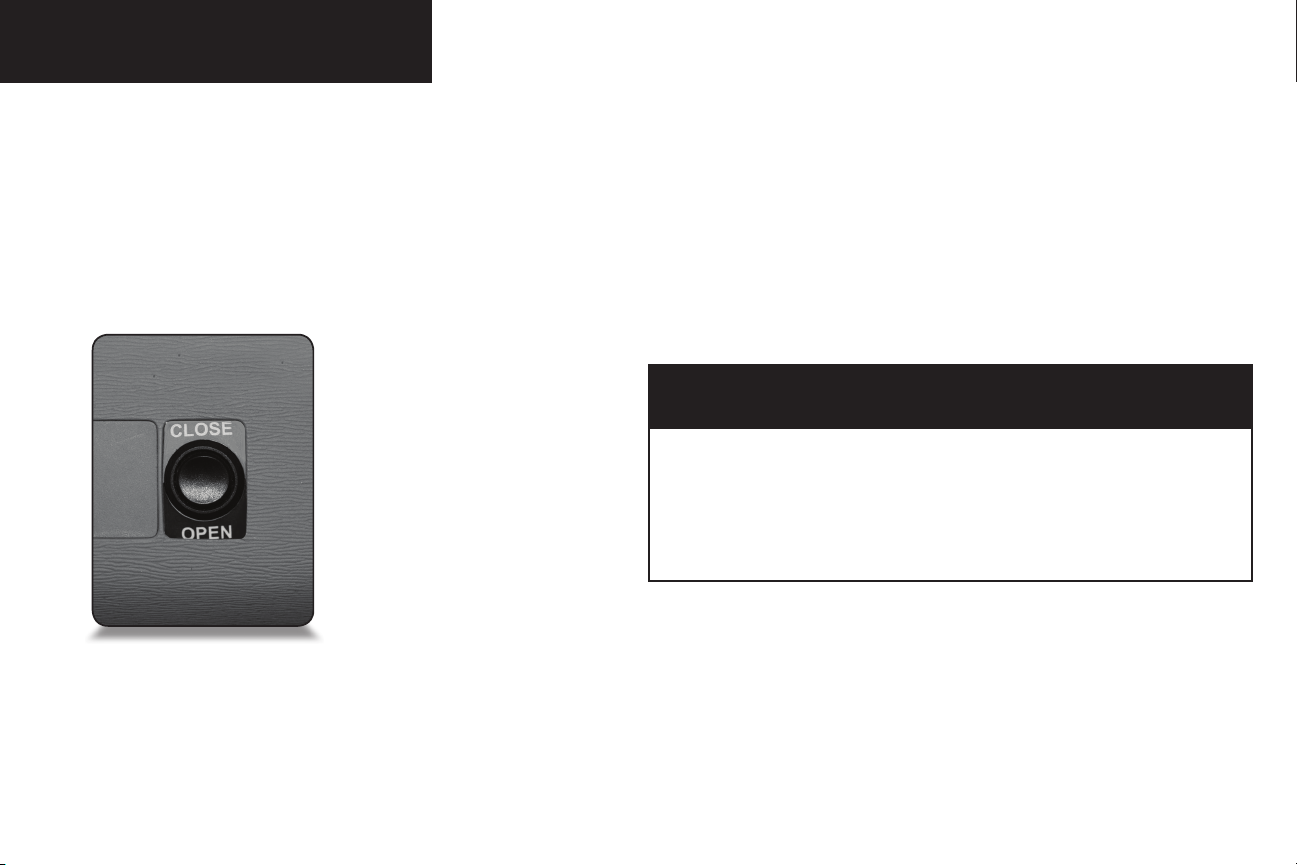
Open Function
Pressing and holding button 1 will open the
rear door and deploy the ramp. Releasing the
button will halt the ramp opening and can be
moved manually if desired.
Close Function
Pressing and holding button 2 will retract the
ramp and close the rear door. Releasing the
button will halt the ramp closing and can be
moved manually if desired.
Keyless Entry Transmitter
REMOTE KEYLESS ENTRY
3
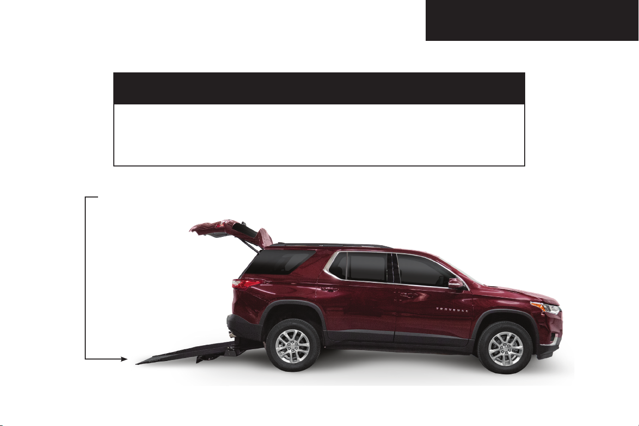
Open Function*
Pressing and holding button 1 will deploy the
ramp. Releasing the button will halt the ramp
opening and can be moved manually if desired.
Close Function*
Pressing and holding button 2 will retract the
ramp. Releasing the button will halt the ramp
closing and can be moved manually if desired.
Keyless Entry Transmitter
CAUTION: Be certain to release button after
ramp completely deploys. Failure to do so may
result in damage to ramp components.
*If factory equipped with automatic rear hatch,
use OEM remote to open/close.