8
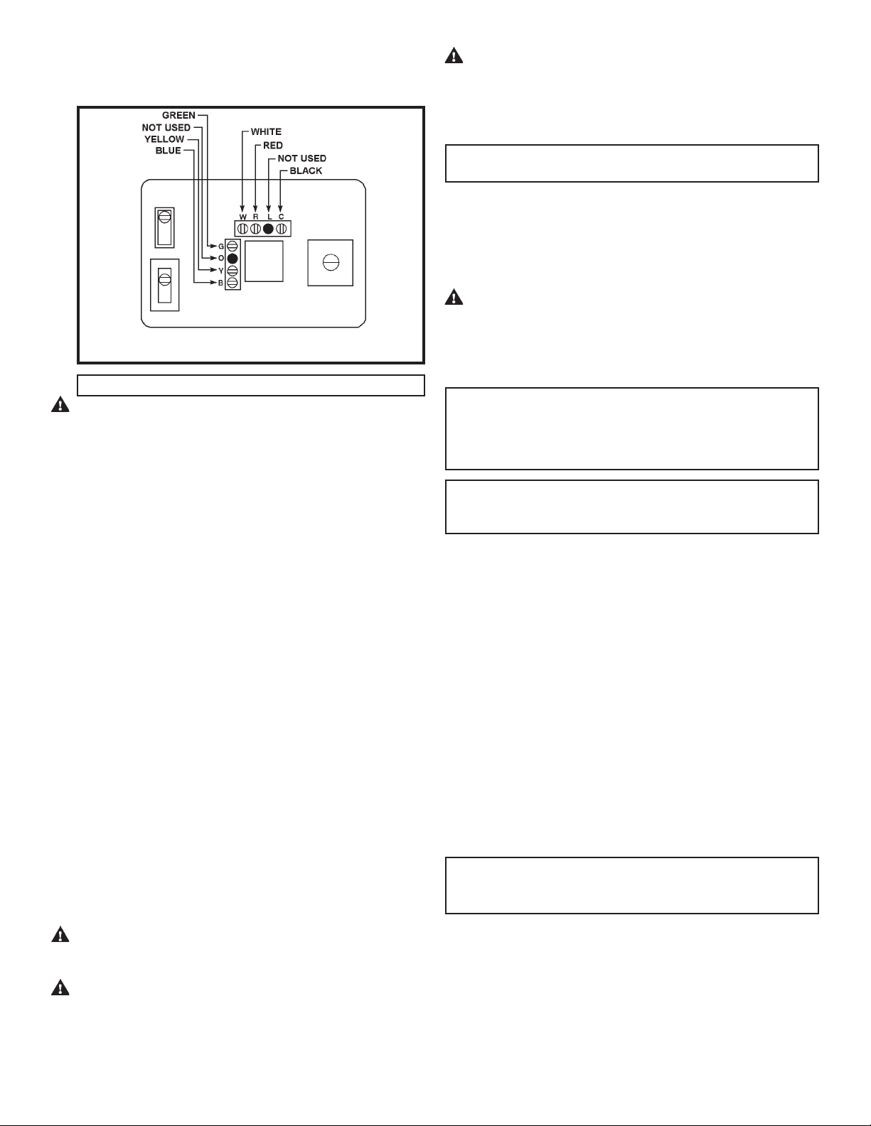
Figure 17 — Terminal and Switch Location
WARNING: Do not vent refrigerant to atmosphere. Recover all
refrigerantbeforesystemrepairorfinalunitdisposaltoavoidpersonalinjury
or death. Use all service ports and open all flow-control devices.
X. MAINTENANCE
NOTE: ItisrecommendedthattheVert-I-Pakbeinspectedandserviced
on an annual basis by a qualified technician.
If you perform maintenance on the unit yourself, remember that certain
mechanical and electrical skills, plus specialized tools are required to
properly perform maintenance. Personal injury or death may result if you
areNOTproperly trained. You should callyourinstalling dealer if youare
uncertain about your ability to perform maintenance.
WARNING: Electrical shock hazard. Turn OFF power to the system
before performing any maintenance or removing panels. Failure to do so
can result in personal injury and/or death.
A. Filters
NOTE:Dirtyfiltersarethemostcommoncauseofinadequateheatingand
cooling performance.
• Inspect filters monthly
• Replace disposable type filters before they become clogged
• Use water and mild detergent to clean washable type filters
NOTE: Some filters are marked with an arrow to indicate the proper
direction of air flow through the filter. The arrow MUST point in the
direction of air flow.
XI. INSTALLATION - FINAL CHECKLIST
1. Check to see if all duct work is sealed to unit for an airtight fit.
2. Insure that the condensate drain line is installed and run to an
appropriate disposal site.
3. Make sure the circuit breakers inside the unit are ON.
4. Insure that the thermostat is level and properly installed. Heat
anticipator indicator is set to the correct setting.
5. Test run in Heating, Cooling, and Emergency Heat mode as follows:
a. Set fan control to ON. If fan runs, return control to AUTO setting.
This verifies fan is working properly.
b. Set system control from OFF to COOL. Lower temperature
selector to 50°F or lower. The compressor should energize and
cool air should flow from room registers. Once cooling test is
complete, return system control to OFF setting. Wait 5 minutes.
c. SetsystemcontroltoHEATandraisetemperatureselectorto80°F
orhigher. Compressorshouldenergize,andwarmairshouldflow
from room registers.
d. Set system control to EM HEAT (Emergency Heat). Compressor
shouldturnoffandwarmairshouldcontinuetoflowfromregisters.
NOTE:DuringEMHEAToperation,temperatureofairflowingfromroom
registersmaybeslightlywarmerthanduringnormalHEATmodeoperation.
7. LeavebothInstallationManualandUsersManualwithowneroruser
of equipment.
8. After 72 hours of operation, the unit will achieve full rated operating
performance.
NOTE: Do not connect any unused thermostat cable wires.
CAUTION: Recheck wiring color code schedule to be certain proper
terminals are connected before applying power. Improper wiring or
installation may damage thermostat.
VIII. CONDENSATE DRAIN LINE
The condensate drain exits the unit just above floor level at the right side
front corner of the unit. The condensate drain line is already internally
trapped therefore, no external condensate trap is required.
Installacondensatedrainlineofthesamesizeasthedrainfittingontheunit.
PVCplasticpipe(3/4in.I.D.)makesanidealcondensateline(iflocalcodes
allow).
Run condensate drain line from unit to floor drain or outside perimeter of
building per local codes.
Thecondensatelinemusthaveaminimumdropof1/4"perrunningfootas
itleavestheunit. Whenahorizontalrunof15ft.orlongerisrequired,itmay
benecessarytoinstallaventteeinthedrainlineneartheunitorusealarger
diameter drain line. This is to eliminate air trapping and allow proper
condensate drainage.
Heatpumpsgeneratecondensateduringbothcoolingandheatingmodes.
Condensatedrainlinemustbeprotectedfromfreezingtopreventcondensate
from backing up in unit during freezing outdoor conditions.
IX. REFRIGERANT
The unit is pre-charged at the factory to the correct operating charge and
shouldnotrequireadjustment. However,shouldanadjustmentberequired
or if the unit requires service, adhere to the following precautions.
WARNING: Gageportsareequippedwithschradervalves. Toprevent
personalinjury,wearsafetyglassesandgloveswhenhandlingrefrigerant.
CAUTION: Compressordamagemayoccurifsystemisovercharged.
See unit serial tag for amount and type of refrigerant.
C. Wire Thermostat Cable to Unit Terminal Strip
Attach thermostat wires to low-voltage terminal block on left side of
control box in locations indicated in Figure 12.