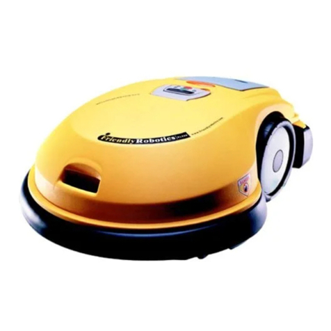
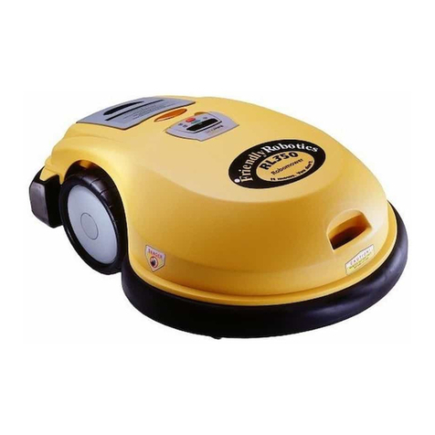
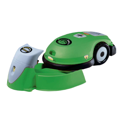
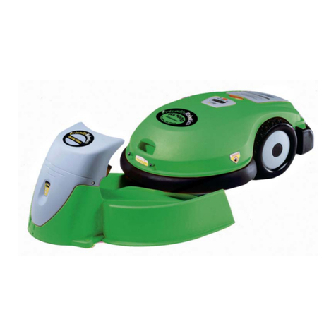
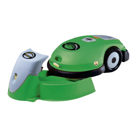
Friendly Robotics RL500 Operation manual

i
This document is subject to change without notice.
Friendly Robotics makes no warranty of any kind with regard to this material, including, but not limited to, the implied warranties of
merchantability and fitness for a particular purpose. Friendly Robotics shall not be liable for errors contained herein or for incidental or
consequential damages in connection with the furnishing, performance, or use of this material.
© Friendly Robotics, 2000-C. All rights reserved. No part of this document may be photocopied, reproduced, or translated to another language
without the prior written consent of Friendly Robotics.
This book was carefully prepared. However, the company does not bear responsibility for mistakes or misunderstandings, and the company
shall not bear responsibility for damage resulting from faulty instructions in this manual. The company reserves the right to introduce changes
in the product and/or this manual without prior notification.
All rights reserved to Friendly Robotics.
RL500 is a registered trademark of Friendly Robotics.
All other trademarks are the property of their respective owners.
CE Approved. (European Common Market UL equivalent)
Notes and Cautions
Throughout this guide, there may be blocks of text printed in italic type. These blocks are notes and/or caution notices. They
are used as follows:
NOTE: A Note indicates important information that helps you make better use of your RL500.
Tip: A Tip indicates useful hints or suggestions for smoother operation and care of your RL500.
A Caution indicates important safety information, tips or suggestions for proper handling of your robotic
lawnmower.
Printed in U.S.A
Updated: MAY 2000
How It Works
The perimeter wire installed at the lawn edge creates a virtual wall around the area(s) to be
mowed, flower beds and low obstacles. Your RL500 robotic lawnmower senses this virtual wall
as it approaches it and stays within the area(s) to be mowed. If the perimeter wire is cut or
damaged, the unit will display a ‘No Wire Signal’ message, and will stop operating. When the
perimeter wire is correctly installed and the mower is used according to the instructions in this
manual, the mower will not venture outside the virtual wall (see illustration below). Only a single
wire is seen and recognized by the mower. The two wires that lay parallel and touching are not
noticed at all.
RL500 is a mulching mower. The grass is finely cut and inserted back into the lawn where it
improves soil quality-- no more bagging and tossing the cut grass!
Caution:
Virtual wall seen only by RL500
SMARTHOME.COM™ 1-800-SMART-HOME 949-221-9200 http://www.smarthome.com Order #3256

ii
Welcome...
…to the world of robotic lawnmowing with the RL500. Please follow the
instructions in this manual to insure the safest and most effective
operation of your unit. To help you get better acquainted with your
RL500, follow the steps below:
1. Watch the instructional video first--get to know the essentials.
2. Read this manual carefully.
3. Follow the simple installation and operation instructions.
4. Review the safety precautions (Chapter 9).
Please read and make sure you understand the safety precautions and warnings in this manual;
they are for your protection. Do not allow people and/or pets on the lawn when RL500 is in
operation.
Owner Operating Manual
RL500
Battery Pack
Carrying Handle
3 Mulching Blades
21” overall cut
Manual Controller
Operation/Warning
Light
Battery Pack
Location
Rear Wheel
Height Handle
Bumpers
(Tactile Sensors)
Unit Description
SMARTHOME.COM™ 1-800-SMART-HOME 949-221-9200 http://www.smarthome.com Order #3256

iii
Table of Contents
1 Perimeter Switch Installation ............................................................................1.1
Switch location, switch power requirements and mounting instructions.
2 Perimeter Wire Installation ................................................................................2.1
Wire layout, using the measuring stick, yard obstacles, and mowing multiple plots.
3 Activating RL500................................................................................................3.1
Setting the cutting height, charging RL500, and manual “driving.”
4 Manual Controller and Menu Options ..............................................................4.1
Lists the main keypad functions and describes the menu options
5 Charging RL500..................................................................................................51
Properly charging your unit.
6 Care and Maintenance ......................................................................................6.1
Normal care and maintenance of your RL500.
7 Manual Mowing ................................................................................................7.1
How to use your RL500 in the Manual Mode.
8 Safety Measurements ........................................................................................8.1
Safety measurements built into your RL500 unit.
9 Troubleshooting ................................................................................................9.1
What to do if your RL500 is not functioning properly.
10 Warnings and Operating Suggestions ............................................................10.1
Common sense operating procedures and safety precautions.
11 Technical Specifications & Accessories ............................................................11.1
SMARTHOME.COM™ 1-800-SMART-HOME 949-221-9200 http://www.smarthome.com Order #3256

iv
1. Installation Tools: (not included)
Hammer, Wire Cutters, Small Slotted
Screwdriver
2. Installation Video:
Installation and operation instructions
3. RoboRuler:
Used for setting the distance of the
perimeter wire from the lawn edge.
Notice the two settings: 1) at the lawn
edge and 2) against a wall or fence.
4. Pegs & Wire:
Used for securing the perimeter wire
to lawn edges and around obstacles.
Think of it as a virtual wall for your
RL500.
5. Perimeter Switch:
Activates the perimeter wire, which
defines the area in which RL500 will
operate. (3 “C” batteries included)
6. Perimeter Switch Mounting Stake
For separate plot designation
7. Wire Connectors
For splicing wires
8. Fast Connectors
For separate plot installation
RL500
Battery Pack
4.
3.
5. 6.
7.
8.
2.
1.
What’s in the Box
SMARTHOME.COM™ 1-800-SMART-HOME 949-221-9200 http://www.smarthome.com Order #3256

1.1
1.1 Perimeter Switch Location
Choose a location for the perimeter switch that is away from children’s reach and
sheltered from rain, sun, and sprinkler systems.
Tip: The garage inner wall is an ideal place to mount the perimeter switch.
1.2 Power Requirements
Open the perimeter switch box and insert 3 “C” batteries as shown (fig.1-1). Alkaline
batteries recommended.
1.3 Mounting the Perimeter Switch
Mount the perimeter switch on a wall using two (2) small screws.
Chapter 1 - Perimeter Switch Installation
Fig. 1-1
Chapter One
Perimeter wire
Fast Connector
Wires from
lawn
SMARTHOME.COM™ 1-800-SMART-HOME 949-221-9200 http://www.smarthome.com Order #3256

2.1 Perimeter Wire Starting Point
Tear out perforated center piece on wire box. Find end of wire and pull out. Do not
remove wire spool from the box. Starting at the perimeter switch location, uncoil the
wire and lay it out on the lawn.
2.2 Securing Ground Pegs and Wire
Using the plastic pegs and the RoboRuler provided in the installation kit, secure the
wire around the lawn’s edge starting with the corners of the yard. Secure the wire
between corners as needed, making sure the wire is taut. Also make sure the pegs
and wire are flush with, or slightly below, ground level.
Note: No need to bury the wire. The grass will grow over and cover it.
Tip: If the ground is very dry, you may want to water the lawn slightly before staking the wire.
2.3 Securing the Perimeter Wire
Add pegs wherever the wire is raised above the grass (fig.2-1).
2.4 Using the RoboRuler™
There are two measurements on the RoboRuler. The shorter distance is used for a
lawn edge without obstacles or extreme inclines or declines (fig. 2-2). The longer
distance is for lawn edges bordered by walls, fences, rocks, flower beds or height
differences between the lawn’s edge and a sidewalk or street (fig. 2-3).
Chapter Two
2.1
Fig. 2-3
Fig. 2-2
Chapter 2 - Perimeter Wire Installation
Pegs added after the
initial laying of wire
Fig. 2-1
Wire
Perimeter wire
positioning
Sales: 1-877-404-7626 Support: 1-877-669-2687
SMARTHOME.COM™ 1-800-SMART-HOME 949-221-9200 http://www.smarthome.com Order #3256

Chapter Two
2.2
2.5 Corners and Sharp Turns
Avoid creating corners sharper than 90°. Sharp corners may cause RL500 to lose track
of the wire. Adjust the corners as needed, (fig. 2-4). making all corners greater than
90°. The sharp corner area, which is not wired, will be mowed manually.
2.6 Lawn Contours
Indentations along the edge or border of the lawn which are less than five feet wide
should be wired straight across the opening, (fig. 2-5).
2.7 Defining Lawn Obstacles - Perimeter Islands
Flower beds, ponds, young trees, and any object on the lawn lower than six inches or
too soft to be noticed by RL500’s bumper sensors, should be protected with a
perimeter wire looped around them. This is called a perimeter island. To create a
perimeter island, take the wire from the near edge and set it around the obstacle.
This creates a double wire (one leading from the edge, one going to the edge). The
sides of the double wire should be parallel and touching, so there is not a gap
between them. Unlike a single wire, RL500 does not recognize a double wire and will
mow over it. It will not enter the wired area around the obstacle.
Note: Use this solution as well on slanted trees, branches or roots sticking out, or any other obstacle
which may scratch the RL500 or cause blade damage.
Note: For illustration purposes, the lengths of wire leading to the perimeter island appear to have space
between them. This is not the case-- these wires must be parallel and touching for the RL500 to function
properly. Secure them to the ground using the same pegs.
Note: The distance from the perimeter wire to the island wire must be greater than 5 feet (fig. 2-6). If an
obstacle is less than 7 feet from the lawn edge or wall, leave it outside of the wired area (fig. 2-7).
Fig. 2-4
Lawn
Fig. 2-5
Lawn
Sharp corner
avoided
Mounted
Perimeter
Switch
Mounted
Perimeter
Switch
Incorrect
corner layout
Correct
corner layout
Chapter 2 - Perimeter Wire Installation (cont’d)
SMARTHOME.COM™ 1-800-SMART-HOME 949-221-9200 http://www.smarthome.com Order #3256

2.8 Terminating Perimeter Wire
After laying the perimeter wire, attach the two wire ends together and connect them
to the perimeter switch connector, making sure the wire from the switch to the
ground is taut (fig. 2-8).
Note: To connect the wires to the switch connector, strip a 1/4 inch of insulation from each wire end and
insert one end into each hole of the connector (no polarity). Tighten the screws.
Chapter Two
2.3
Fig. 2-6
Flower Bed
Lawn
Distance from
perimeter wire
to island wire
must be greater
than 5 feet.
Two wires parallel
and touching
Fig. 2-7
Flower Bed
Tree Lawn
Distance
between
obstacle and
lawn edge is
less than 7 ft.
Mounted
Perimeter
Switch
Mounted
Perimeter
Switch
}
Chapter 2 - Perimeter Wire Installation (cont’d)
Fig. 2-8
Two wires parallel
and touching
Flower Bed Closed perimeter
wire loop
Mounted
Perimeter
Switch
Sales: 1-877-404-7626 Support: 1-877-669-2687
Perimeter Island
SMARTHOME.COM™ 1-800-SMART-HOME 949-221-9200 http://www.smarthome.com Order #3256

2.9 Checking Your Connections
Press the ON button of the perimeter switch. The ON light will blink if all connections
are fine. The “Wire Disconnected” light will blink if there is any breakage in the wire
or a bad connection (fig. 2-9). Check all connections and try again.
2.10 Sloping Lawns
Leave slopes greater than 15° out of the perimeter wire area. These slopes are mowed
using the manual mode (fig. 2-10).
2.11 Multiple Mowing Plots
If you have more than one plot to mow, it is easy to set up separate perimeter areas.
Two wires attached together can lead from one plot to another to form a continuous
loop (fig. 2-11) and (fig. 2-12) and receive power from the same perimeter switch. The
distance between two adjacent plots should be greater than 6 feet (1.8 m.).
Note: For illustration purposes, the lengths of wire leading to the perimeter island and between plots
appear to have space between them. This is not the case-- these wires must be parallel and touching for
the RL500 to function properly.
Chapter Two
2.4
Fig. 2-9
“ON” indicator
“Wire Disconnected”
indicator
“Replace Batteries”
indicator
Chapter 2 - Perimeter Wire Installation (cont’d)
Fig. 2-10
Perimeter wire
Relatively
level lawn
Slope greater
than 15°
Fig. 2-11
B
A
Plot
Plot
Use concrete expansion joints
or steps to hide the perimeter wire
when connecting multiple plots.
SMARTHOME.COM™ 1-800-SMART-HOME 949-221-9200 http://www.smarthome.com Order #3256

Chapter Two
2.5
Tip: When there is not a direct approach from the perimeter switch, use concrete expansion joints in
driveways, sidewalks, flower beds or steps to hide the perimeter wire. Make sure the wire is securely
pegged or anchored to the surface. The distance between adjacent plots should be greater than 5 ft.
2.12 Alternate Perimeter Wire Layouts
Another solution for multiple plots is installing each plot separately (fig. 2-13). Wire
each plot and move the perimeter switch from plot to plot, mounting it on its special
plastic stake (fig. 2-14). Hold the mounting stake erect and drive it into the ground up
to the appropriate mark. Make sure it is at least 3 feet (1m.) from the perimeter wire,
so it will not be touched by RL500. The wires leading to the perimeter switch should
be touching and taut. The ends of the plot wires should be inserted into a fast
connector (one wire per hole). This fast connector can then be joined to the fast
connector on the perimeter switch.
Chapter 2 - Perimeter Wire Installation (cont’d)
Back Yard
Front Yard
HouseGarage
Fig. 2-13
Fig. 2-14
Perimeter switch
on mounting stake
Wires attached
Fast Connector
Fig. 2-12
Plot A
Plot B
Plot C
Garage
Sales: 1-877-404-7626 Support: 1-877-669-2687
Connecting Multiple Plots
SMARTHOME.COM™ 1-800-SMART-HOME 949-221-9200 http://www.smarthome.com Order #3256

3.1 Setting the Cutting Height
Raise RL500 to the height of cut needed for your grass condition. If your grass is
high, raise RL500 to its highest position. The front wheel has six levels of adjustment
and the rear wheel has three levels of adjustment.
Note: Unit generally ships in lowest settings for both front and rear wheels. On first operation, do not use
on lowest setting, as it may scalp the lawn.
3.2 Rear Wheel/Ground Clearance Adjustment
Located in the battery compartment, rear wheel height is set by pulling out tab (A)
and sliding up or down (B). (fig. 3-1).
Note: Unless your lawn is smooth and flat, it is recommended to operate your unit using the highest
ground clearance setting, for better maneuverability.
3.3 Front Wheel/Cutting Height Adjustment
Take out the battery pack, raise RL500’s front end (fig. 3-2), and rotate the wheel base
(fig. 3-3). Each “click” represents one notch of height.
Note: For low mowing, adjust rear and front wheel heights. If unit loses mobility, raise rear wheels and
lower front wheel, or consider purchasing a Low Cut Blade (available as a separate accessory).
Chapter 3 - Activating RL500
Fig. 3-2
Fig. 3-1
Fig. 3-3
Lower
Raise
Note: To engage
highest setting,
pull out (A) and
push downward
(B).
Chapter Three
3.1
B
A
SMARTHOME.COM™ 1-800-SMART-HOME 949-221-9200 http://www.smarthome.com Order #3256

3.4 RL500 Battery Pack
Using the battery pack handle, insert the battery pack into its opening in RL500.
RL500 will immediately switch ON audio will sound). (fig. 3-4)
3.5 Set Geo/’Calibration’
On first operation only: Press the green button. The display will change to read 'Set
GEO Location.' The bottom display line will read 'Location.' Leaving the manual
controller in its cradle, press the green button for 'Location.' The display should read,
'Not set!' Scroll to your country and press the green button to accept it. Press the 'C'
button to get back to the main menu and press the green button to start mowing.
Note: This Geographic Location setting is needed for the mower's compass accuracy. This procedure is
done only once, upon demand from the mower and is not needed for every operation or on every plot.
This geographic compass orientation is accurate within a hundred mile radius of your area.
If setting the Geographic Location is not accurate enough for your yard, a 'Calibration
req.' message will appear. The bottom display line should read, 'Calibrate.' Press
green button. The display will change to 'DK Calibration,' and the bottom display line
will say 'confirm.' Press green button again, and the mower will turn around twice to
orient its compass to your yard. (The perimeter switch and wire are not part of this
calibration and may be on or off). After finishing the compass (DK) calibration, the
display will show a score. If the calibration was not successful, the display will say
'Retry elsewhere.' Drive the mower to another flat area on your lawn and repeat the
procedure. This may take several tries.
Note: A bumpy surface makes calibration difficult and may result in 'Retry elsewhere' messages.
Fig. 3-4
Chapter Three
3.2
Chapter 3 - Activating RL500 (cont’d)
Sales: 1-877-404-7626 Support: 1-877-669-2687
SMARTHOME.COM™ 1-800-SMART-HOME 949-221-9200 http://www.smarthome.com Order #3256

3.6 Positioning Your RL500 for Operation
Drive RL500 to your lawn and position it inside the perimeter wire (approx. 3 feet
(1m.) from the wire) aimed to the left (counter-clockwise) and not aimed at a corner
(fig. 3-5) .
3.7 Reinserting Manual Controller
Feeding the cord into the bottom of the holder, return the manual controller to its
cradle and pivot down. The controller should be flush with the unit’s surface.
Note: Once in place, the manual controller becomes the automatic control panel.
3.8 Perimeter Switch Power
Press the “ON” button found on the face of the switch.
Note: It will automatically shut off after 3 hours.
3.9 Operating
Press the green button on the control panel. A ‘Warming Up’ message will appear for a few
seconds, audio will sound. RL500 will begin to move forward, towards the perimeter wire.
After positioning itself on the wire, RL500 will mow the border one to two times. When the
border is completely mowed, RL500 will turn left into the lawn and begin to mow inside the
perimeter wire until the end of its designated work time (fig. 3-6).
Note: ‘Skip edge’ will appear under the ‘Warming Up’ message. To bypass mowing the edge of the lawn
and go straight to mowing the main area inside the wire, simply press the green button while ‘Warming
Up’ is still displayed.
Chapter Three
3.3
Chapter 3 - Activating RL500 (cont’d)
Fig. 3-5
Perimeter Wire
Lawn
Fig. 3-6
SMARTHOME.COM™ 1-800-SMART-HOME 949-221-9200 http://www.smarthome.com Order #3256

3.10 Setting the Work Time
Take the manual controller out of its cradle and press the green button for ‘Settings,’
then scroll to ‘Work Time.’ Press the green button, scroll to the amount of time
desired, and press the green button again to accept the new time setting.
Note: A ‘Max’ setting will cause the RL500 to operate until the batteries run down, with enough power
remaining to drive the RL500 to the charging location. A ‘None’ setting will cause the RL500 to have
zero operating time.
Note: If you choose not to set the work time, RL500 will use the Work Time default setting of 2 hours (fig.
3-7).
3.11 How to determine ‘Work Time’ for a Plot
As a rule of thumb, each one hour of operation will mow 1000 square feet (100 sq.m.) A
full 2.5 hours of operation will mow 2500 sq.ft. --roughly the size of a tennis court. A few
typical examples:
A large size plot roughly the size of two tennis courts--5000 sq.ft (500 sq.m.)--will need
two consecutive operations of the full 2.5 hours of 'Work time'. This means your RL500
operates for 2.5 hours, recharges, and operates again for 2.5 hours on the following day.
Note: The first operation will leave patches of uncut grass. These patches will be mowed in the second
mowing cycle, regardless of the mower's starting point. To keep the lawn well groomed, it is best to
operate the mower few times a week. A larger plot may need three consecutive operations and follow-ups
every other day to achieve an evenly-groomed look.
A medium size plot roughly the size of a tennis court--2500 sq.ft (250 sq.m.)--will need
one operation for the full 2.5 hours of 'Work time.' This plot size will probably require
mowing every 3-5 days, depending on season, rain, grass type, etc.
Note: A larger plot will need another, shorter operation after the battery has been fully recharged.
A small size plot--1000 sq.ft (100 sq.m.)--will need approximately 1 hour of 'Work Time.'
Repeat every 3-5 days as needed.
Many factors, such as grass type, length, humidity, slopes, obstacles etc., affect the 'Work
Time.' Keep trying until you become an expert in setting the right 'Work Time' for your
lawn. If you choose not to set a 'Work Time,' the RL500 will default to 2.5 hours on any
given lawn. However, avoid extreme disproportion, such as 2.5 hours 'Work Time' for a
plot smaller than 1000 sq.ft (100 sq.m.). This may cause grass condition to deteriorate
due to an "ironing" effect, caused by the wheels driving on it for an unnecessarily long
time.
Note: An extra battery pack with its own charger is a good solution for users who want to mow a large
plot (in some cases the whole lawn) in the same day. Replacing the battery pack after the first operation
will give you up to 5 hours of total operation time.
Chapter Three
3.4
Chapter 3 - Activating RL500 (cont’d)
Fig. 3-7
Sales: 1-877-404-7626 Support: 1-877-669-2687
SMARTHOME.COM™ 1-800-SMART-HOME 949-221-9200 http://www.smarthome.com Order #3256

4.1 Manual Controller and Main Keypad Functions (fig. 4-1)
Place your finger in the manual controller indentation and tilt its drawer up, in order
to take it out.
4.2 Menu Options
When you lift the manual controller, the display will show 'Manual' on the first line
and 'Settings' on the second line. Pressing the green button will get you into the
'Settings' menu. Scroll through the menu and you will see the following default
option settings: 'Sound On,' 'Child Guard Off,' 'Mowing On,' 'GEO Location,'
'Language,' 'Work Time,' 'Service Key,' 'Diagnostics,' and back to 'Sound On.' It is a
repeating loop of menu options that can be scrolled up or down.
Multi-Function Green Button: Use it to 'Set' or 'OK' any option choices. Pressing the
green button will accept the setting located on the second line of the display
window.
Changing a Setting: Changing the settings is easy. On the second line of each menu
option you have a 'Set' option--right above the green button. Choosing 'Set' by
pressing this button will allow you to change the selected setting by scrolling. After
scrolling to a new choice, the second display line will read 'OK.' Press the green
button to 'OK' (enter) your new choice. Press the 'C' button on the manual controller
to return to a higher sub-menu. Wherever you are, if you press 'C' a few times, you
will arrive at the original 'Manual' message on the first line and 'Settings' on the
second line.
These are the menu options within 'Settings' and how you may change with them:
'Settings'--press the green button to enter this menu.
'Sound On'--choose 'Set,' scroll to 'off,' OK your selection. The display will change to
'Sound off.' RL500 will operate without audio.
'Child Guard Off'--'Set,' scroll to 'on,' OK your selection. The display will change to
'Keys Locked.' Touch any key, and the display will show the sequence of keys to press
to enable operation. Press the keys in sequence and a one minute window will allow
you to access all keys normally. If no buttons pressed within the one minute, the
display will return to 'Keys Locked.'
Chapter Four
4.1
Chapter 4 - Manual Controller and Menu Options
Fig. 4-1
1. Display Window
2. ‘Manual Mow’ Button
Used in manual mowing sequence
3. Drive Speeds
>> Fast, > Slow: Changes drive
speed
4. Directional Pad
Directs RL500 while steering
manually
5. Cancel
Go to previous menu
6. Green Button/’Smart Key’
Used for operating RL500 in main
modes, serves as an “enter” key
for settings and menu choices
7. Stop
Stops RL500 at any stage of its
operation
8. Scroll Arrows
Used for scrolling through menu
1
2
3
4
5
6
7
8
SMARTHOME.COM™ 1-800-SMART-HOME 949-221-9200 http://www.smarthome.com Order #3256

4.2
Chapter Four
Chapter 4 - Manual Controller and Menu Options (cont’d)
Sales: 1-877-404-7626 Support: 1-877-669-2687
'Mowing On'--'Set,' scroll to 'off,' OK the choice. The display will change to 'Mowing
off.' RL500 will move, but will not cut. This mode may be used on the first operation
with a newly set perimeter wire, in order to check its distance from the lawn edge,
etc. This way if the wire is loose or raised above the grass, the blades will not cut it.
'GEO Location'--Choose 'Set.' The display will change to 'Not Set!' with three arrows
pointing from the right side of the display. Scroll to your country, OK the choice, and
the display will change to your country with three arrows pointing at it (meaning this
is the present choice). If you neglect to set this location the mower will not move in
automatic mode, and will display 'Set GEO Location' to remind you.
'Language'--Choose 'Set.' The display will change to 'English' with three arrows
pointing from the right side of the display. Scroll to one of the nine languages, OK
the choice, and the display will change to the chosen language with three arrows
pointing at it (meaning this is the present choice). The menu will now appear in the
new language.
Note: To return to English, press 'C' a few times to get to the first 'Settings' line (which will be in a
strange language), press green button, scroll down four times, press green button, scroll until you see
'English,' press the green button, and you are back to a language you can understand. What a relief...
'Work time'--Choose 'Set.' The display will change to 'Zone A 2:40.' Scroll to a new
value, OK your choice, and your newly set time will show in front of 'Zone A.' The
work time is set in increments of 20 minutes. You may also choose 'None' (will work
for zero minutes, or not at all) or 'Max' (until the batteries run down).
Service Key'--OK this option and the display will change to '00000' The first zero is
underlined and on the right side of the display, in brackets, is the number of
operations your mower has completed. The lower line of the display will say 'Next
Digit.' This option is used when you call a service representative to diagnose any
problem in your mower. You will need to tell the service representative the number of
operations (in the brackets) and he will give you a password. To insert the password,
scroll to the digit you want and select 'Next Digit.' The line underneath the zero will
move. When you select 'Next Digit' after the last digit, the display will show the 'Key
and 5 digits' you entered plus 'Confirm' on the bottom line. Select 'Confirm' and if
you entered it correctly the display will change to 'Diagnostics,' which is more
detailed than the one you normally use.
'Diagnostics'--OK this menu item to reach sub-menus of items you can diagnose. The
first choice is 'Wire Sensors.' OK this and the display will read 'Wait...' (bottom line
will read 'Advanced'). In a few seconds you will see the front sensors reading. Scroll,
and you get the rear sensors reading. You can scroll past the 'Wire sensors' option, to
see other diagnostic features: 'Direction keeper' (the compass), 'Front Wheel Sensor'
(the drop-off mechanism), 'Bumpers,' 'Software Version,' 'Total time' (this mower has
operated on automatic mowing), 'Buttons' (checking buttons response),and
'Miscellaneous' (battery voltage and temperatures).
SMARTHOME.COM™ 1-800-SMART-HOME 949-221-9200 http://www.smarthome.com Order #3256

5.1 “Charging” Procedure
Make sure the charger is plugged into a standard 110V household outlet. The
charging plug connects to RL500 at the manual controller base. Pivot it up on its
hinges (fig. 5-1), connect the charger plug and pivot it back to lie flush with the
surface. The display will read “Charging.” The display will read “Fully Charged” when
ready for operation.
Note: Operating RL500 prior to having a ‘Fully Charged’ message will reduce your battery life… trust us!
Note: RL500 should be charging at all times when not in use. Continuous charging does not harm the
batteries.
5.2 Winterizing
The following procedure is recommended for those households where the RL500 is
stored in a geographic location where regular winter temperatures often drop below
freezing:
1. Charge unit until ‘Fully Charged’ message is displayed.
2. Remove the battery and store outside the mower.
3. Repeat this process every two months.
4. If temperatures should drop below -4° F (-20° C), follow steps 1 through 3, and
store the battery in a warmer place.
5. RL500 should be charged at temperatures lower than 122° F (50° C), and higher
than 32° F (0° C). Exceeding these conditions, will cause a ‘Charging Problem’
message to be displayed, until the temperatures return to the the safe charging
range.
Chapter 5 - Charging
Fig. 5-1
Chapter Five
5.1
Charging
Plug
Charging
Socket
SMARTHOME.COM™ 1-800-SMART-HOME 949-221-9200 http://www.smarthome.com Order #3256

6.1 Mowing Deck and Blades Area
Prior to accessing the mowing deck area, stop RL500 and completely remove the
battery pack to switch it off. (fig. 6-1).
6.2 Cleaning RL500
Remove the battery pack and blades prior to cleaning the mowing deck area. To
clean RL500, lift to an upright position by using the carrying handle. Use a wet cloth
or soft brush to clean the mowing deck area and the wheels from accumulated grass
clippings.
Note: If unexpected showers may occur in your area, clear the drainage holes located on the bottom of
the of the battery compartment below the manual controller compartment.
Note: Do not put the RL500 upside down--you may damage the manual controller.
6.3 Improper Cleaning
Do not attempt to power-hose your RL500. Water could damage the unit’s
electronics.
6.4 Blade Replacement
RL500’s blades are easy to replace. Squeeze the plastic tabs at the base (A) of the
blade and pull toward you (B) (fig. 6-2). To put in a new blade, simply hold it by its
base and push it in, until a positive click is heard and felt. If a positive click is not
heard, remove blade and repeat procedure.
Caution: The blades are sharp! Use extreme care during replacement or cleaning. The use of heavy work
gloves is recommended when handling the blades.
Note: For lawn owners desiring a low grass height of 3/4” to 1-1/2” , a special blade is available
through your dealer or Friendly Robotics, 888-404-7626.
Chapter 6 - Care and Maintenance
Fig. 6-1
Chapter Six
6.1
Fig. 6-2
A
A
B
Sales: 1-877-404-7626 Support: 1-877-669-2687
SMARTHOME.COM™ 1-800-SMART-HOME 949-221-9200 http://www.smarthome.com Order #3256

7.1 Manual Mowing
Remove the manual controller from its cradle (fig. 7-1) and press the buttons in this
sequence: (1) press and hold down “C,” (2) then press and hold down “Mow,” until
the blades start (3) then release “C.” Maintain pressure on the “Mow” button while
manually mowing. Release it when you want to stop the blades. Maneuver the
mower using the Directional Pad. Repeat this sequence any time the blades are
stopped while manually mowing (e.g. when the RL500 has struck an obstacle with
the bumper or mow button is released).
Note: Always wear appropriate footwear and walk behind RL500 and keep a distance of at least 1 foot
(30 cm.) from RL500’s rear bumper.
Chapter 7 - Manual Mowing
Chapter Seven
7.1
STEP 1. With right thumb, press
and Hold ‘C’ Button
STEP 2. With left thumb, press
and Hold ‘Mow’ Button
until the blades start
STEP 3. Release ‘C’ Button
STEP 4. With right thumb, use
the Directional Pad to
maneuver the RL500
Note: Releasing the ‘Mow’ Button at any time
will stop the blades.
Fig. 7-1
24
3
1
SMARTHOME.COM™ 1-800-SMART-HOME 949-221-9200 http://www.smarthome.com Order #3256
Other manuals for RL500
2
Table of contents
Other Friendly Robotics Lawn Mower manuals

Friendly Robotics
Friendly Robotics Robomow RL1000 Instruction Manual

Friendly Robotics
Friendly Robotics Robomow RL350 Instruction Manual

Friendly Robotics
Friendly Robotics RL850 Instruction Manual

Friendly Robotics
Friendly Robotics robomower RL1000 Instruction Manual

Friendly Robotics
Friendly Robotics RL500 Instruction Manual

Friendly Robotics
Friendly Robotics Robomow RL1000 Instruction Manual

Friendly Robotics
Friendly Robotics robomower RL1000 User manual

Friendly Robotics
Friendly Robotics Robomow RL350 User manual

Friendly Robotics
Friendly Robotics robomower RL350 User manual

Friendly Robotics
Friendly Robotics RL500 Instruction Manual