FriendlyARM NanoPi NEO Plus2 User manual
Overview
Front
Back
NanoPi NEO Plus2
wiki.friendlyarm.com /wiki/index.php/NanoPi_NEO_Plus2
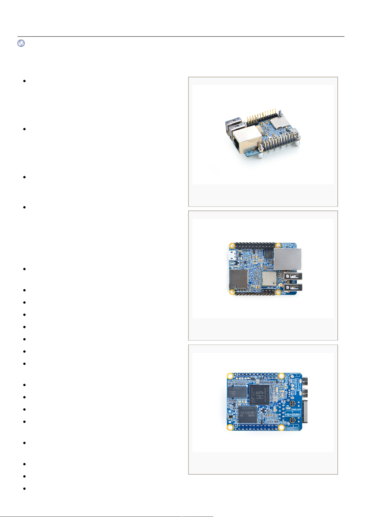
Introduction
The NanoPi NEO Plus2 is another Allwinner based
ARM board developed by FriendlyElec. It uses
Allwinner's 64-bit quad-core A53 SoC with hexa-
core Mali450 GPU and features 1GB of DDR3 RAM
and 8GB eMMC.
With a small size of only 40 x 52mm the NanoPi
NEO Plus2 has rich on-board resources: AP6212A
WiFi & Bluetooth module, Gbps Ethernet and two
USB hosts. It supports system-boot from a MicroSD
card.
The NanoPi NEO Plus2 has a carefully designed
power system and 6-layer PCB layout. These
features enhance the board's heat dissipation.
The NanoPi NEO Plus2 meets popular IOT
applications requirements for small size, high-speed
and large throughput data transmission and high
performance computing.
Hardware Spec
SoC: Allwinner H5,Quad-core 64-bit high-
performance Cortex A53
DDR3 RAM:1GB
Storage: 8GB eMMC
Network: Gbps Ethernet
WiFi: 802.11b/g/n
Bluetooth: 4.0 dual mode
USB Host: 2 x Independent USB Host
MicroSD Slot: 1 x Slot. It supports system booting
or is used to hold a storage card
Audio Input/Output: 5-Pin, 2.0mm pitch pin-header
MicroUSB: power input
Debug Serial: 4Pin, 2.54mm pitch pin-header
GPIO1:24Pin, 2.54mm pitch double-row pin-header
containing UART, SPI, I2C and IO
GPIO2:12Pin, 2.54mm pitch pin-header containing
USB, IR receiver,I2S and IO
Power Supply: DC 5V/2A
PCB Dimension: 40 x 52mm
PCB Layer: 6-Layer
1/13

Software Features
UbuntuCore
mainline kernel: Linux-4.x.y
UbuntuCore 16.04
64-bit OS
supports FriendlyElec’s BakeBit Kit
supports FriendlyElec’s NanoHAT OLED
pre-installed FriendlyElec’s NanoHAT Motor Python Library
pre-installed WiringPi for GPIO access
pre-installed RPi.GPIO for GPIO access
npi-config: system configuration utility for setting passwords, language, timezone, hostname, SSH and
auto-login.
networkmanager: a network utility to manage networking
auto-login with user account "pi" with access to npi-config
supports Gbps Ethernet
supports WiFi and Bluetooth
supports FriendlyElec's FA-CAM202 USB camera
supports audio recording and playing
Debian for NAS Dock
supports FriendlyElec’s NAS Dock
pre-installed OpenMediaVault
Diagram, Layout and Dimension
Layout
2/13
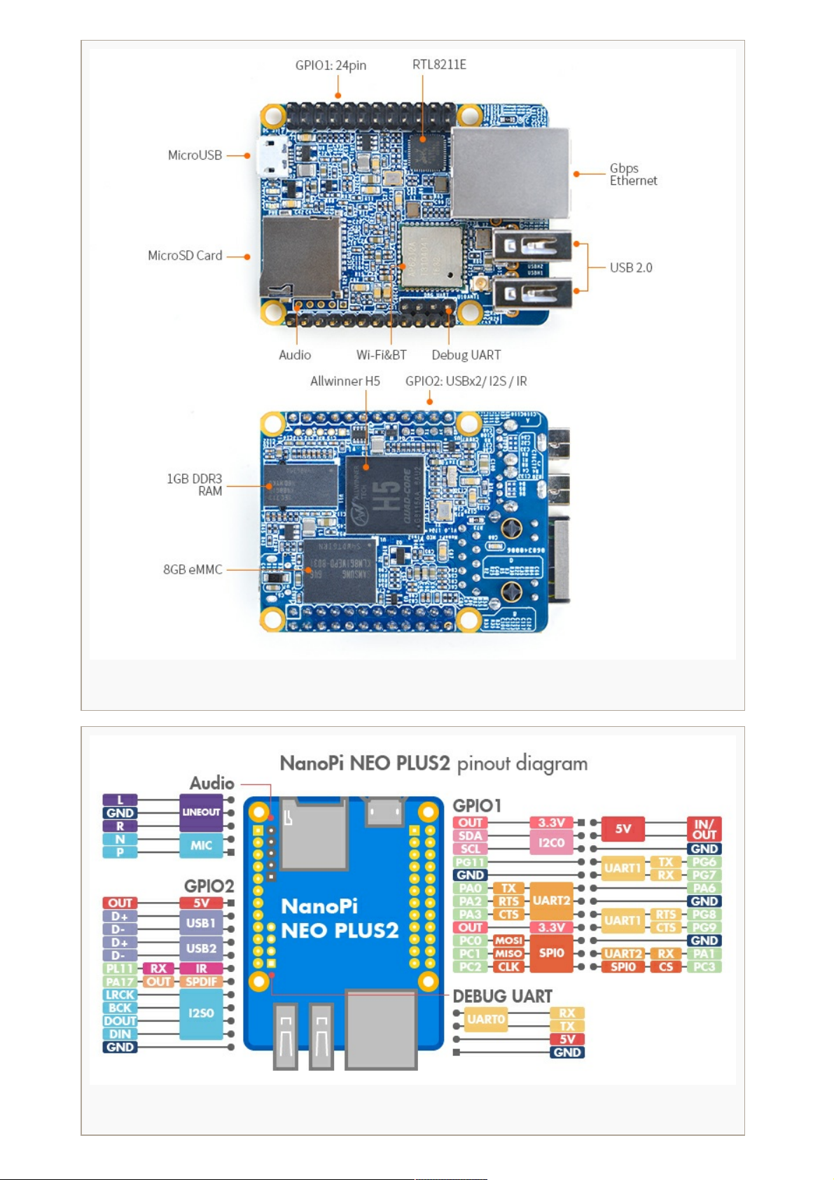
NanoPi NEO Plus2 Layout
pinout
3/13

GPIO Pin Description
Pin# Name Linux gpio Pin# Name Linux gpio
1 SYS_3.3V 2 VDD_5V
3 I2C0_SDA / GPIOA12 12 4 VDD_5V
5 I2C0_SCL / GPIOA11 11 6 GND
7 GPIOG11 203 8 UART1_TX / GPIOG6 198
9 GND 10 UART1_RX / GPIOG7 199
11 UART2_TX / GPIOA0 0 12 GPIOA6 6
13 UART2_RTS / GPIOA2 2 14 GND
15 UART2_CTS / GPIOA3 3 16 UART1_RTS / GPIOG8 200
17 SYS_3.3V 18 UART1_CTS / GPIOG9 201
19 SPI0_MOSI / GPIOC0 64 20 GND
21 SPI0_MISO / GPIOC1 65 22 UART2_RX / GPIOA1 1
23 SPI0_CLK / GPIOC2 66 24 SPI0_CS / GPIOC3 67
USB/Audio/IR Pin Description
NanoPi NEO Plus2
Pin# Name Description
1 VDD_5V 5V Power Out
2 USB-DP1 USB1 DP Signal
3 USB-DM1 USB1 DM Signal
4 USB-DP2 USB2 DP Signal
5 USB-DM2 USB2 DM Signal
6 GPIOL11 / IR-RX GPIOL11 or IR Receive
7 SPDIF-OUT / GPIOA17 GPIOA17 or SPDIF-OUT
8 PCM0_SYNC / I2S0_LRC I2S / PCM Sample Rate Clock/Sync
9 PCM0_CLK / I2S0_BCK I2S / PCM Sample Rate Clock
10 PCM0_DOUT / I2S0_SDOUT I2S / PCM Serial Data Output
11 PCM0_DIN / I2S0_SDIN I2S / PCM Serial Data Input
12 GND 0V
Audio
Pin# Name Description
4/13
DBG_UART
1 MICIN1P Microphone Positive Input
2 MICIN1N Microphone Negative Input
3 LINEOUTR LINE-OUT Right Channel Output
4 GND 0V
5 LINEOUTL LINE-OUT Left Channel Output
Debug Port((UART0))
Pin# Name
1 GND
2 VDD_5V
3 UART_TXD0 / GPIOA4
4 UART_RXD0 / GPIOA5 / PWM0
Note:
1. SYS_3.3V: 3.3V power output
2. VVDD_5V: 5V power input/output. The
input range is 4.7V ~ 5.6V
3. All pins are 3.3V, output current is 5mA
4. For more details refer to the document: NanoPi-NEO-Plus2-1704-Schematic.pdf
Dimensional Diagram
For more details refer to: [Dimensions_NanoPi-NEO-Plus2-1704]
Get Started
Essentials You Need
Before starting to use your NanoPi NEO Plus2 get the following items ready:
5/13
NanoPi NEO Plus2
microSD Card/TFCard: Class 10 or Above, minimum 8GB SDHC
microUSB power. A 5V/2A power is a must
A Host computer running Ubuntu 14.04 64 bit system
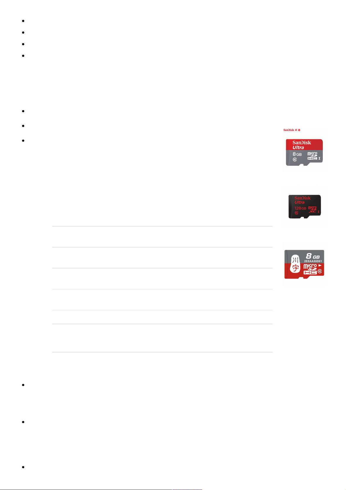
TF Cards We Tested
To make your NanoPi NEO Plus2 boot and run fast we highly recommend you use a Class10 8GB SDHC TF
card or a better one. The following cards are what we used in all our test cases presented here:
SanDisk TF 8G Class10 Micro/SD TF card:
SanDisk TF128G MicroSDXC TF 128G Class10 48MB/S:
川宇 8G C10 High Speed class10 micro SD card:
Make an Installation TF Card
Get Image Files
Visit this link download link to download image files(under the "official-ROMs" directory) and
the flashing utility(under the "tools" directory):
Image Files:
nanopi-neo-plus2_ubuntu-core-
xenial_4.x.y_YYYYMMDD.img.zip
Ubuntu-Core with Qt-Embedded
image file, kernel:Linux-4.x
nanopi-neo-plus2_debian-nas-
jessie_4.x.y_YYYYMMDD.img.zip
NAS image file, kernel:Linux-
4.x, for 1-bay NAS Dock
nanopi-neo-plus2_ubuntu-
oled_4.x.y_YYYYMMDD.img.zip
OLED image file, kernel:Linux-
4.x, for NanoHat OLED
nanopi-neo-
plus2_eflasher_4.x.y_YYYYMMDD.img.zip
eflasher image file,
kernel:Linux-4.x
Flash Utility:
win32diskimager.rar Windows utility for flashing
Debian image. Under Linux
users can use "dd"
Make Installation MicroSD Card
Extract the nanopi-neo-plus2_ubuntu-core-xenial_4.x.y_YYYYMMDD.img.zip and win32diskimager.rar.
Insert a MicroSD card(at least 8G) into a Windows PC and run the win32diskimager utility as
administrator. On the utility's main window select your card's drive, the wanted image file and click on
"write" to start flashing the card till it is done.
Insert this card into your NEO Plus2's MicroSD card slot and power on (with a 5V/2A power source). If the
blue LED blinks this indicates your NEO Plus2 has successfully booted.
Flash Image to eMMC
Extract the nanopi-neo-plus2_eflasher_4.x.y_YYYYMMDD.img.zip package and win32diskimager.rar.
6/13

Insert a MicroSD card(at least 8G) into a Windows PC and run the win32diskimager utility as
administrator. On the utility's main window select your SD card's drive, the wanted image file and click on
"write" to start flashing the MicroSD card.
Insert this card into your NEO Plus2 and power on (with a 5V/2A power source) the board. If the green
LED is on and blue LED is blinks it indicates your eflasher has started successfully.
Run the following command on a terminal:
$
eflasher
Select your wanted OS and type "yes" to start flashing. After it is done take off the card, reboot your board it will
boot from eMMC.
Work with Ubuntu-Core with Qt-Embedded
Run Ubuntu-Core with Qt-Embedded
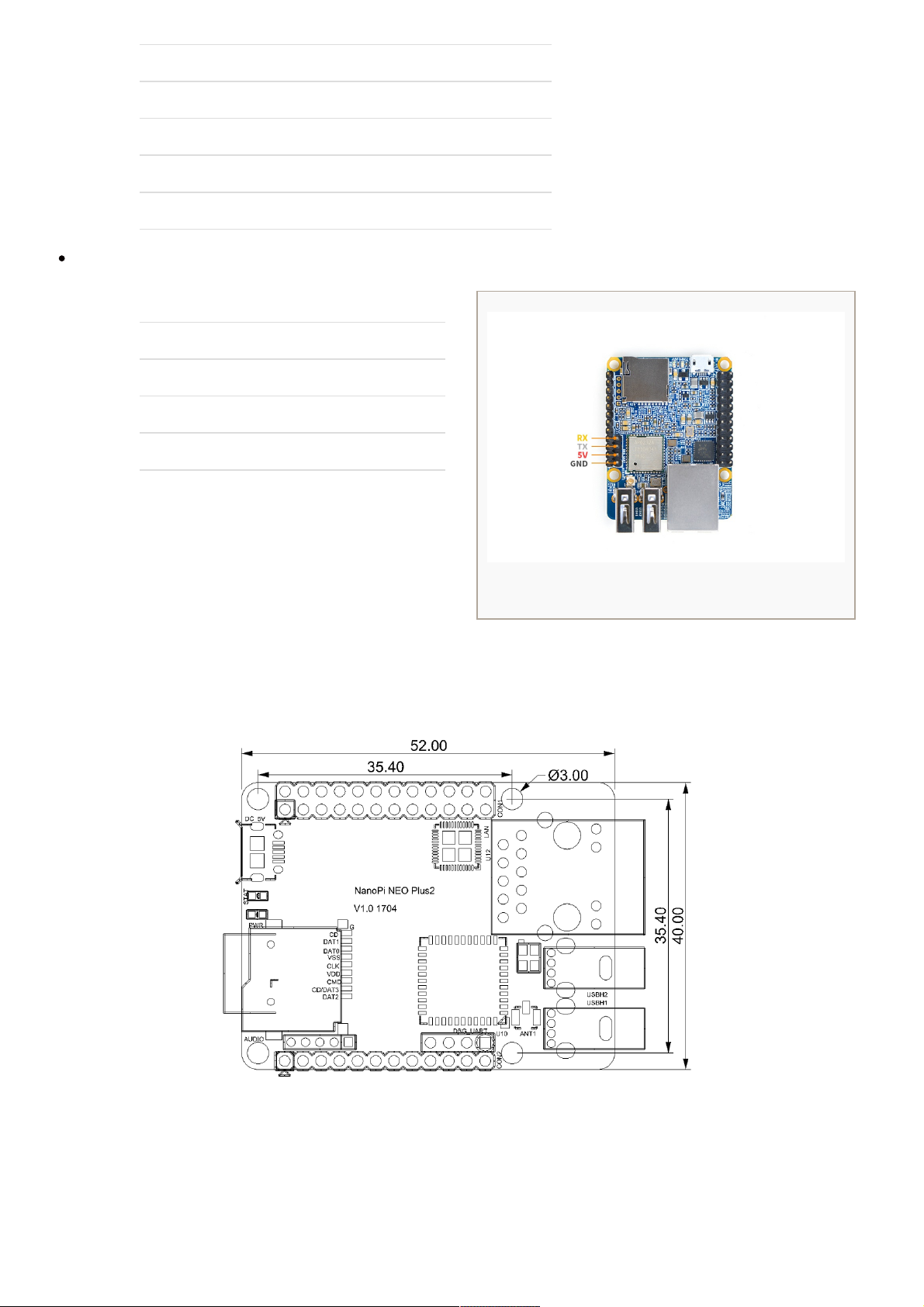
If you want to do kernel development you need to use a serial communication board, ie a PSU-ONECOM
board, which will allow you to operate the board via a serial terminal.Here is a setup where we connect a
NanoPi NEO Plus2 to a PC via the PSU-ONECOM and you can power on your NEO Plus2 from either the
PSU-ONECOM or its MicroUSB:
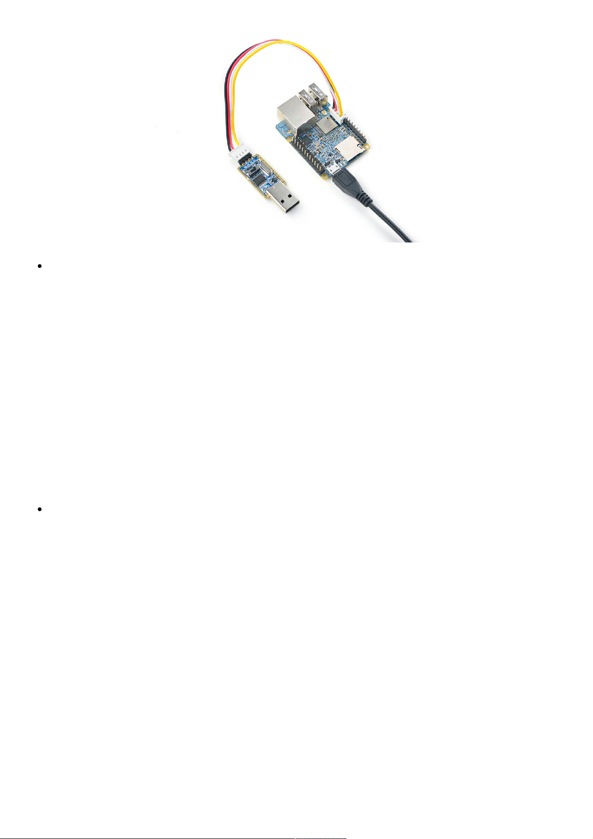
You can use a USB to Serial conversion board too. Make sure you use a 5V/2A power to power your NEO Plus2
from its MicroUSB port:
7/13
Default Login Account:
Regular User:
User Account:
pi
Password: pi
Root:
User Account:
root
Password: fa
By default pi logs in automatically. You can disable its auto-login by using "sudo npi-config".
Update Software Packages:
sudo apt-get
update
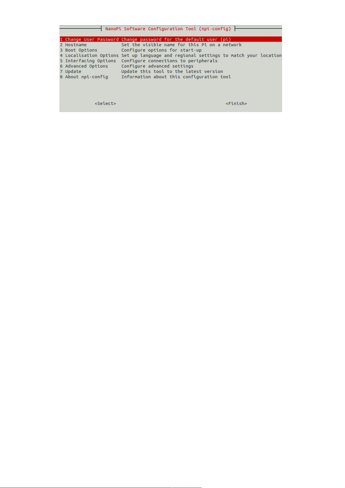
Configure System with npi-config
The npi-config is a commandline utility which can be used to initialize system configurations such as user
password, system language, time zone, Hostname, SSH switch , Auto login and etc. Type the following
command to run this utility.
$ sudo npi-
config
Here is how npi-config's GUI looks like:
8/13
Ethernet Connection
If the NanoPi NEO Plus2 is connected to a network via Ethernet before it is powered on it will automatically
obtain an IP after it is powered up. If it is not connected via Ethernet or its DHCP is not activated obtaining an IP
will fail and system will hang on for about 15 to 60 seconds. Obtain an IP address
dhclient
eth0
Login via SSH
The NanoPi NEO Plus2 doesn't have a video output interface. You can log into the board via SSH. In our test the
IP address detected by our router was 192.168.1.230 and we ran the following command to log into the NanoPi
NEO Plus2:
$ ssh
root@192.168.1.230
The password is fa
Extend NEO Plus2's TF Card Section
When Ubuntu is loaded the TF card's section will be automatically extended.You can check the section's size by
running the following command:
$ df -
h
Wireless Connection
Note: An IPX antenna is A MUST.
After your NanoPi NEO Plus2 is powered up you can log into NEO Plus2 and run the following command to
check if a WiFi device is recognized. If "wlan0" is listed it indicates your WiFi has been recognized:
sudo ifconfig -a
9/13
Open the file "/etc/wpa_supplicant/wpa_supplicant.conf" with vi or gedit and append the following lines:
network={
ssid="YourWiFiESSID"
psk="YourWiFiPassword"
}
The "YourWiFiESSID" and "YourWiFiPassword" need to be replaced with your actual ESSID and password.
Save, exit and run the following commands your board will be connected to your specified WiFi:
ifdown wlan0
ifup wlan0
If your WiFi password has special characters or you don't want your password saved as plain text you can use
"wpa_passphrase" to generate a psk for your WiFi password. Here is how you can do it:
wpa_passphrase
YourWiFiESSID
Following the prompt type in your password. If you open the file "/etc/wpa_supplicant/wpa_supplicant.conf" you
will find that your password has been updated and you can delete your clear-text password.
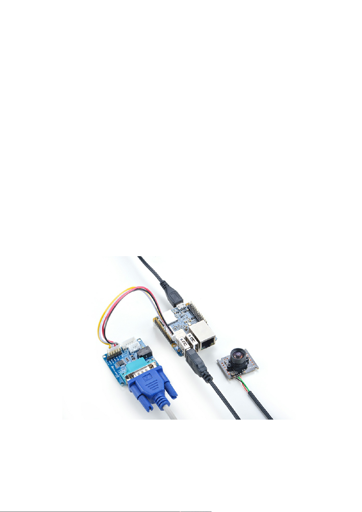
Connect NanoPi NEO Plus2 to USB Camera(FA-CAM202)
The FA-CAM202 is a 2M-pixel USB camera module. Boot your NEO Plus2, connect it to the internet, log in the
system as root, compile and run the mjpg-streamer utility:
10/13
Table of contents
Other FriendlyARM Motherboard manuals


