4
INSTALLATION REQUIREMENTS
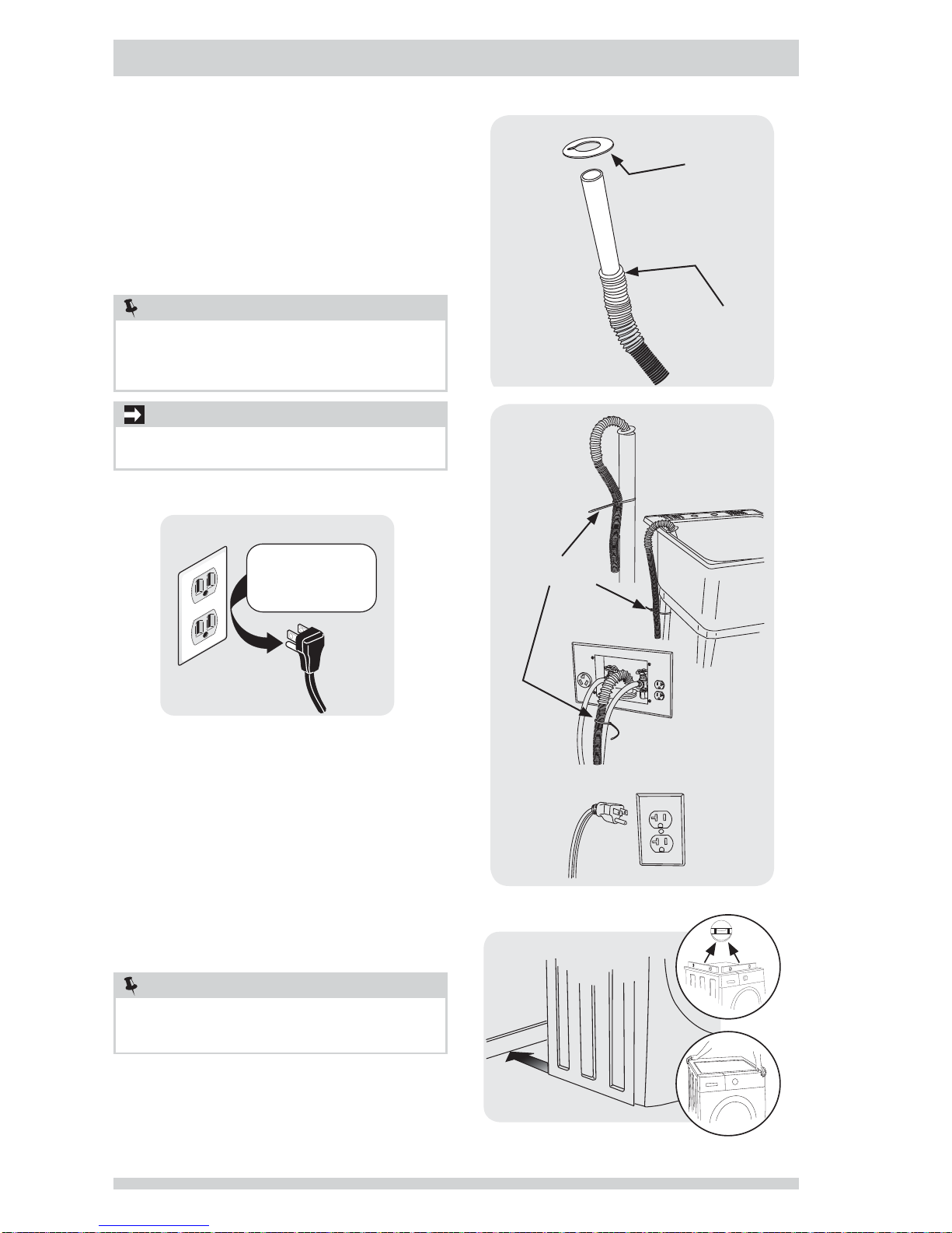
NOTE
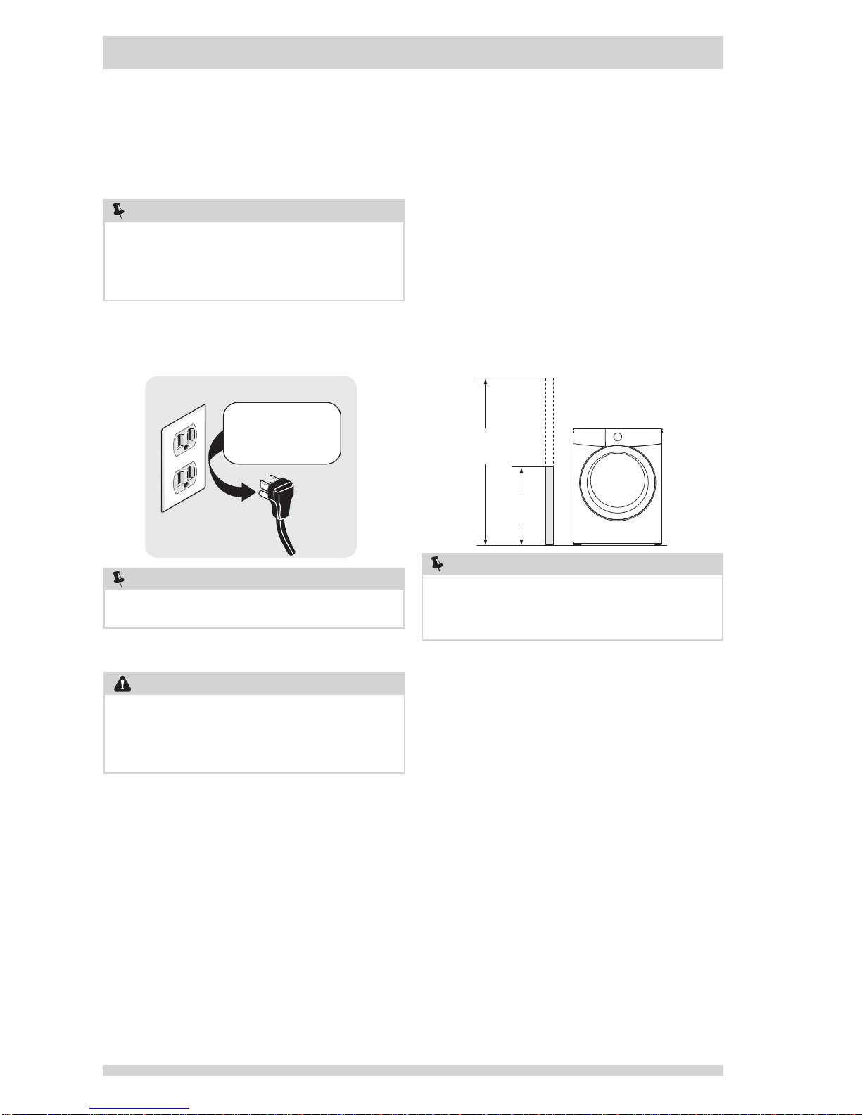
Drain hose attached to the washer can reach a 74 in.
(188 cm) high standpipe. For higher standpipe, use
hose P/N 137098000, available from an authorized
parts distributor.
NOTE
GFI (Ground Fault Interrupter) receptacle is not
required.
NOTE
Because of potentially inconsistent voltage capabilities,
the use of this washer with power created by gas
powered generators, solar powered generators, wind
powered generators or any other generator other than
the local utility company is not recommended.
CIRCUIT - Individual, properly polarized and grounded
15 amp. branch circuit fused with 15 amp. time delay
fuse or circuit breaker.
POWER SUPPLY - 2 wire, with ground, 120 volt single
phase, 60 Hz, Alternating Current.
OUTLET RECEPTACLE - Properly grounded 3-prong
receptacle to be located so the power supply cord is
accessible when the washer is in an installed position.
Grounding type
96”
(244cm)
max.
24”
(61cm)
min.
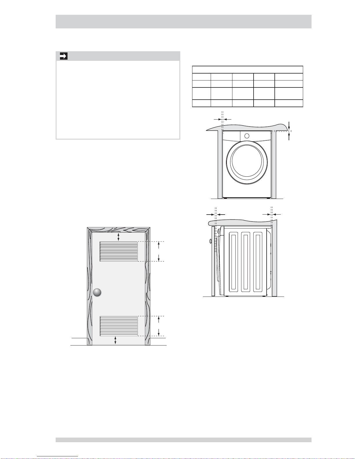
Drain system requirements
1Drain capable of eliminating 17 gals (64.3 L) per
minute.
2A standpipe diameter of 1-1/4 in. (3.18 cm)
minimum.
3The standpipe height above the floor should be:
Minimum height: 24 in. (61 cm)
Maximum height: 96 in. (244 cm)
Water supply requirements
Hot and cold water faucets MUST be installed within hose
length of your washer’s water inlet. The faucets MUST
be 3/4 inch (1.9 cm) with threading for laundry hose
connection. Water pressure MUST be between 30 and
120 psi. Pressure difference between hot and cold cannot
be more than 10 psi. Your water department can advise
you of your water pressure.
1The washer MUST be grounded. In the event of
malfunction or breakdown, grounding will reduce
the risk of electrical shock by a path of least
resistance for electrical current.
2Since your washer is equipped with a power supply
cord having an equipment-grounding conductor
and a grounding plug, the plug MUST be plugged
into an appropriate, copper wired receptacle that is
properly installed and grounded in accordance with
all local codes and ordinances or in the absence
of local codes, with the National Electrical Codes,
ANSI/NFPA 70 (latest edition). If in doubt, call a
licensed electrician. DO NOT cut off or alter the
grounding prong on the power supply cord. In
situations where a two-slot receptacle is present,
it is the owner’s responsibility to have a licensed
electrician replace it with a properly grounded three
prong grounding type receptacle.
Ground requirements
Electrical system requirements
WARNING
ELECTRICAL SHOCK HAZARD
Improper connection of the equipment grounding
conductor can result in a risk of electrical shock. Check
with a licensed electrician if you are in doubt as to
whether the appliance is properly grounded.