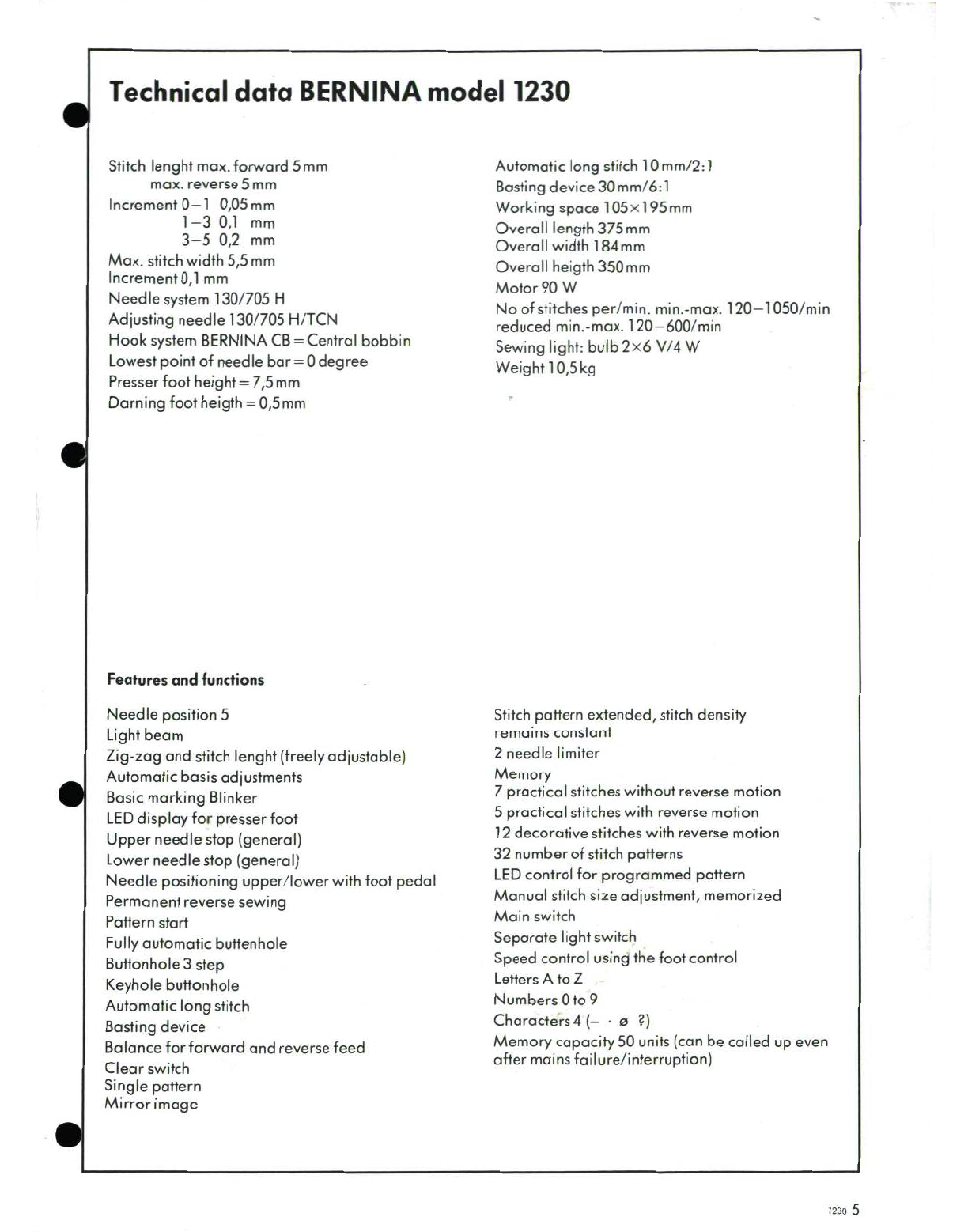
Fritz Gegauf BERNINA 1230 User manual

Contents
Page
Technical
data
5
Description
of
Print
L-4200
6
Print
A-1230
6
Print
S-1230
6
Block
schematic
model
1230
7
Plug
connections
8
Print
A-1230
9
Print
S-1230
10
Print
L-4200
11
Diagnosing
instructions
12
Test
adapter
L-4200
13
Power
supply
-
4200
14
Test
panel
-
1230
15
Test
programme
with
service-panel
16
Warning against
dangerous voltages
17
Starting
the
service
programme
17
Ending
the
service
programme
17
Diagnosis
18+19
Test
A
L-4200
20
B
Print
L-4200/R-4200
(Drive
signal)
21
C
Connection
S-1
230/L-4200
22
D
Mains
cord
(cord
reel)
23
E
Connection
of
print
S-1
230/foot
control
unit
24
F
Print P-4200
25
G
Complete
light
holder
26
Hi Step
motors:
27
o
PrintS-1230
o
Hall-sensors
H2
0
Position
Hall-sensorS.L.
28
o
Position
Hall-sensor
S.B.
I
Step
motors
pinning
position
29
K
Foot
control
unit
30
L
Foot
control
digital/analog
31
M
Print
A-1230
32
Print S-1230
Print
L-4200
N
Ret-button
33
0
Equalization
of
the
forward/reverse
feed
34
P1,2
Buttonhole
35+36
Q
Sewing-off:
37
o
Stitch
length
o
Stitch
width
o
Needle
position
L.C.R.
o
Long
stitch
Function
test
38
+
39
1230
3

Technical
data
BERNINA
model
1230
Stitch
lenght
max.
forward
5 mm
Automatic
long
stitch
10
mm/2:1
max.
reverse
5 mm
Basting
device
30mm/6:1
Increment
0-1
0,05mm
Working
space
105x195mm
1-3
0,1
mm
Overall
length
375mm
3-5
0,2
mm
Overallwidth
184mm
Max.
stitch
width
5,5
mm
Overall
heigth
350
mm
Increment
0,1
mm
Motor
90
W
Needle
system
130/705
H
No
of
stitches
per/min.
min.-max.
120-1050/min
Adjusting
needle
130/705
H/TCN
reduced
min.-max.
120-600/min
Hook
system
BERNINA
CB
=
Central
bobbin
Sewing
light:
bulb
2x6
V/4
W
Lowest
point
of
needle
bar =
0
degree Weight
10,5kg
Presser
foot
height
=
7,5
mm
Darning
foot
heigth
=
0,5
mm
Features
and
functions
Needle position
5
Stitch
pattern
extended,
stitch
density
Light
beam
remains constant
Zig-zag
and
stitch
lenght
(freely
adjustable)
2
needle limiter
Automatic
basis
adjustments
Memory
Basic
marking
Blinker
7
practical
stitches
without
reverse
motion
LED
display
for
presser
foot
5
practical
stitches
with
reverse
motion
Upper
needle
stop
(general)
12
decorative
stitches
with
reverse
motion
Lower
needle
stop
(general)
32
number
of
stitch
patterns
Needle
positioning
upper/lower
with
foot
pedal
LED
control
for
programmed
pattern
Permanent reverse
sewing
Manual
stitch
sizeadjustment, memorized
Pattern
start
Main
switch
Fully
automatic
buttenhole Separate
light
switch
Buttonhole
3
step
Speed
control
using
the
foot
control
Keyhole
buttonhole
Letters
A
to
Z
Automatic long
stitch
Numbers
0
to
9
Basting
device
Characters
4
(- -
o
?)
Balance
for
forward
and
reverse
feed Memory
capacity
50
units (canbe
called
up
even
Clear
switch
after
mains
failure/interruption)
Single
pattern
Mirror
image
1230
5
Downloaded from www.Manualslib.com manuals search engine

Description
The
electronics
of
the
model
1230
sewing
S-1230
control
print
machine
is
essentially located
on
three
large
The
complete sewing
machine
control
is
located
printed
circuit
boards;
the
power
print
L-4200,
the
on
the
S-1230
control
print.
The
S-1
230
control
control print
S-1230
and
the
display
print
A-1
230
print
is
located
on
the
A-1
230
printfrom
the
rear.
(compare
to
the
block
schematic
diagram).
The
The
most
important control
elements
are
the
tasks
of
the
3
units
correspond to
the
known microcomputer, and
the
power drive
for
the
step
functions
of
L-4200,
S-4200
and
A-4200 prints
motors.
A
new
feature
over
model
1130
is
that
the
from
the
model
1130.
bobbin
winder
motor
is
also
controlled
by
the
microprocessor.
The
bobbin winder
motor
speed
1-4200
powerprint
can
now
be
controlled
from
the
foot
control.
The
L-4200
power
print
is
mounted
above
the
The
S220
service
switch
on
print
S-1
230
isa
motor
on
the
rear
side
of
sewing
machine.
The
service
aid.
This
switch
has
two
positions:
normal
circuit
components
on
the
L-4200
have the
follow-
sewing
operation,
and
service
position.
In
the
ing
functions:
service
position,
several
buttons
and
diodes
on
-the
display
panel are
assigned
other functions.
-Motor
control:
This
allows
the
service
technician to
execute
The
main
motor
control
operates
with
the mains
necessary
adjustment
and
testing
functions
using
voltage.
The
main
motor
is
a
DC
motor
with
the
display
panel (refer to
the
special
section
pulse-width
modulated
speed
control.
The
service
programme).
The
service switch
must
closed
loop
control
circuit
on the
small
R-4200
always
be
set
into
the
sewing
position
for
normal
print
is
located
on
the
power
print.
sewing
operations.
All
circuit
components
for
the
motor
control
The
microcomputer
on
print
S-1
230
receives
an
operate
at dangerous
voltage
levels,
analog
signal
from
the
foot
control,
which it
then
The
safety
regulations
must
be
adhered to.
converts
into
a
digital
signal
and
transmits to
print
R-4200
as
setpoint
for
the
motor
speed.
The
-
Power supply:
R-4200
print
controls
the
motor
speed
to
the
Generates
the
following
D.C.
voltages:
speed
specified
by
the
S-print,
using
a
setpoint
-
-
30V
for
the
step
motors actual
value
comparison.
When
the
foot
control
is
-
5V
for
the
logic
circuitry
on
the
S-1
230
and
released,
the
setpoint
goes
to
zero,
the
brake
is
A-1230
prints
actuated
from
the
microcomputer
on
the
S-print
-
6V
for
the
sewing
light via
the
R-4200
print,
and
the
motor
is
rapidly
-
30V
for
the
bobbin winder
motor
braked.
Components
are
protected from
overload,
in
Signal
transfer
between
the
S-1230
and
R-4200
the
case
of
faults,
by
three
fuses
F
150,
F
151
print
is
realised
using
a
4-pole
cable.
Signal
and
F
152. If
a
fuse
blows
only
original
replace-
transfer
is
realised
through
an
opto-coupler
ment fuses,
with
the
correct
rating
may
be
used.
providing
electrical
isolation
and
thus
eliminating
dangerous
voltage
levels
from
the
foot
control
A-1230
display
print
and
the
S-1230
control print.
The
display
section
is
mounted
directly
behind
the
The
step
motors
are
in
random positions
when
operating
control
panel.
The
display
and
ope-
sewing
machine
is
switched
on.
Random
values
rating
control
elements
are
soldered
onto
the
L-
can
also
be
in
the
microcomputer control
shaped
printed
circuit.
memory.
In
order
to
have
a
defined
state,the
step
A
time
multiplex control
allows
the
numerous
motors
are
rotated
into
their
calibrated
position
LEDs
and
control
elements
to
be
connected
to
the
by
a
microcomputer
command, and
the
position
open
loop
control
on
the
S-1
230
control
print
value
is
set
to
zero
in
the
microcomputer
memory.
using
only
16
connection
lines.
This
starting
state
allows
the
selection
and
sewing
of
any
stitch
programme.
6
1230
Downloaded from www.Manualslib.com manuals search engine

Model
1230
block
schematic
L4200
F150
A
1230
A1230
RECTIFIER
J
FOOT
CONTROL
£
BUTTON
HOLE
SENSOR
S
REVERSE
SWITCH
D
-MAGNET
BASTING
DEVICE
0(
POSITION
INDICATOR
S4
WIDH
OBBINWINDER
ROTARY ENCODE
STITCH
WIGTHT
ROTAR ENCOE
ZUSERVICE
PROGRAMME
ROITAY
LENCOD
STITCH
WIDTH
STITCH
LENGTH
STEP
MOTORS
1230
7
Downloaded from www.Manualslib.com manuals search engine

0
I
Brake
P250
P
200
C
2
+!
5V
S
2
-2
S
E1"C4
3
Drive
green
2
2OX
4
Nominal
Vau
4re -L
2~ig~
S
gr
me1
Sewing
light
44
2o
CL
S.L.
5'
5
--
5
4
up
2
Step
motor
8
1
7__C_
4
S.B,
P
251
P2
+
5V
Mains
0
V
Hall-Sensor
1
3
S.L.
Housing
22
+5V
2
3
L
H
ll-Sensor
V,
M
ain
m
o r
4
4
n
osition
-S.B.
M
M
5 o + r
Magnet
7
6
-
asting
device
78
.8 t +'=
A- O1230
A13
S-1230t"o303K+1s 0
2
-0 CL
200
L-L20
5
SB
a13
St123
13
K-1130
1C4
3
red
+3
Bobwiwinder
0 30
R
4
ED
Rt
110
K-13
5 R-Button
• • • •
Downloaded from www.Manualslib.com manuals search engine

Print
A-1230
Utility
stitch
display
Needle
positions
Bar
graph
stitch
width
and
switches
Presser
foot
display
Buttonhole
display
Bar
graph
stitch
length
1230
9
Downloaded from www.Manualslib.com manuals search engine

S-1230
Print
Data
lines
to
print
A-1230
Potentiometer
for
adjusting
buttonhole
sensor
A
Potentiometer
for
adjusting
buttonhole
sensor
B
Foot
control
2-pole
black
Control
signals
from/to
L-print
4-pole
green
Buttonhole
sensors
Reverse
switch
6-pole
black
L-
Stitch
length
sensor,
3-pole
red
Stitch
width
sensor,
3-pole
black
Position
indicator
5-pole
black
Power
supply
from
L-print
5-pole
red
Magnet
basting
device,
2-pole
green
Service
switch
Pos.
Service
I
Pos.
Normal
Bobbin
winder
motor
4-pole
blue
Stitch
length
step
motor
4-pole
red
Stitch
width
step
motor
4-pole
black
Warning!
If
print
S-1230
has
to
be
replaced,
then
buttonhole
adjustment
and
forward/reverse
feed
equalization
must
be
carried
out.
10
1230
Downloaded from www.Manualslib.com manuals search engine

Print
L-4200
Important!
Never
fit
heat
sink
and
securing
screws
without
insulating
foil
or
insulating
washer,
because
a
short
circuit
will
occur.
The
heat
sink
with
its
Galvanically
insulating
foil
must
sit
fully
on
the
fixing
angle,
in
separated
order
to
achieve
best
results
in
transfering
heat
low
voltage
from
the
heat
sink
to
the
sewing
machine housing.
4-
Not
used
P157
P160
4 [
1
45V
41
I
Power
supply
for
P159
1-
print
S
and A-4200
1Control
signals
to
print S-4200
Sewing
light
Equalization
of
speed
Connector
for
print
R-4200
Main
motor
Circuits
in
this
area
operate
at
dangerous
voltages.
Observe
the
F
Main
notice
on
page
17.
Mains
123011
Downloaded from www.Manualslib.com manuals search engine

Diagnostic
instructions
-
As
opposed
to
model
1130,
model
1230
is
equipped
with
a
service
programme.
The
service
programme
is
essen-
tially
designed
for
test
and
adjustment
tasks.
-
The
diagnostic
instructions
should
be
adhered
to
for
repair
work.
Reference
should
be
made
to
the
service
programme
for
adjustment and
equalization
tasks.
Warning
of
dangerous
voltage
levels
Mains
voltage
(refer
to
print
L-4200)
Circuit
components
on
the
L-4200
power
print,
the
main
motor
and
the
cable
drum,
carry
dangerous
voltage
levels.
For
your
own safety,
print
L-4200
should
only
be
touched
after
about
30
seconds
after
the
mains
voltage
has
been
switched
off,
which
is
the
time
required
by
the
capacitors
to
discharge after
the
mains
plug
has
been
removed.
Warning:
The
sewing
machine
may
only
be connected
to
the
mains
supply
when the chassis
cover
or
the
auxiliary
cover
is
mounted.
Work
may
only
be
carried
out
on
the
L-4200
print,
main
motor
and
cable
drum
when the
mains
plug
has
been
withdrawn
from
the
mains
supply.
Electrically
isolated
low
voltages
(refer
to
print
L-4200)
Several
circuit
components
on
the
L-4200
print
operate
with
electrically
isolated
low
voltages
(40
V
or
less).
With
the
exception
of
the
power
print
L-4200,
the
main
motor
and
the
cable
drum,
the
other
modules
also
operate
with
elec-
trically
isolated low
voltages!
There
is
no
danger
involved
in
touching
these
components
during
operation.
Warning!
The
following
should
be
additionally
observed
when
carrying
out
repair
and
adjustment
work:
-
Changing
from
the
service
programme
to
normal
operation,
and
vice
versa
is
only
possible
after
changing
the
position
of
the
service
switch
on
the
S-1230
print,
and
briefly
switching
off
the
mains
voltage.
-
The
following
adjustments
should
be
made
each time
a
S-1230
print
is
replaced:
Forward/reverse
feed:
test
programme
0
Buttonholer:
test
programme
P
-
Switch
off
the
mains
voltage
before
touching
and
replacing
the
R-print.
12
1230
Downloaded from www.Manualslib.com manuals search engine

Test
adaptor
L-4200
The
power
supply
for
electrical
parts
which
are con-
nected
to
print
L-4200
and
the main
motor
control
are
checked
with
the
aid
of
the
test
adaptor.
"
When
all
LEDs
Ato
E
ligth
up,
then
the
power
supply
for:
-
the
step
motors
-
the
logic
circuit
-
the
sewing
light
is
correct.
Bobbin
winder
motor,
LED
E,
cannot
be
tested.
"
If
only
LED
B
doesn't
light
up,
then
the
voltage
for
the
logic
is
too
high (more
than 5,5
V).
*
If
only
LED
C
doesn't
light
up,
then
voltage
for
the
logic
is
too
low
(less
than
4,5
V).
*
When the
motor
switch
is
in
the
((on))
position,
the
electric
brake
is
released,
the
motor
receives
the
desired
value
and
will
run
at
the
set
speed.
LED
F
for
the
drive
signal
must
be
lit.
Speed
regulation
is
made
by
turning
the
potentiometer.
*
When the
motor
switch
is
placed
in
the
((off)
position
the
signal
returns
to
zero,
and
the
electric
brake
should
engage.
The
motor
slows
down
to
a
stop.
LED
F
must
go
out.
TEST
-ADAPTER
L
4200
r
30V
SCHRITTMOTOR
STEP
MOTOR
r-Bl
C,5v
0
5V
LOGIC
Ri>4,5V
0
F
6V
O
NAEHLICHT
~1
SEWING
LIGHT
E30V
0
SPULERMOTOR
BOBBIN
WINDER
BERNINA
=
LAUFSIGNAL
DRIVE
SIGNAL
TOFF@0ON
Q
MOTOR
1230
13
Downloaded from www.Manualslib.com manuals search engine

Power
supply
4200
The
power
supply
4200
delivers
current
for
the
logic
of
print
A-1
230
and
print
S-1
230,
the
step
motors,
the
sewing
light.
So
that
the
whole
machine
can
work
with
a
safe
low voltage,
the main
motor
receives
30 V
for
safety
reasons.
The
power
supply
is
useful
when
a
mechanical
adjust-
ment
is
to
be
made,
for
which
the
rigidity
plate
with
print
L-4200
has
to
be
removed.
Supply
apparatus
iI~1i4200
II~IIMotor
LW
IN
OFF
When
the
mains
switch
is
((on))
the
light
indicates
that
the
appliance
isworking.
With
the
switch
in
the
((off))
posi-
tion,
the
appliance is
turned
off.
Motor
switch
(ion)), the
main
motor
will
rotate
slowly.
Adaptor
print
with
cord
ist
pluggable.
There
is
a
400
mA
fuse
at
the
rear.
Important
cl.
1230:
The
connection
for
the
bobbin winder
motor
is
not
used.
14
1230
Downloaded from www.Manualslib.com manuals search engine

Test-Panel 1230
37
(5123456 =00 0o00M
SL
SB
HKALL~I
-
BLANCE
'3
..
SENSOR
-
POSITION
AUTO
84z
8+4+2+1
8 A
RET
5 Z
cn
0000.o0
000
~
HALL-
SENSOR
SL
SB
STOP
SL
SB
00j0
0*0-
1230
15
Downloaded from www.Manualslib.com manuals search engine

Test-Programmes
with
Service-Panel
Manual
What
is
to
be
tested
1230
See
also
service manual
1130
page
1
Hall
sensor
position
28
Page
64
a
(see
also
BERNINA
=
for
stitch
length
Information No.
78)
E
E2
Hall
sensor
position
28
cD
for
stitch
width
0
3
Sewing-off
(straight
stitch,
zigzag,
37
it
long
stitch
and
basting
stitch)
Cl)
0
o
Pinning
position
for
step
motors
29
Section
49, resp.
53
E
SL
and
SB
pages
37
+
41
E
0
Forward-reverse feed
34
Section
41,
pages
32
+
33
a
equalization
a-
Step
motor/Hall
27
Page
64
sensors
7
Position
indicator/
25
Page
62
P-print
8
Digital/analog
foot
control
31
9
Drive
signal
21
Page
58
10
Ret
button
33
11
Buttonholer potentiometer
35
Pages
69
+
70
equalization
16
1230
Downloaded from www.Manualslib.com manuals search engine

LDanger
high
level
voltage!
Mains
voltage
(see
print
L-4200)
Circuits
on
the
power
print
L-4200,
the
main
motor and
the
cord
drum
operate
at
dangerous
voltages.
As
some
capacitors
discharge
approx.
30
seconds
after
pulling
out
the
mains
plug,
you
should
wait
this long
before
touching
print
L-4200.
Test-programm
model
1230
(service
operation)
1.
Test-programme
start
-
Remove
belt
cover
(service
instructions model
1130,
section
6).
-
Set
service
switch
on the
S-print into
service
position (refer
to
Fig.
S-1
230,
page
10).
-
Switch-on sewing
machine/D.C.
mains
adaptor
unit.
The
sewing
machine
is
now
in
service
programme
no.
6
(step
motors), move
to
and
from
with
an
acustical
noise.
-
Push
clear
button
(min.
2
sec.).
-
Mount
service
panel.
The
sewing
machine
is
now
in
the
initial
state
of
the
service
operation.
The
individual
test
programmes
1
to
6
can
be selected
from
this
state.
The
initial
state
can
always
be
selected
by
depressing
the
clear
button.
The
following
sensor
signals
can
now
be
checked:
-
Position
indicator/P-print
(test
5
model
1130).
-
Foot
control
digital
and
analog
(new).
-
Drive signal
(partially
covered
in
test
1,
test
adaptor
model
1130).
-
Ret
button (new).
-
Adjust buttonholer
potentiometer
(partially
section
42
model
1130).
Termination
of
the
test-programme
-
Switch
off
the
sewing
machine/D.C.
mains
Attention:
adapter.
When
changeing
from
normal
operation
-
Service
-
Bring
the
service
switch
on the
S-print
into
the
operation
-
normal
operation.
normal
position.
-
Switch
off
the
machine/mains
adapter.
The
sewing machine
can
now
be
operated
-
Bring
the
serviceswitch
into
the
desired
position.
normally.
-
Switch
on
the
machine/mains
adapter.
1230
17
Downloaded from www.Manualslib.com manuals search engine

Fault
Possible
fault
on
Repair instructions
Display
panel
and
sewing
light
-
L-4200
print
-
Test
A, resp.
M
not
illuminated
-
Mains
cable
-
Test
D
Main
motor
not running
Machine
(dead))
Main
motor
does not
rotate other
-
L-4200
print
-
Test
A,
resp.
M
functions
OK
-
R-4200
print
-
Replace
R-4200
print
after
switching
off
mains
voltage
-
S-1230
print
-
Replace
S-1230
print
-
Foot
control
-
Check
control,
replace
bobbin winder
motor
foot
control,
if
nec.
test
K,L
-
Connection
between
S-1
230
and
-
Test
C
L-4200
prints
-
Connection
between
S-1
230
print
-
Test
E
and
foot
control
-
Main
motor
-
Check
motor
cable
and
plug
aReplace
motor
0
Bobbin
winder
motor
does not
function,
-
S-1230
print
-
Replace
print
S-1230
other
functions
OK
-
Bobbin
winder
-
Replace
complete
bobbin winder
Sewing
light
does not
function
-
Lamps
-
Replace
lamps
-
Lamp
holder
-
Test
G
-
Print
L-4200
-
Test
A
Step
motors
do
not
position
-
Step
motor
print
S-1230
-
Test
Hi,
H2
-
Connection
between
S-1230
and
L-4200 prints
-
Test
C
Front
panel
LED
does
not
illuminate,
Print
A-1
230
-
Replace
print
A-1230
however
selected
function
is
executed
when
button depressed
Downloaded from www.Manualslib.com manuals search engine

Fault
Possible
fault
on
Repair instructions
Selected
functions
not executed
when
-
Print
A-1230
-
Replace
print
A-i230,
if
malfunction
button
depressed
still
occurs,
replace
print
S-1230.
Test
with
new
S-1
230,
print
and
old
A-1
230
print.
Automatic buttonholing
does not
-
Buttonhole
foot
-
TestPlP2
function
-
PrintS-1230
-
Print
Ret-1230
Basting
device
does not
function
-
PrintS-1230
-
Replace
print
S-1230
-
Basting
device
magnet
-
Replace
magnet and
adjust
Reverse
button does
not
function
-
Print
S-1230
-
Start
service
test
programme,
depress
-
Print
Ret-1230
reverse
button,
LED
RET
must
illuminate,
if
not:
replace
print
S-1230
to Z
or
if
nec.
Ret
print.
Irregular
stitch
width
or
length
-
Step
motor
-
Test
Hi
H2
-
Check
mechnicol
and
optical
parts
of
Bar
graphs
do
not
react
to
stitch
-
Operating
chassis
the
rotary
encoder
adjustments
-
PrintA-1230
-
Replace
print
A-1
230
Main
motor
stops
after
5
seconds
-
Print
P-4200
-
Test
F
-
Print
S-1230
-
Replace
print
S-1230
No
needle
stop
-
Print
P-4200
-
Test
F
-
Print
S-1230
-
Replace
print
S-1230
-
Print
L-4200
-
Test
A
Stitch
pattern
no.
32
is
to
short
-
Feed
equalization
-
Test
0
=
orto
long
'0_ _ _ _ _ _ __ _ _ _ _ _ _ _ __ _ _ _ __O_ __ _ _ _ _ _ _ _
Downloaded from www.Manualslib.com manuals search engine

What
is
to
be
tested
What
to
adjust
Normal
condition
Print
L-4200
Switch
off
mains
supply
See
also directive
in
Test
M
-
Fit
safety
cover
-
Connect
test
adaptor
L-4200
instead
of
the
sewing
light
(2-pole,
green),
connect connecting
cable
to
print
S-4200
(4-pole
green,
control
signals)
and
connecting
cable to
print
S-4200
(5-pole
red,
supply).
-
Set
the
switch
on the
(off
position.
Switch
on
mains
supply
-
LEDsAto
D
illuminate
-
Motor
rotates.
LED
F
illuminated.
Speed
can
be
controlled
by
the
-
Motor
switch
to
oon)
position
potentiometer.
(see
also
test
B)
Motor
brakes.
LED
F
no
longer
-
Motor
switch to
aoffo
position
illuminated
Important:
-
When
no
lights
A-D
illuminate
carry
ont
test
D
mains
cord.
-
Replace
print
L-4200
if
one
or
several
of
the
LEDs
A
to
D
do
not
illuminate.
Before
going
further,
test
the
new
L-print
using
test
9
to determine
whether
the
L-print
failure
was
subsequent
to
failure
of
the
S-1
230
or
A-1
230
prints.
If
this
is
the
case,
then these
faults
should
first
be
eliminated.
-
Replace
print
R-4200
if
the
voltages
A-D
are
available
but
the
motor
still
does not
run.
Subsequently
replace
print
L-4200
if
the
motor
still
does not
run.
Downloaded from www.Manualslib.com manuals search engine

What
is
to
be
tested
What
to
adjust
Normal
condition
Print
L-4200/
R-4200
-
Initial
state
of
service
operation
(page
17)
-
Select
test
3
(sewing
trial)
-
The
LED
(signal)
is
Iluminated,
-
Depress
foot
control
the
motor
rotates.
-4
a
Repair
instructions:
-
If
the
LED
osignab)
M
is
not
illuminated:
A
test
should
be
conducted
with
a
new
R-print
and
the
old
L-print.
If
still
faulty,
then
replace
L-print and repeat
test.
If
still
faulty,
replace
S-print,
and
if
necessary
check
the
cable
connection
L-/S-print
(refer
to
test
C,
page
22).
Downloaded from www.Manualslib.com manuals search engine

What
is
to
be
tested
What
to
adjust
Normal
condition
Connection
of
print
S-1230
to
print
1230
-
Take out
mains
plug.
to
print
1230
a)
Disconnect connectors
from
print
Flat
cord
5
pol,
red
connectors
L-
and
S-4200
Flat
cord
4
pol,
green
connectors
b)
Check
on the
upper
side
of
the
connectors
with
a
circuit
tester
or
ohmmeter
that
each
wire
is
continuous.
c)
Test
every
wire
as
described
in
b).
/
• --
-
High pitched
tone!
Cord
ok.
-
Ohmmeter
shows
a
small
resitance,
cord
ok.
Important:
If
there
is
no
high pitched tone,
or
the
display
of
the
ohmmeter
wavers
or
shows
infinite
resistance,
then
the
cord
is
defective.
Replace
connection.
Downloaded from www.Manualslib.com manuals search engine
Table of contents
Other Fritz Gegauf Sewing Machine manuals