Friulinox Cube Series User manual

SERVICE MANUAL
REFRIGERATED CABINET
Cube and Hi-Cube Series

“go to TABLE OF CONTENTS”
FRIULINOX ALI GROUPS.R.L. A SOCIO UNICO 2
Via Treviso,4 - 33083 Taiedo di Chions (PN) -Italy
Service Manual
____________________________________________________________________________________________________________________________________________________________________________________________________________________________________________________________________________________________________________________________________________________________________________________________________________________________________________________________________________________________________________________________________________________________________________________________________________________________________________________________________________________________________________________________________________________________________________________________________________________________________________________________________________________________________________________________________________________________________________________________________________________________________________
The manufacturer reserves the right to modify the technical and functional features of the appliances described in this instruction manual without giving prior notice;
also, will not answer for any inaccuracies, attributable to printing or transcription errors, in this instruction manual.
The manufacture reserves the right to modify the technical and functional features of the appliances described in this instruction manual without giving prior notice; also,
will not answer for any inaccuracies, attributable to printing or transcription errors, in this instruction manual.
Il presente documento contiene Informazioni confidenziali e/o di proprietà di ALI GROUP S.R.L. A SOCIO UNICO. Non può essere usato, copiato e/o divulgato previo
consenso scritto di ALI GROUP S.R.L. A SOCIO UNICO. Se il seguente documento non è stato ricevuto direttamente da ALI GROUP S.R.L. A SOCIO UNICO, prego contattare
immediatamente l’Assistenza Post Vendita all’indirizzo e-mail [email protected] in modo tale da aiutare a prevenire possibili violazioni.
The present document contains confidential and/or proprietary information of ALI GROUP S.R.L. A SOCIO UNICO. It may not be used, copied and/or otherwise disclosed
without the prior written consent of ALI GROUP S.R.L. A SOCIO UNICO. If you have not received this document directly from ALI GROUP S.R.L. A SOCIO UNICO, please
contact the After Sales Department at e-mail address servic[email protected] immediately to help prevent possible violations.

“go to TABLE OF CONTENTS”
3FRIULINOX ALI GROUPS.R.L. A SOCIO UNICO
Via Treviso,4 - 33083 Taiedo di Chions (PN) -Italy
Service Manual
TABLE OF CONTENTS
1. General Warnings ................................................................................................................................................................... 5
1.1. Positioning and reading the data plate ....................................................................................................................... 6
2. Company History .................................................................................................................................................................... 7
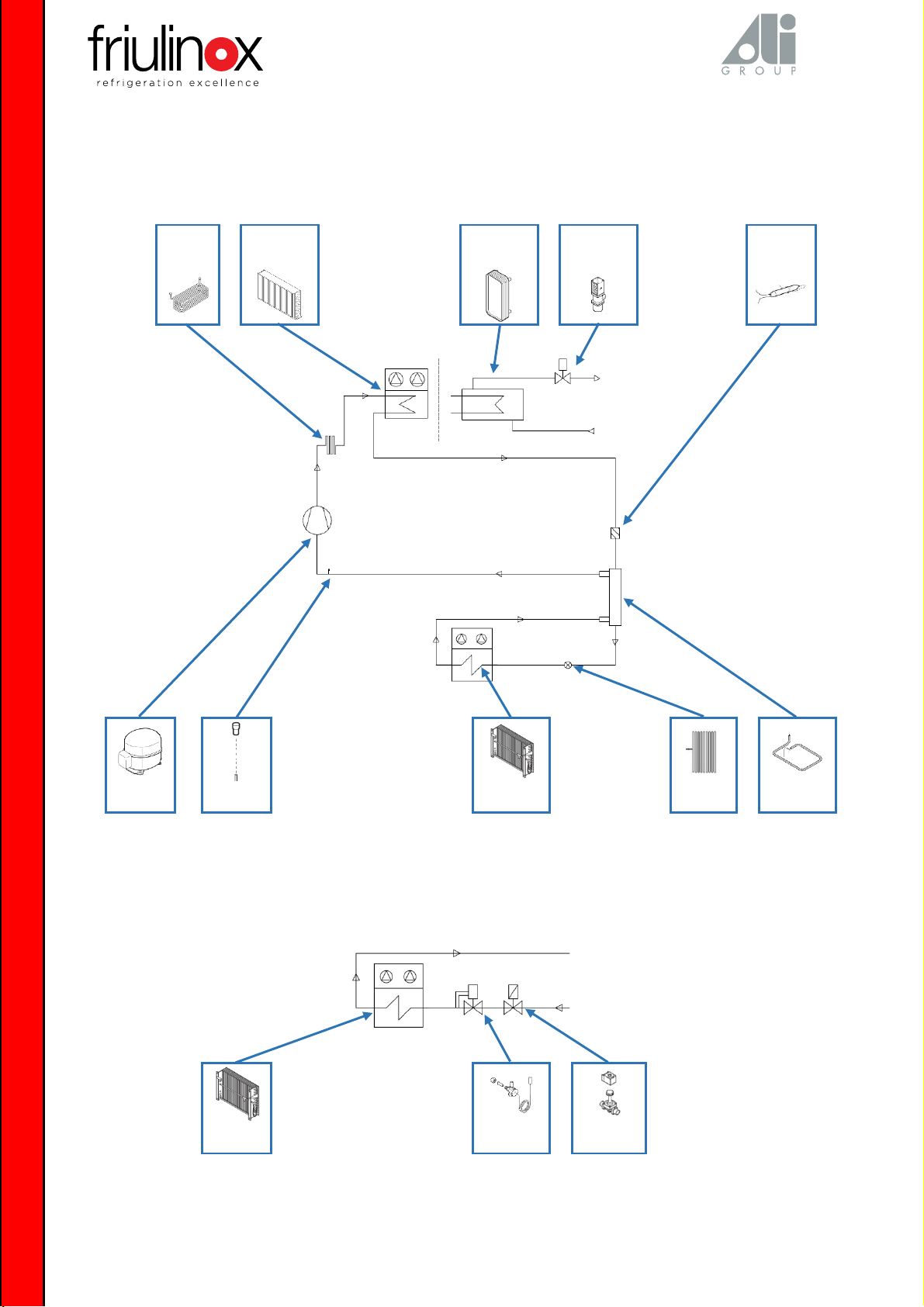
3. Explanation of the refrigeration system................................................................................................................................... 8
3.1. Unit on board............................................................................................................................................................ 8
3.2. Set-up for remote unit ............................................................................................................................................... 8
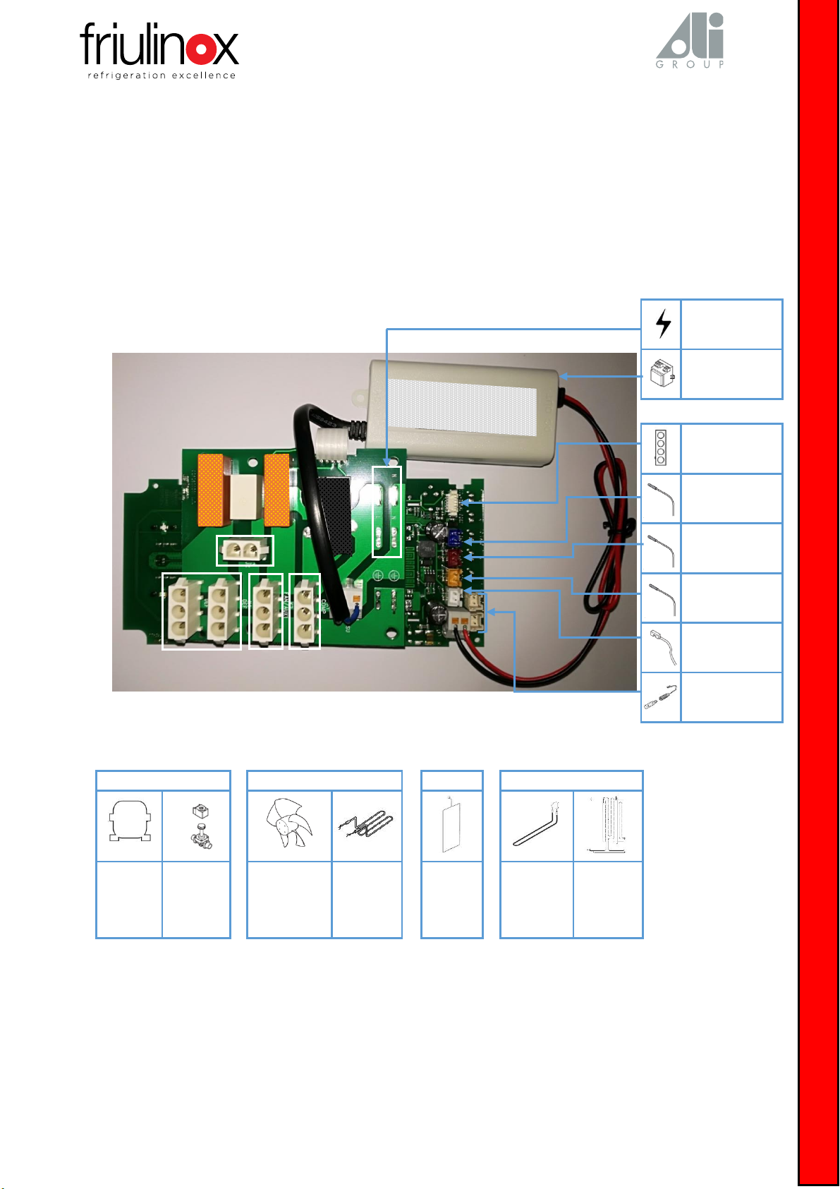
4. Explanation of the electronic board......................................................................................................................................... 9
4.1. 700lt Haccp Basic cabinet board................................................................................................................................. 9
4.2. 700-1400lt Haccp Basic cabinet board...................................................................................................................... 10
4.3. 700-1400lt Haccp cabinet board + “rtc” clock module............................................................................................... 11
4.4. Specific electronic board connections ...................................................................................................................... 12
4.5. Temperature probes tables...................................................................................................................................... 15
5. Installation checklist ............................................................................................................................................................. 16
6. Routine maintenance............................................................................................................................................................ 18
7. Electronic board operation.................................................................................................................................................... 20
7.1. Board functions ....................................................................................................................................................... 20
7.2. Access to the service menu...................................................................................................................................... 21
7.2.1. Parameter access .................................................................................................................................... 21
7.2.2. Access to internal values.......................................................................................................................... 24
7.2.3. Access to alarms...................................................................................................................................... 24
7.2.4. Reset data memories (HACCP) ................................................................................................................. 26
7.2.5. Reset factory values ................................................................................................................................ 26
7.2.6. HACCP..................................................................................................................................................... 26
8. Interventions on the equipment............................................................................................................................................ 27
8.1. Electronic board replacement .................................................................................................................................. 27
8.2. Door opening inversion...........................................................................................Errore. Il segnalibro non è definito.
8.3. Door gasket replacement......................................................................................................................................... 33
8.4. Frame heater replacement ...................................................................................................................................... 34
8.5. Condenser filter panel removal and cleaning............................................................................................................ 36
8.6. Monoblock unit components replacement ............................................................................................................... 37
8.6.1. evaporator fan ........................................................................................................................................ 37
8.6.2. defrosting heater..................................................................................................................................... 39
8.6.3. KLIXSON thermostat ................................................................................................................................ 42
8.6.4. drain heater ............................................................................................................................................ 45
8.6.5. air probe ................................................................................................................................................. 48
8.6.6. evaporator probe .................................................................................................................................... 51
8.6.7. condenser probe ..................................................................................................................................... 53
8.6.8. compressor ............................................................................................................................................. 55
8.6.9. condenser fan ......................................................................................................................................... 56
8.7. Door microswitch replacement ................................................................................................................................ 57
8.8. Lock replacement .................................................................................................................................................... 58
8.9. Cell light replacement.............................................................................................................................................. 59

“go to TABLE OF CONTENTS”
FRIULINOX ALI GROUPS.R.L. A SOCIO UNICO 4
Via Treviso,4 - 33083 Taiedo di Chions (PN) -Italy
Service Manual
TABLE OF CONTENTS
9. Diagnostics ........................................................................................................................................................................... 61
9.1. Board alarms........................................................................................................................................................... 61
9.1.1. Probe 1 Faulty: air probealarm................................................................................................................. 61
9.1.2. Probe 2 Faulty: evaporator probe alarm................................................................................................... 62
9.1.3. Probe 3 Faulty: condenser probe alarm.................................................................................................... 63
9.1.4. Overheat.Cond.: overheated condenser alarm ......................................................................................... 64
9.1.5. Comp. Locked: locked compressor alarm ................................................................................................. 65
9.1.6. Rtc error: clock module alarm.................................................................................................................. 66
9.1.7. Minimum Temp.: low temperature in cell alarm....................................................................................... 67
9.1.8. Maximum Temp.: high temperature in cell alarm ..................................................................................... 68
9.1.9. Door open: door open alarm.................................................................................................................... 69
9.1.10. Power Failure: power supply interruption alarm....................................................................................... 70
9.1.11. Defrost.Timeout: defrosting concluded by duration.................................................................................. 71
9.2. Malfunctions not managed by board........................................................................................................................ 72
9.2.1. The display board does not switch on ...................................................................................................... 72
9.2.2. The display board is on but the relay outputs are not managed ................................................................ 73
9.2.3. The display board is on but it is not possible to access the functions by pressing the keys ......................... 74
9.2.4. The compressor does not work during the cooling phase.......................................................................... 75
9.2.5. The system works but the equipment does not cool................................................................................. 76
9.2.6. Ice formation on evaporator.................................................................................................................... 78
9.2.7. Formation of ice on evaporator casing, air intake and exhaust duct .......................................................... 80
9.2.8. Condensation formed on the cabinet frame lids....................................................................................... 82
9.2.9. Water overflow from condensate drain tray............................................................................................. 83
9.2.10. The evaporator fan does not work ........................................................................................................... 84
10. Wiring diagrams.................................................................................................................................................................... 85
11. Service contacts.................................................................................................................................................................... 87

“go to TABLE OF CONTENTS”
5FRIULINOX ALI GROUPS.R.L. A SOCIO UNICO
Via Treviso,4 - 33083 Taiedo di Chions (PN) -Italy
Service Manual
1. GENERAL WARNINGS
ATTENTION! Live equipment. Always disconnect voltage when performing
maintenance and cleaning on the equipment.
ATTENTION! Potentially dangerous situation that could harm people or
damage objects near-by.
SUGGESTION
Ideas or advice for maintenance or intervention.
ATTENTION:
THE USE OF NON-ORIGINAL SPARE PARTS PURCHASED FROM THIRD PARTIES NOT
AUTHORISED BY FRIULINOX ALI GROUP SRL, AND THEIR MODIFICATION IN A
CONFIGURATION DIFFERENT FROM THE ORIGINAL, CANCEL THE EQUIPMENT AND
COMPONENT WARRANTY. FRIULINOX ALI GROUP SRL AND ITS AUTHORISED CENTRES
WILL NOT BE HELD LIABLE FOR COMPLAINTS, DAMAGES AND COSTS CAUSED DIRECTLY
OR INDIRECTLY BY CHANGES NOT APPROVED AND VALIDATED BY THE SAME.
DO NOT CLEAN THE EQUIPMENT WITH PRESSURE WATER.
DO NOT WORK ON THE EQUIPMENT WITHOUT HAVING READ THIS MANUAL.
DO NOT WORK ON THE EQUIPMENT IF THE ACCESS PANELS ARE NOT CORRECTLY
POSITIONED AND SECURED.
DO NOT WORK ON THE EQUIPMENT IF NOT CORRECTLY INSTALLED AND SERVICED.
PAY ATTENTION WHEN MOVING THE EQUIPMENT. IT CAN WEIGH FROM 50 KG TO 257
KG. USE THE SPECIFIC LIFTING SYSTEMS
CONNECTION TO THE POWER MAINS AND THE CONNECTION SYSTEMS MUST MEET THE
REGULATIONS IN FORCE IN THE COUNTRY OF INSTALLATION OF THE EQUIPMENT AND
MUST BE CARRIED OUT BY QUALIFIED PERSONNEL AND AUTHORISED BY THE
MANUFACTURER.

“go to TABLE OF CONTENTS”
7FRIULINOX ALI GROUPS.R.L. A SOCIO UNICO
Via Treviso,4 - 33083 Taiedo di Chions (PN) -Italy
Service Manual
2. COMPANY HISTORY
1972
1987
2003
2004
2016
FRIULINOX is established in Azzano Decimo (PN) as
company specialised in the production and sale of
professional refrigeration.
It becomes part of the ALI GROUP, one of the most
important world market leaders of systems and equipments
dedicated to the catering market. The same year it
inaugurate the new, more modern and productive Villotta
plant, thus expanding its market offer
The first Multifunctional equipment is conceived, which paves
the way to a new way of managing the kitchen, becoming the
crucial tool of production processes.
FRUILINOX markets the fist blast chilling systems,
starting their distribution together with training
sessions, accompanying users towards a new way of
conceiving and managing production processes
With the acquisition by the METOS Group, it has the
possibility to supply the technology to a wider
audience.

“go to TABLE OF CONTENTS”
FRIULINOX ALI GROUPS.R.L. A SOCIO UNICO 8
Via Treviso,4 - 33083 Taiedo di Chions (PN) -Italy
Service Manual
3. EXPLANATION OF THE REFRIGERATION SYSTEM
3.1. Unit on board
Condensate
evaporatio
n coil
Air condenser
Water
condenser
Pressure valve
Dehydrator
filter
Compressor
Pressure
socket
Ventilated
evaporator
Capillary
Exchanger pipe
3.2. Set-up for remote unit
Ventilated
evaporator
Thermostatic
valve
Solenoid valve
of the liquid

“go to TABLE OF CONTENTS”
9FRIULINOX ALI GROUPS.R.L. A SOCIO UNICO
Via Treviso,4 - 33083 Taiedo di Chions (PN) -Italy
Service Manual
4. EXPLANATION OF THE ELECTRONIC BOARD
4.1. 700 litre HACCP BASIC cabinet board code BN1681210
Temperature range:
0 ÷ +10°C / -2 ÷ +8°C / -25 ÷ -15°C / -22 ÷ -18°C / -20 ÷ -15°C / -6 ÷ +4°C
Power supply
(230V)
Transformer
(T1)
Serial port
NTC probe thermostat
NTC probe defrosting
NTC probe condenser
Microswitch
(ID1)
Glass doors/cell light
(E1)
K1
K2
K3
K4
Compressor
control
(M1)
Liquid
solenoid valve
(Q2)
Fan
evaporator
(M3)
Condensate
evaporation
trayl heater
(E3- optional
for remote
unit)
Frame
heater
(E4)
Defrosting
heater (E2)
Condensate
drain heater
(E8)
K1
K4
K3
K2

“go to TABLE OF CONTENTS”
FRIULINOX ALI GROUPS.R.L. A SOCIO UNICO 10
Via Treviso,4 - 33083 Taiedo di Chions (PN) -Italy
Service Manual
4.2. 700/1400 litre HACCP BASIC cabinet board code BN1681212
Temperature range:
0 ÷ +10°C / -2 ÷ +8°C / -25 ÷ -15°C / -22 ÷ -18°C / -20 ÷ -15°C / -6 ÷ +4°C
Power supply
(230V)
Transformer
(T1)
Serial port
NTC probe thermostat
NTC probe defrosting
NTC probe condenser
Microswitch
(ID1)
Glass doors/cell light
(E1)
K1
K2
K3
K4
Compressor
control
(M1)
Liquid solenoid
valve (Q2)
Fan
evaporator
(M3)
Condensate
evaporation tray
heater
(E3)
Glass anti-
condensation
heater
(E7)
Frame heater
(E4)
Defrosting
heater (E2)
Condensate
drain heater
(E8)
K1
K2
K3
K4

“go to TABLE OF CONTENTS”
11 FRIULINOX ALI GROUPS.R.L. A SOCIO UNICO
Via Treviso,4 - 33083 Taiedo di Chions (PN) -Italy
Service Manual
4.3. Cabinet board 700/1400 litre HACCP-”rtc” CLOCK MODULE code BN1681232
Temperature range:
0 ÷ +10°C / -2 ÷ +8°C / -25 ÷ -15°C / -22 ÷ -18°C / -20 ÷ -15°C / -6 ÷ +4°C
Power supply
(230V)
Transformer
(T1)
NTC probe thermostat
Serial port
DC fans
(evaporator fans
12 VDC - optional)
Glass doors/cell light
(E1)
Microswitch
(ID1)
NTC probe condenser
NTC probe defrosting
K1
K2
K3
K4
Compressor
control
(M1)
Liquid solenoid
valve (Q2)
Fan
evaporator
(M3)
Condensate
evaporation tray
heater
(E3)
Glass holder
anti-
condensation
heater
(E7)
Frame heater
(E4)
Defrosting
heater (E2)
Condensate
drain heater
(E8)
K1
K2
K3
K4

“go to TABLE OF CONTENTS”
FRIULINOX ALI GROUPS.R.L. A SOCIO UNICO 12
Via Treviso,4 - 33083 Taiedo di Chions (PN) -Italy
Service Manual
4.4. Specific electronic board connections
M1
Compressor
The operation of the M1 compressor and of the “Q2” liquid solenoid valve is
managed by the “K1” relay.
The solenoid valve is installed - on request - on all models set-up for the
remote unit.
Compressor ON delay from first switch-on parameter C0.
Compressor minimum time OFF-ON parameter C1.
Compressor minimum time OFF parameter C2.
Compressor minimum time ON parameter C3.
∆T OFF of the parameter r0 compressor.
Compressor OFF time with faulty air probe(Probe 1 Faulty) parameter C4.
Compressor ON time with faulty air probe(Probe 1 Faulty) parameter C5.
The “M2” condenser fan is connected in parallel to the compressor.
Q2
Solenoid valve
of the
liquid
M3
Evaporator fan
The M3, E3 and E7 operation is managed by the K2 relay.
The E3 heater, connected in parallel to the M3 evaporator fan, is installed on
all models set-up for the remote unit.
The E7 heater, connected in parallel to the M3 evaporator fan, is installed on
the models with glass door.
Fan (M3) management during normal operation, parameter F0, (default 8 =
fan works according to the humidity set, set on display).
Fan OFF with upper evaporator temperature at parameter F1.
Fan management during defrosting and dripping, parameter F2 (0 = fan OFF;
1 = fan ON).
Fan maximum OFF time, parameter F3.
F1 parameter differential, parameter F8.
E3
Condensate
evaporation tray
heater
E7
Glass anti-
condensation
heater
E4
Frames heater
The E4 operation is managed by the K3 relay, parameter u1, default set 4.
The E4 heater is installed on all TN –BT –TNV –BTV models.
Cell temperature above which the frames heater is at OFF, parameter u5.
Operation time during maximum Energy Saving level, parameter r16.
Operation time during average Energy Saving level, parameter r17.
E1
Glass door light/cell
light
It activates when the door is opened, parameter i0=5.
The light can be manually activated from the menu light on.
NTC probe
thermostat
Air temperature
probe
NTC type probe temperature range -40°C to +105°C.
Positioned in the evaporator intake duct.
A fault of the probe or of the analogue input of the board determines the
Probe 1 Faulty alarm.
Probe calibration parameter CA1.
Type of probe, parameter P0 (1=NTC).
The decimal point of the temperature is managed with parameter P1.
°C or °F setting parameter P2.
Minimum work setpoint, parameter r1.
Maximum work setpoint, parameter r2.
Enable work setpoint change lock, parameter r3=1.

“go to TABLE OF CONTENTS”
13 FRIULINOX ALI GROUPS.R.L. A SOCIO UNICO
Via Treviso,4 - 33083 Taiedo di Chions (PN) -Italy
Service Manual
NTC probe
defrosting
Evaporator probe
NTC type probe temperature range -40°C to +105°C.
It is positioned on the evaporator.
A fault of the probe or of the analogue input of the board determines the
Probe 2 Faulty alarm.
Probe calibration parameter CA2.
Type of probe, parameter P0 (1=NTC).
The decimal point of the temperature is managed with parameter P1.
°C or °F setting parameter P2.
Evaporator probe function, parameter P3.
Minimum evaporator temperature during overcooling, parameter r6.
NTC probe
condenser
Condenser probe
NTC type probe temperature range -40°C to +105°C.
Not available on the models set-up for the remote unit.
It is positioned on the condenser outlet tube.
A fault of the probe or of the analogue input of the board determines the
Probe 3 Faulty alarm.
Probe calibration parameter CA3.
Type of probe, parameter P0 (1=NTC).
The decimal point of the temperature is managed with parameter P1.
°C or °F setting parameter P2.
Condenser probe enabled by parameter P4 (1=environment/condenser
probe).
Condenser temperature above which the OVERHEAT.COND. alarm is
activated, parameter C6.
Condenser temperature above which the “Comp. Locked” locked compressor
alarm is activated, parameter C7.
I3
Door microswitch
Detects whether the door is closed or open during the equipment operation.
Its intervention determines the Door Open alarm.
The effect caused by the door microswitch is managed by parameter i0.
Door microswitch polarity parameter i1.
Door open alarm signal delay, parameter i2.
HACCP menu Door open alarm memorisation enable, parameter i4.
Activates defrosting with door opening duration longer than parameter i14.
E2
Defrosting heater
The operation of the E2 and E8 heaters is managed by the K4 relay.
The models with temperature range 0-10°C have defrosting for compressor
stop, parameter d1 =2.
The E2 heater is equipped with KLIXSON thermostats (B2), connected in
series, that intervene when the working temperature > 70 °C.
The E8 heaters are connected together and managed as a single piece.
Interval between defrosts, parameter d0.
Type of defrost, parameter d1 (0=electrical; 1=hot gas 2=stop –models with
range 0-10°C).
Defrost end temperature, parameter d2.
Defrost duration, parameter d3.
Temperature display during defrost, parameter d6.
Dripping duration, parameter d7.
Defrost type, parameter d8: 0 at intervals; 3 adaptive; 4 in real time (only for
models equipped with “rtc” clock module).
Defrost activation in real time, parameters Hd1,2,3,4,5,6, with d8=4 (only for
versions with “rtc” clock module).
E8
Condensate drain
heater

“go to TABLE OF CONTENTS”
FRIULINOX ALI GROUPS.R.L. A SOCIO UNICO 14
Via Treviso,4 - 33083 Taiedo di Chions (PN) -Italy
Service Manual
T1
Transformer
The start-up and operation of the electronic board are guaranteed by the
12VDC power supply generated by the transformer.
The 12VDC power supply is also used to power the cell LED lights and glass
doors (optional).
230V
Power supply
Power supply voltage 230V with +/- 10% tolerance.
The power part of the board (K1/K2/K3/K4 relay) is powered directly at 230V.
Serial Port
Serial Port
Allows to connect the equipment for data download.
B11
Pressure switch
High pressure safety pressure switch installed on the water condensed
models. It intervenes at 29.5BAR and resets at 24.5BAR.
ATTENTION: the intervention of the safety pressure switch cuts-off the
main power supply of the equipment.

“go to TABLE OF CONTENTS”
FRIULINOX ALI GROUPS.R.L. A SOCIO UNICO 16
Via Treviso,4 - 33083 Taiedo di Chions (PN) -Italy
Service Manual
5. INSTALLATION CHECK LIST
Refrigerated cabinets installation checklistrev0 of 17/11/2017
Customer name
Installation date
Address
Installer technician
City
Installer company
Country
Model
Tel. no.
Serial number
E-mail address
Power supply voltage
Reference contact
Checks
Notes
Check the package status and integrity
Check for aesthetic defects
Remove the protective film from all surfaces
Cabinet installed on wheels?
YES □
NO □
Condensing unit on the machine?
YES □
NO □
Check that the evaporator cover is correctly
fastened with belt
Indicate the available space around the storage cabinet:
left side - minimum 50 (mm)
…………..
right side - minimum 50 (mm)
…………..
front (mm)
…………..
back - minimum 50 (mm)
…………..
above - minimum 500 (mm)
…………..
Indicate the equipment around the cabinet (oven/refrigerator/blast chiller/refrigerated
counters/worktable/dishwasher/wall/free/other)
left side
…………………………………………………………………………………………………………………….
right side
…………………………………………………………………………………………………………………….
front
…………………………………………………………………………………………………………………….
back
…………………………………………………………………………………………………………………….
above
…………………………………………………………………………………………………………………….
Level equipment (recommended inclination of 2%
to the front)
Electrical connection
Make sure that the power socket is equipped
with a 30mA thermal breaker
Connect the single-phase models to the power
socket via Shuko plug (already installed)
Only for water-condensation units (WL)
Check the seal of the hydraulic connections
Indicate the condenser inlet water pressure - max
5 (bar)
…………..
Indicate the condenser inlet water temperature -
max 30(°C)
…………..
Calibrate the pressure valve at 13 - 15 bar (WL
version only)

“go to TABLE OF CONTENTS”
17 FRIULINOX ALI GROUPS.R.L. A SOCIO UNICO
Via Treviso,4 - 33083 Taiedo di Chions (PN) -Italy
Service Manual
Functional testing
Detect room temperature for cooling test with
cabinet empty
…………..
Detect cabinet temperature before starting the
cooling cycle
…………..
Set temperature of -2°C to test the positive
cabinet or temperature of
-20°C for the negative cabinet
-2°C □
-20°C □
Indicate time (min) to reach -2°C or -20°C in the
cabinet (within max 60’)
…………..
Check door gasket seall
Check defrost cycle operation
Set and indicate the storage temperature
required by the Customer (°C)
…………..
Illustrate the basic functions of the equipment
Deliver user manuals, certificates, test reports to
the customer
Final test date
Name of technician
Customer name
Customer signature/stamp for acceptance

“go to TABLE OF CONTENTS”
FRIULINOX ALI GROUPS.R.L. A SOCIO UNICO 18
Via Treviso,4 - 33083 Taiedo di Chions (PN) -Italy
Service Manual
6. ROUTINE MAINTENANCE
Refrigerated cabinets scheduled maintenance rev0 of 17/11/2017
Customer name
Installation date
Address
Installer technician
City
Installer company
Country
Model
Tel. no.
Serial number
E-mail address
Power supply voltage
Reference contact
Frequency
Checks
Notes
Every
month
Every
12m.
Every
24m.
Clean the air condenser and the filter (Customer)
Clean the door gasket with water-based neutral
detergent (Customer)
Clean the inside and outside of the cabinet with
water-based neutral detergent (Customer)
Clean the electrical box
Clean the condensate evaporation tray
Make sure the door closes properly, otherwise
adjust the hinge
Check the condition of the frame lids
Check all electrical connections on the terminal
board
Check the integrity of the power supply cable
Check the condition of all refrigerator components
Check for gas leaks on the system
Verification of electrical absorption
Evaporator fans (A)
…………..
Frames heater (A)
…………..
Defrosting heater (A)
…………..
Condensate drain heater (A)
…………..
Compressor (A)
…………..
Condenser fan (A)
…………..
Component replacement
Replace condenser filter
Replace the door gasket
Frame lids replacement
Replace lamp (if not working)

“go to TABLE OF CONTENTS”
19 FRIULINOX ALI GROUPS.R.L. A SOCIO UNICO
Via Treviso,4 - 33083 Taiedo di Chions (PN) -Italy
Service Manual
Functional checks
Check air probe reading at the temperatures of +2°C
and -20°C
-2°C □
-20°C □
Detect room temperature for cooling test with
cabinet empty
…………..
Detect cabinet temperature before starting the
cooling cycle
…………..
Set temperature of -2°C to test the positive cabinet
(TNN) or temperature of
-20°C for the negative cabinet (BT)
-2°C □
-20°C □
Indicate time (min) to reach -2°C or -20°C in the
cabinet (within max 60’)
…………..
Set and indicate the storage temperature required
by the Customer (°C)
…………..
Date of maintenance
Name of technician
Customer name
Customer signature/stamp for acceptance

“go to TABLE OF CONTENTS”
FRIULINOX ALI GROUPS.R.L. A SOCIO UNICO 20
Via Treviso,4 - 33083 Taiedo di Chions (PN) -Italy
Service Manual
7. ELECTRONIC BOARD OPERATION
7.1. Board functions
equipment ON/OFF.
KEY UP Menu item scrolling and value increase. If no programme selected, it increases setpoint values.
KEY DOWN Menu item scrolling and value decrease. If no programme selected, it decreases setpoint values.
MENU/ENTER Main menu of controls or set value confirmation.
ESC Exit from menu or interruption without saving data.
ENERGY SAVING Access to energy saving menu.
COMPRESSOR If flashing, compressor protection in progress.
DEFROST If flashing, compressor protection in progress or
dripping in progress.
EVAPORATOR FAN If flashing, fan stop in progress.
CELL LIGHT ON If flashing, light automatically on.
DOOR OPEN
ALARM OR ERROR IN PROGRESS
Operating range
Cabinet temperature
Selected mode
Temperature setpoint/Humidity
setpoint
Energy Saving Bar
OPERATING STATUS ICONS
Operation status
This manual suits for next models
1
Table of contents