IV
The fuel is supplied in the form of gaseous hydrogen. Hydrogen is a dange-
rous substance, which requires great care when handling. Further informati-
on on handling hydrogen can be found in the EU RL 91/155 EEC and 93/
112 EU safety data sheets.
Only use the device in well ventilated areas to prevent the accumulation of
explosive gas. Spaces are not deemed to be at risk of explosion if a concen-
tration of hydrogen of less than 4 % can be guaranteed by the use of natural
or forced ventilation.
Connect suitable hydrogen ventilation lines to the screw connections provi-
ded as described in the „Commissioning“ section and run them into the
open air to dissipate the excess hydrogen in the event of overpressure in
the hydrogen supply.
The unit should be set up so that it is independent of the surrounding air.
This means that the reaction and cooling air is supplied from the atmosphe-
re and the outgoing air from the reaction chamber and cooling system is
dissipated into the atmosphere.
If such a setup is not possible, operating the device to use ambient air is
only permitted:
- if protective grilles are fitted to the housing openings for the inlet and
outlet cooling air (factory setting)
- if there is sufficient ventilation
- in rooms with a volume of more than 130 m³
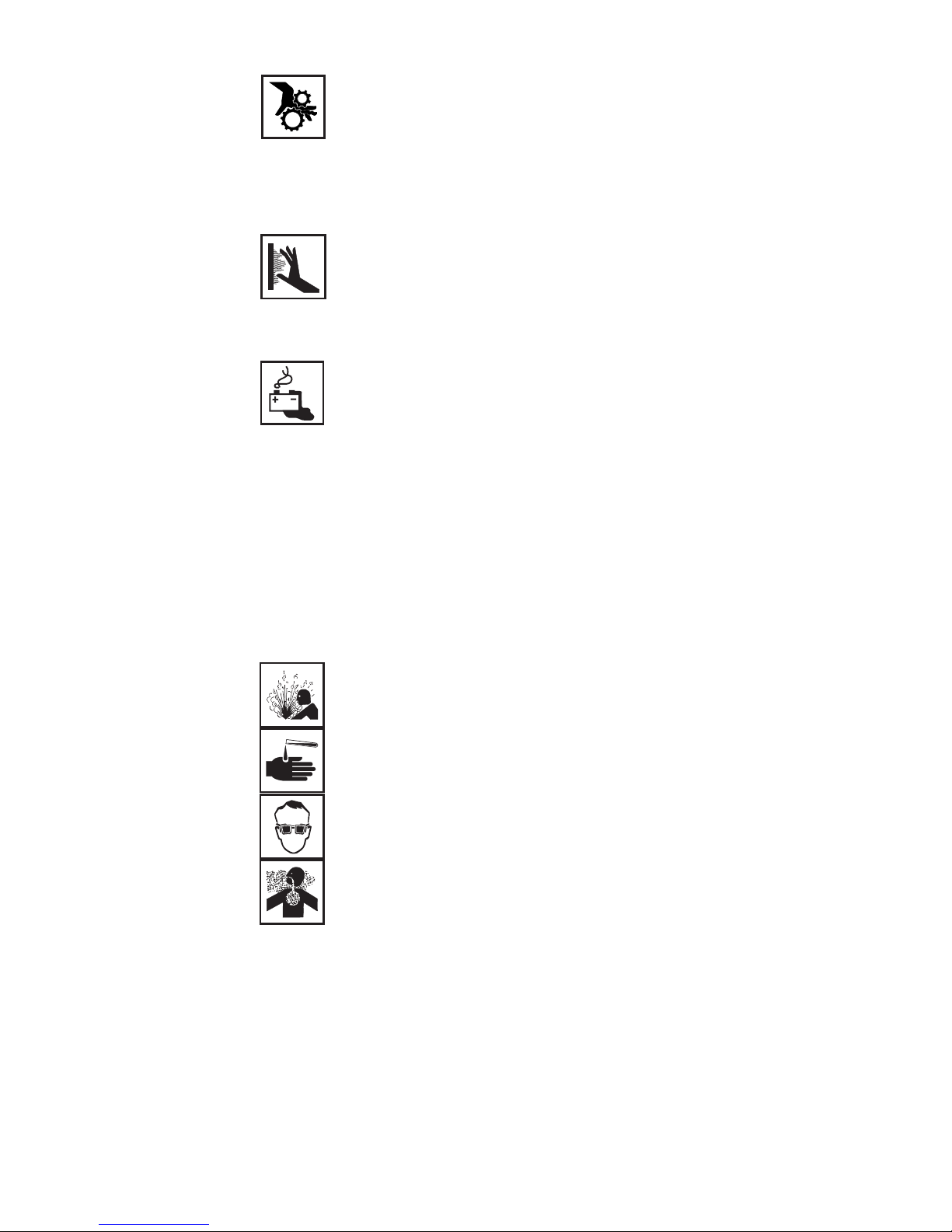
Danger from
gases, hazardous
materials and
suffocation
Keep all people, especially children, away from the unit and its accessories.
If, however, there are people in the vicinity,
- make them aware of all the dangers associated with the back-up battery
(risk of a build-up of explosive acids and gasses that are detrimental to
the health, possible risk of suffocation due to lack of oxygen in the air,
danger from output current, etc.)
- provide suitable protective equipment.
Before leaving the work area, ensure that no-one and nothing can come to
any harm in your absence.
Protecting
yourself and
others
CAUTION! Danger of suffocation when the unit is operated in
areas with inadequate ventilation (uses up the oxygen). Ensure
an adequate supply of fresh air.
Using the device in spaces with inadequate ventilation can cause suffocati-
on with no visible or otherwise detectable warning. The cause of this is the
oxygen consumption of the device, which can lead to a lack of oxygen in the
room if it is inadequately ventilated. Setting up the device to take in and
expel air into the atmosphere rather than the room helps prevent this. For
more information on this, see the chapter entitled „Commissioning“.