3
DEUTSCH
3
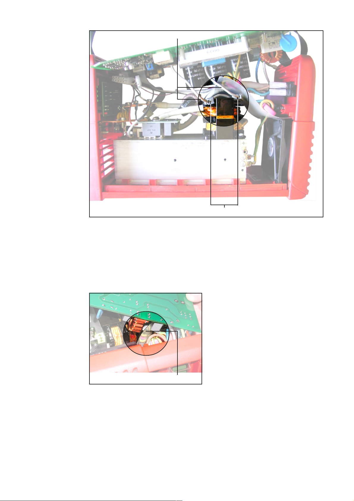
Hinweis! Beim Abnehmen des Prints
LCA15 (1) darauf achten, daß keine Kabel
eingeklemmt, geknickt oder auf Zug
belastet werden.
- Print LCA15 (1) vorsichtig vom Kühlkör-
per abnehmen
Hinweis! Beim Abklemmen der Trafolei-
tungen (44) für den Print LCA15, WAGO-
Klemmen (45) vollständig zusammendrük-
ken.
- „Trafoleitungen Print LCA15“ (44)
abklemmen
(45)
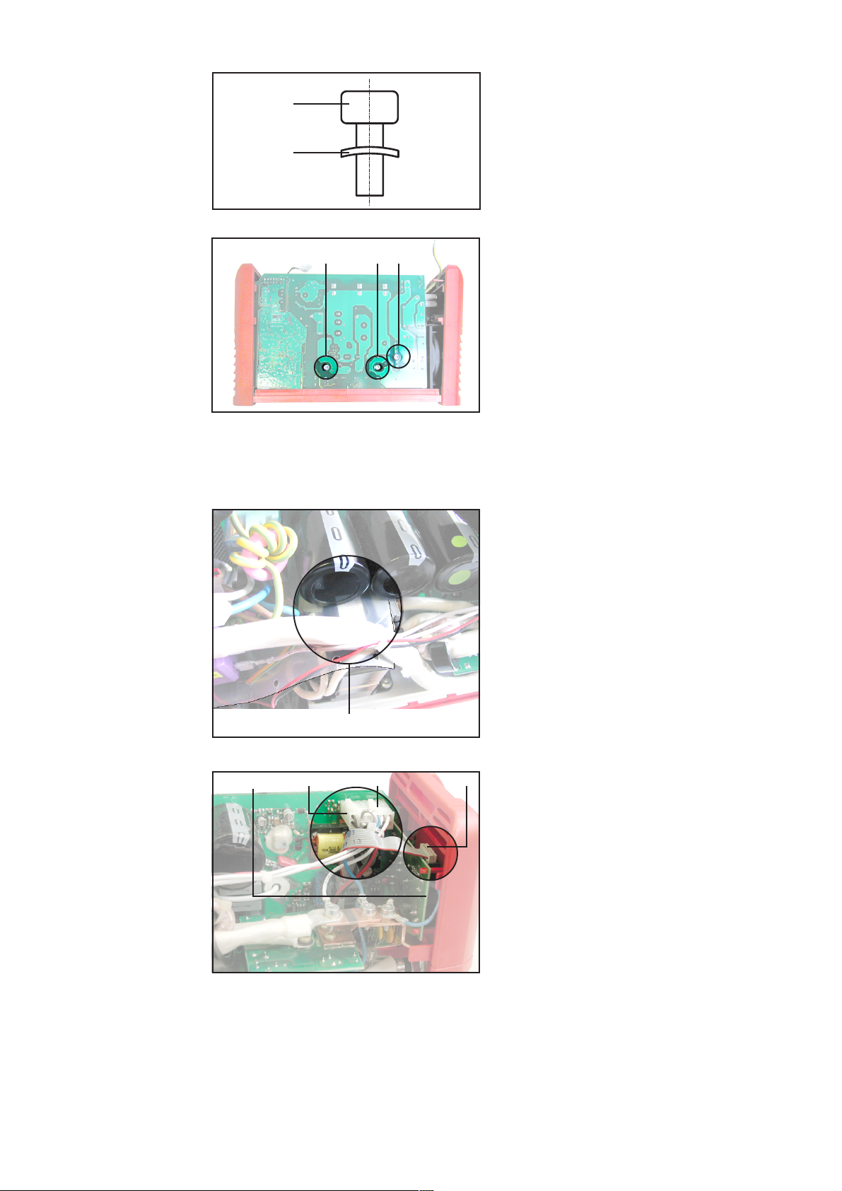
- Kühlkörper mit Kontaktspray und nicht
faserndem Tuch vorreinigen
- Am Kühlkörper Verunreinigungen bzw.
Unebenheiten mit feinem Schleifpapier
(Körnung P 500 oder feiner) beseitigen
- Kühlkörper mit Kontaktspray und nicht
faserndem Tuch reinigen
- Schutzfolie (46) vom Transistormodul
(47) abziehen
LCA15 einbauen
(46)
(47)
Hinweis! Vor der Montage des Prints
LCA15 den festen Sitz des Erdungsbol-
zens M4x17 (48) - Schlüsselweite 7 -
prüfen. Gegebenfalls mit 2 m nachzie-
hen.
(48)
(44) (1)
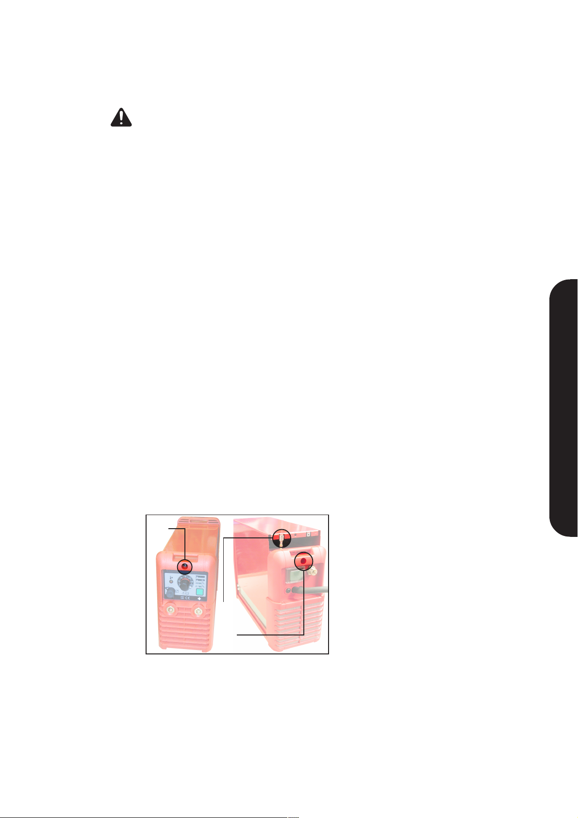
Hinweis! Beim Anklemmen der „Trafolei-
tungen Print LCA 15“ (44), WAGO-
Klemmen (45) vollständig zusammendrük-
ken. Auf eine korrekte Polarität braucht
nicht geachtet zu werden.
- Trafoleitungen für den Print LCA15 bis
zum Anschlag in die WAGO-Klemmen
(45) einführen (Pfeile) und auf festen
Sitz prüfen
(45)
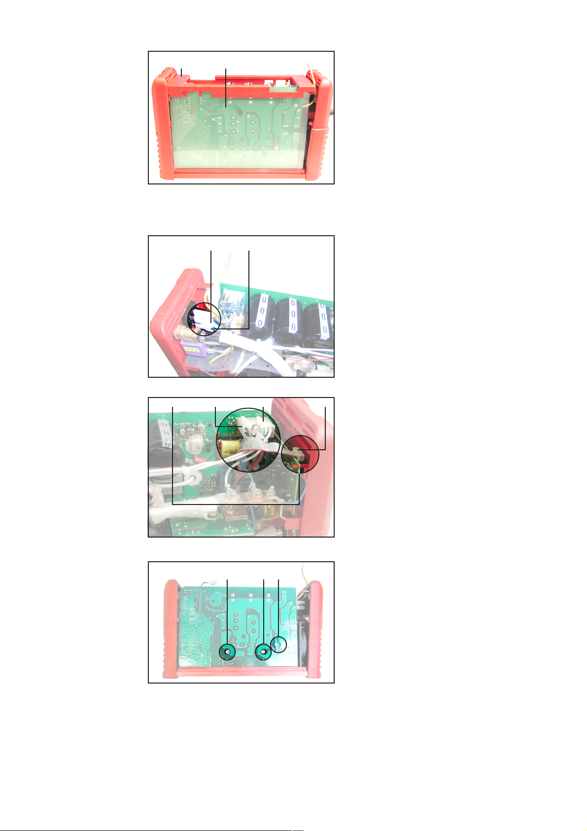
Abb.6
Abb.7
Abb.8
Abb.9
Abb.10
(48)
(44)
LCA15 ausbauen
(Fortsetzung)