Froilabo TRUST Series User manual

User manual
Ref: UM_TRUST/EN_rev1.0
ULT FREEZER
TRUST -45°C / -86°C

Please read carefully this manual before first use!
This document has been prepared with the utmost care possible. However,
Froilabo declines all responsibility in the event of errors or omissions. The
same applies to any damage arising from the use of information contained in
this manual.

Table of contents
1.
Certificate of conformity ............................................................................................................................................ 2
2.
Warranty.................................................................................................................................................................... 2
3.
General informations ................................................................................................................................................. 3
4.
First contact with your freezer ................................................................................................................................... 3
4.1 Delivery and unpacking........................................................................................................................................... 3
4.2 Implantation and installation.................................................................................................................................... 4
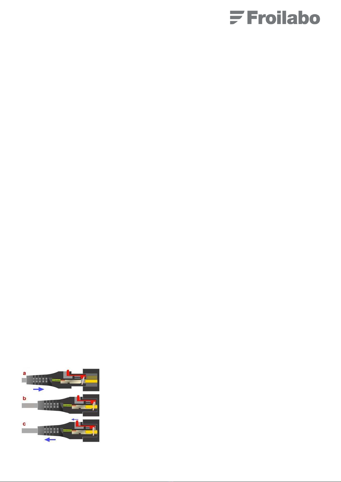
4.3 Power supply........................................................................................................................................................... 4
4.4 Temperature range .................................................................................................................................................5
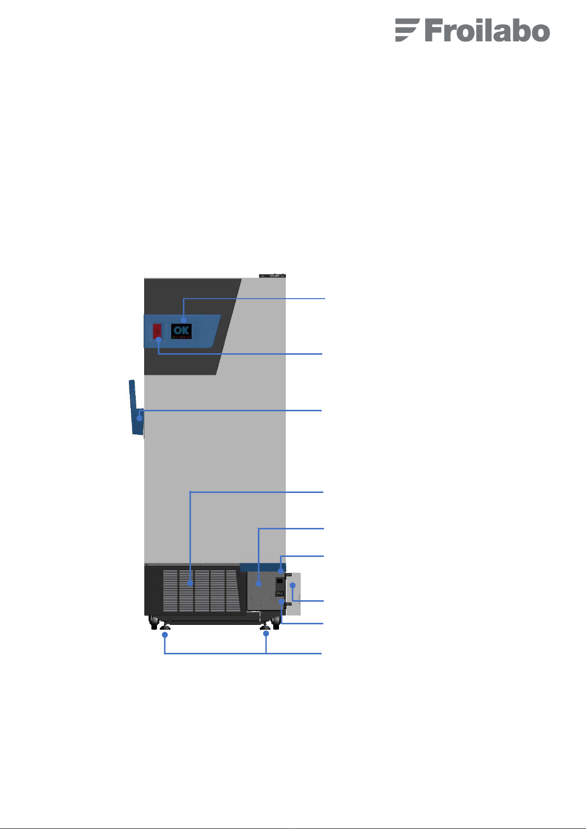
4.5 Construction and isolation....................................................................................................................................... 5
4.6 Technical characteristics and refrigeration system .................................................................................................7
4.7 Sample storage ....................................................................................................................................................... 8
4.8 Control panel........................................................................................................................................................... 8
4.9 Starting up............................................................................................................................................................... 9
5.
Using PXF4 regulator..............................................................................................................................................10
5.1 Ajusting setpoint temperature ............................................................................................................................... 10
5.2 Setting high and low temperature alarms ............................................................................................................. 10
5.3 Setting CO
2
/ LN
2
injection ....................................................................................................................................11
6.
Indicators et alarms LED.........................................................................................................................................11
6.1 Main power connected ..........................................................................................................................................11
6.2 Temperature alarm (high or low)...........................................................................................................................11
6.3 Overpressure CP1 ................................................................................................................................................12
6.4 Battery charge failure ............................................................................................................................................12
6.5 Open door alarm ...................................................................................................................................................12
6.6 Engine failure ........................................................................................................................................................12
6.7 CO
2
/LN
2
injection in progress ...............................................................................................................................12
7.
Maintenance and customer services.......................................................................................................................13
7.1 Security rules ........................................................................................................................................................13
7.2 Mainteance, cleaning and decontamination..........................................................................................................13
7.3 Long time stop....................................................................................................................................................... 14
7.4 Problems encountered and solutions....................................................................................................................15
8.
Security ...................................................................................................................................................................16
8.1 Liquid CO
2
backup ................................................................................................................................................ 16
8.2 LN
2
backup............................................................................................................................................................17
9.
Transportation et waste disposal ............................................................................................................................ 19
9.1 Transportation .......................................................................................................................................................19
9.2 Waste disposal...................................................................................................................................................... 19
10.
Customer services...............................................................................................................................................19
SERVICE CONTRACT ...................................................................................................................................................20

1
WARNING: GENERAL INFORMATION AND SAFETY INSTRUCTIONS
It is strictly necessary to follow the instructions for use of this manual to ensure the proper functioning of the device or
to exercise a possible recourse warranty.
Using this manual :
•
Read these instructions carefully before using the device for the first time.
•
Follow the instructions in the operating instructions.
•
This manual is part of the product. Please conserve it.
•
If you need to transfer this unit, do not forget to contact the operating instructions.
•
In case of loss, upon request, we will provide you with a new user manual.
Concerning these devices, some risks are to be taken into consideration (indicated by symbols):
ENVIRONNEMENT:
This device may contain fluorinated greenhouse gases under the KYOTO protocol.
Waste treatment methods: Do not allow the product to disperse into the environment.
Destruction / Disposal: Consult the manufacturer or supplier for information on recovery or recycling.
Companies installing, servicing, maintaining, repairing or commissioning equipment containing refrigerants must have
a certificate referred to in Article R543-76 of the French Environment Code or an equivalent certificate issued in one of
the member states of the European Union.
This pictogram is intended to draw your attention to informations, observations of great importance,
potential danger or a risk of personal injury.
Information:
this symbol informs the user of advice and additional information allowing him / her to make
optimal use of the product.
Warning!
This symbol indicates the safety measures to be followed by the user or the technician, in
order to guarantee the physical integrity of people in the vicinity of the device. These measures must be
followed with the utmost care.
The pictogram is intended to remind you to pay attention to hot surfaces.
The pictogram is intended to remind you to pay attention to electric risk.
The pictogram is intended to remind you to pay attention to risk of asphyxiation.
Danger extreme cold temperature ! Potential hazard due to ultra-low temperature of the freezer and
contents.

2
1. Certificate of conformity
FROILABO SAS hereby certifies that the equipment listed below:
Low temperature freezers -45°C and Ultra Low Temperature freezers -86°C TRUST (TRU)
Comply with the applicable standards and technical directives:
•EN 61010-1 – Safety requirements for electrical equipment for measurement, control and laboratory use - Part
1: general requirements,
•2014/35/EU – Low Voltage Directive,
•2014/30/EU – EMC Directive, Class A equipment.
Nota: this equipment is not designed for operation in explosive atmospheres (ATEX). Furthermore, they may not be
used to store flammable, corrosive or explosive substances.
2. Warranty
Optimal performance will be achieved following correct installation and operating instructions provided in that manual.
Froilabo SAS guarantees that the equipment will operate optimally in accordance with the conditions of installation and
use set out in this manual.
The warranty period is: 24 months.
This warranty is extended to:
•5 years on the following parts: fan, compressors, condenser and regulator*
•10 years on the VIP insulation
During this period, in case of malfunction of your device, the warranty is limited to:
•free repair or exchange of equipment
•functioning improvement
It must be clear, however, that the trouble or failure must be related to a defect in the material or workmanship. Any
other claim for compensation is excluded.
Lifespan of the product is 10 years minimum.
Intended use includes following the instructions in the user manual and performing the inspection and maintenance
work.
The photos used in this document are not contractual.

3
3. General informations
Ensure that all persons installing, using and repairing the equipment are aware of the potential hazards
related to their work, to respect the safety measures and have read and understood the instructions included
in this user manual.
If hazardous or potentially hazardous substances are used, only persons fully familiar with the equipment should handle
these substances. These persons must be capable to conduct an overall assessment of the potential risks. Please
contact us if you have any questions regarding the use of the equipment or the instructions. Under no circumstances
may Froilabo be held liable for the quality of material stored in the freezers.
Nota: the equipment that you have purchased is designed for professional use. Nevertheless, impacts to the frame and
vibrations should be avoided. Ensure that the equipment is inspected at regular intervals appropriate for the frequency
of use. Also check (at least once every two years) that labels relating to safety and unauthorised use are properly in
place. If backup systems using liquid CO
2
or N
2
vapour injection are used, please refer to the corresponding safety data
sheets.
4. First contact with your freezer
4.1 Delivery and unpacking
Use a pallet truck to move the freezer on its pallet. It is imperative to keep the freezer unpacked to avoid any risk of
tipping over. The device can be placed on the ground and maneuvered thanks to the wheels. After positioning the device
in the desired location, remove the various protective plastics and shims.
Do not forget to remove the foam padding shelves (at the bottom thereof) to avoid damaging the gates when closing
the door once the freezer is at -80 ° C.
Froilabo freezers are delivered on a pallet equipped with an unloading ramp. In fact, they do not require specific
equipment to get off the pallet. Please refer to the handling and unpacking sheet attached to the device.
After the reception, please check the contents of the delivery.
Do not use sharp objects to avoid damaging the paint. Do not tip the device. Preserve the device as much
as possible from all vibrations. Two people are needed to move the device.
Protective gloves should always be worn!
340 liters 515 liters 690 liters
1 detachable power cord L=2.50m with IEC19 connector
1 filter cassette
1 set of 2 keys
1 pressure relief valve + 1 x foam valves + 1 x spare foam valves
1 user manual
1 shelf 2 shelves 3 shelves
2 brackets
4 brackets 6 brackets

4
4.2 Implantation and installation
The freezer is designed for use under the following environmental conditions (according to EN 61010-1):
•Indoor use only
•Maximum altitude: 2000 m
•Ambient temperature range of 18 ° C to 32 ° C
•Maximum relative humidity of 80% for temperatures up to 22 ° C
•Supply voltage ripple < ±10 % of rated voltage
•Supply network voltage surges: category II (Standard IEC 60364-4-44)
•Maximum level of room contamination: 2
TRUST freezers are Class A devices within the meaning of the EMC Directive.
In order to minimize energy consumption and granted annonced performances, place the unit in a well-ventilated room,
away from sources of heat (radiator, heating ...) and avoid direct exposure to the sun. Place it on a flat surface. It is
essential for its proper functioning that the device is level. If necessary, use rigid shims.
It is important to ensure that no obstacle (wall, switchgear) interferes with the ventilation of the appliance (air inlet and
outlet). Remove about 200mm from each side of the freezer.
Lower the 2 front levelling feet, by performing an additional ¼ turn after contact with the ground.
The temperature of the room must not exceed + 35 ° C. The moisture content in the air should ideally not exceed 50%
RH. The use of air conditioning can significantly extend the life of compressors.
If you are using a liquid CO
2
or LN
2
liquid backup device, refer to the safety data sheets at the end of this manual.
4.3 Power supply
See the manufacturer's plate on the back of the device, 3 models exist:
-Tension 230V ~ +/-10%, 50 Hz, protection par fusible "aM 12 A"
-Tension 110V ~ +/-10%, 50/60Hz, protection par fusible "aM 20 A"
-Tension 220V ~ +/-10%, 60Hz, protection par fusible "aM 12 A"
For the voltage 220V ~ +/- 10% 60 Hz, refer to the characteristics of the voltage 230V ~ +/- 10% 50 Hz of the table in §
4.6.
The power supply must be single-phase, in accordance with the manufacturer's plate on the rear of the unit. It must be
equipped with a safety device ensuring the automatic shutdown of the power supply in the event of an insulation fault,
such as a properly sized differential circuit breaker.
In order to allow the electrical disconnection of the appliance, the circuit breaker must be immediately identifiable and
within easy reach of the operator
Your freezer is equipped with a detachable IEC connector with blocking.
The insertion of the male connector into the female connector (step a) is carried out
normally.
To remove the IEC connector (step c), slide the red pull tab back to allow the male
connector to be removed from the female connector.

5
4.4 Temperature range
The TRUST freezer is factory preset to optimized power consumption.
On the-86°C model, the setting ranges from -55°C to - 90°C, default setting being -80°C.
On the -45°C model, the setting ranges from -20°C to -45°C, default setting being-45°C.
The ambient temperature (recommanded between +18°C and +32°C, ideally between 20°C and 25°C) has a major
influence on the power consumption of the equipment.
4.5 Construction and isolation
The one-piece electro-galvanized steel exterior body is protected by an epoxy paint.
The inner tub is made of stainless steel. The thermal insulation is ensured by a set of insulating panels under vacuum
/ polyurethane foam. The insulated swing door is mounted on a pivot.
The closing and sealing of the door is ensured by a progressive tightening handle.
Screen with LED alarm indicator
Alarm window with silencer
Lock equipped handle
Filter cassette
Lower door with plexiglass windows
Levelling feet
24V switch
Disk recorder (optionnal)
Regulator
Front view

6
Heated pressure relief valve
The pressure relief valve allows a balance of pressures between the inside and the outside of the freezer which makes
it easier to open the door.
Frequent doors opening promotes the introdution of moisture in the freezer and may induce frost formation after the air
intake tube to which the valve is attached. A calibrated foam is placed into the air intake tube to limit this phenomenon.
Froilabo freezers are equipped with a heated pressure relief valve allowing a quick return to the ambient pressure
inside the enclosure, either after a door opening or after the injection of CO
2
or LN
2
, and that without ice formation in
the valve well.
In normal operation, this vlave does not require any maintenance.
The heating element of the valve starts to heat when the temperature inside the freezer reaches -15 ° C.
However, check regularly (depending on use) that the pressure relief valve (located on the side of the device) and the
calibrated foam are working properly. Reposition properly after cleaning.
After stopping the freezer completely, remove the valve foam to dry. Before restarting the freezer, replace the dry foam.
After CO2 or LN2 injection, it is necessary to dismantle the decompression valve and reposition the inner circular silicone
membrane properly in order to ensure the correct sealing inside of the valve.
Heating door seal :
Froilabo freezers are equipped with a heating door seal to prevent the formation of ice and thus maintain an optimal
seal of the freezer.
Refer to the "Maintenance, cleaning and decontamination" section for cleaning the door seal.
Air filter :
In order to maintain the cooling performance of the device and to preserve the compressors lifespan, an air filter is
placed in front of the condenser.
It is necessary to dust or wash this filter as frequently as necessary.
A device must never operate without a filter.
Clamping handle :
The device has a progressive tightening handle. Its double-action makes it easier to open and close the door. The
freezer door can be locked thanks to the key lock located on the side of tha handle.

7
4.6 Technical characteristics and refrigeration system
Technical characteristics:
Characteristics TRUST Freezers
340L 515L 690L
-86°C -45°C -86°C -45°C -86°C -45°C
General
Raw volume (liters) 340 340 515 515 690 690
Number of compartments 2 2 3 3 4 4
Freezer weight (kg) 223 178 267 222 330 285
Power consumption* at 230 V at 50 Hz (Watts) 900 1000 1150 1000 1150 1000
Power consumption* at 110 V at 60 Hz (Watts) 1000 1100 1400 1100 1400 1100
Minimum cooling capacity of the rooom containing
the continuous freezer (Watts)
850 950 1200 950 1200 950
Sound pressure measured in dB(A) (in regulation
mode)
56
External dimensions
Height (mm) 1280 1280 1640 1640 2000 2000
Width (mm) 875 875 875 875 875 875
Depth (mm) 970 970 970 970 970 970
Required clerance at the back of the device (mm) 200 200 200 200 200 200
Maximal depth with the door open (mm) 1750
Maximal width with the door open (mm) 1150
Maximum opening angle of the door 110°
Internal dimensions without rack
Height (mm) 716 716 1076 1076 1436 1436
Width (mm) 630 630 630 630 630 630
Depth (mm) 752 752 752 752 752 752
* Power consumption in regulation mode, all components activated and stabilized, at 23 ° C (ambient temperature) with the freezer being empty.
On an equivalent product, hydrocarbon-based (HC) gases can reduce both power consumption by up to 25% and cooling requirements.
Refrigeration system:
Characteristics TRUST Freezers
340L 515L 690L
Standard
gazes
Green
gazes
Standard
gazes
Green
gazes
Standard
gazes
Green
gazes
Double stage -86°C models
Hermetic compressor power stage 1 (Watt) 580 380 780 580 780 580
Hermetic compressor power stage 2 (Watt) 380 380 580 580 580 580
Stage 1 R417a refrigerant– load(g) 600 / 600 / 600 /
Stage 2 R508b refrigerant– load (g) 300 / 300 / 300 /
Stage 1 R290 refrigerant– load (g) / 140 / 200 / 200
Stage 2 R170 refrigerant– load (g) / 190 / 80 / 90
Simple stage -45°C models
Hermetic compressor power 380 / 580 / 780 /
ISCEON 89 refrigerant – load (g) 600 / 600 / 600 /
Capillary relaxation YES
Air condenser as stantard YES

8
4.7 Sample storage
Technical characteristics :
In order to avoid any risk of deterioration of the construction elements and to guarantee the announced technical
performances, the following instructions must be respected:
•Do not place strong corrosive products inside the freezer.
•Do not place explosives or highly flammable products in the freezer.
•Leave a minimum space of 3 cm alogn the internal walls.
•Do not remove several shelves together.
•Take care not to prevent the closing of the wickets when closing the door.
In order to avoid the risk of tipping over a heavily loaded device, it is forbidden to pull several sliding shelves and / or
drawers simultaneously.
The maximum permissible load for each sliding shelf or drawer must never be exceeded (75 kg).
These devices are not explosion-proof.
The internal surfaces of the freezer and its contents can be extremely cold (-86 ° C). Protect yourself
accordingly (specially adapted gloves).
It is possible to replace a drawer with a shelf. A shelf can not, however, be replaced by a drawer.
4.8 Control panel
On the TRUST model, the control panel is located on the controller at the bottom of the unit. An alarm window with
button is also present on the upper part of the door.
BM340 BM515 BM690
Level 4 / / 1 shelf
Level 3 / 1 shelf 1 shelf or 1 drawer
Level 2 1 shelf 1 shelf or 1 drawer 1 shelf or 1 drawer
Level 1 No interior featings No interior featings No interior featings
Screen with LED alarm indicators
Alarm window with silencer

9
4.9 Starting up
Respect the order of the following instructions:
1. Equip the levels of drawers / shelves. Do not forget to remove any foam padding at the bottom of the shelves.
2. Connect the device to a single-phase earthed network protected by a 30 mA differential circuit breaker.
3. Press the ON / OFF button (activates 24V). A buzzer sounds, clear the alarm by pressing the button.
4. Make sure that the compressor and the fan start.
5. The display shows the first 2 pictograms (sector and set temperature not reached).
6. Set the set point (-45 ° C or -80 ° C default, depending on the model).
7. Attendre que l’appareil atteigne la température de consigne (3 à 4 heures selon le modèle). Le pictogramme de
température de consigne non atteinte disparait lorsque la température atteint -60°C (pour le modèle -80°C) ou
-30°C (pour le modèle -45°C).
8. Wait for the appliance to reach the set temperature (3 to 4 hours depending on the model). The “set temperature
not reached” pictogram disappears when the temperature reaches -60 ° C (for the -80 ° C model) or -30 ° C (for
the -45 ° C model).
9. Once the set temperature is reached, you can charge the device.
Nota 1: Charging the device with "hot" products may cause the device to warm up. The high temperature
alarm could then activate.
When the device is installed, the injection must only be activated once the target temperature has
been reached, otherwise the cylinders will be unloaded during the first temperature decrease.

10
5. Using PXF4 regulator
5.1 Ajusting setpoint temperature
On the TRUST model, the setpoint temperature is adjusted by means of the regulator at the front bottom right of your
freezer, behind the glass door.
5.2 Setting high and low temperature alarms
High visual alarm:
These devices are equipped with a high and low temperature alarm visible on the main screen: a maximum deviation
between the temperature in the enclosure (PV) and the set temperature (SV, Set Value) is allowed in the enclosure of
freezer.
If the measured temperature (PV) cross this gap, the alarm goes on and the alarm n°2 lights up.
The high alarm value is set (factory setting) at -60°C (for -80°C model) or -30°C (for -45°C model).
Setting the high temperature alarm A1-H:
1. Press SEL to access parameters.
2. Hold SEL: apparition of A1-L parameter.
3. Display A1-H parameter by pressing 1 time
and select by pressing SEL (blinking).
4. Modifie A1-H parameter, by using the
and
keys.
5. Validate by pressing SEL.
6. Go to home menu by pressing
Setting the low temperature alarm A1-L:
1. Press SEL to access parameters.
2. Hold SEL: apparition of A1-L parameter.
3. Press SEL (blinking of A1-L).
4. Modifie A1-H parameter, by pressing the
and
keys.
5. Validate by pressing SEL.
6. Go to home menu by pressing
Open the lower right wicket to access the regulator
Adjust the value using the 2 arrows keys.
No validation is needed. The value is automatically saved.
If you press and hold the keys, the value changes more quickly.
Actual t
emp
e
rature
(PV)
Setpoint
temperature (SV)

11
5.3 Setting CO
2
/ LN
2
injection
To be used, the CO
2
/ LN
2
emergency injection system must be activated and the injection threshold must be set.
Configuration de l’injection CO
2
/ LN
2
:
1. Press SEL to access parameters.
2. Press
to display CH 5, validate by pressing SEL.
3. Press
to display A2tp, validate by pressing SEL.
4. Enter the value 1 using the
key. Validate using SEL. CO
2
/ LN
2
threshold is activated.
5. Go back to main menu by pressing
6. Press SEL 1 time.
7. Press
2 times to display AL2, validate by pressing SEL.
8. Modify the triggering CO
2
/ LN
2
temperature by using
and
keys.
9. Validate by pressing SEL.
10. Go back toi main menu by pressing
When the device is installed, the injection must only be activated once the target temperature has
been reached, otherwise the cylinders will be unloaded during the first temperature decrease.
6. Indicators et alarms LED
The main display allows a clear and visible display of indicators and warning lights. They have a simplified color code
to help you easily understand the type of defect:
•Green: Normal running
•Orange: minor defect (make the necessary arrangements as soon as possible)
•Red: major defect (make the necessary arrangements immediatly)
Maintien des fonctions alarmes :
If there is no main power, alarms (buzzer, alarms report and CO
2
/N
2
[optionnal]) stay activated thanks to the 24V
batteries supplied as standard with your freezer. Temperature display is also maintained by the 24V batteries.
Warning: compressors are no longer powered, so the freezer doesn’t produce cold anymore.
When a major alarm is triggered, the « OK » indicator on the screen disappears until the problem is resolved.
6.1 Main power connected
This icon appears when the 230 VAC power supply is connected. It disappears when the 230 VAC power
supply is disconnected.
If the alarm is cut off via the front panel button, it will restart after 30 minutes.
6.2 Temperature alarm (high or low)
This light indicates that the set temperature inside the freezer is not reached. Check the setting on the
regulator or contact after sales service.
If the alarm is cut off via the front panel button, it will restart after 4 hours.

12
6.3 Overpressure CP1
This indicator appears when the pressure in the compressor cooling circuit #1 (CP1) is too high. The
compressor then cuts off for 5 minutes. Please check that nothing obstructs the air filter, check also its
condition. After 3 alarms over 24 hours, the LED appears definitively, in this case, contact the After-Sales
Service.
If the alarm is cut off via the front panel button, it will restart after 4 hours.
6.4 Battery charge failure
This LED indicates that the state of charge of the battery is very low. Have the battery changed as soon as
possible.
This alarm does not trigger any sound signal from the freezer.
6.5 Open door alarm
This indicator appears when the door remains open for more than 2 minutes. It disappears when closing the
door.
If the alarm is cut off via the front panel button, it will restart after 10 minutes.
6.6 Engine failure
This light indicates that the compressor has been running nonstop for more than 10 hours. Contact the
service department as soon as possible.
If the alarm is cut off via the front panel button, it will restart after 4 hours.
6.7 CO
2
/LN
2
injection in progress
This LED flashes with each CO
2
/ LN
2
injection. Injections take place every second, so it is normal for the
LED to flash.
If the alarm is cut off via the front panel button, it will restart after 4 hours.

13
7. Maintenance and customer services
7.1 Security rules
Before any maintenance, it is essential to stop the devices with the ON / OFF button, then
unplug the power cord to turn OFF the power.
7.2 Mainteance, cleaning and decontamination
Do not use a water jet to avoid splashing the appliance.
The use of a -80 ° C freezer requires a minimum of maintenance to ensure optimal continuous operation of the device.
Because of the intense cold, germs brought by packaging, handling and contacts survive and retain all their virulence.
It is necessary to take all precautions when using freezers:
•Periodic cleaning of external surfaces
•Use of gloves
•Short-times door openings
•Manipulation in laminar flow hood of tissues and packaging
For a careful cleaning of the device we recommend a product of commercial type without acid or halides. A diluted
alcohol solution may be used when mentioned.
External surfaces:
For simple cleaning, simply wipe the surfaces with a damp cloth.
Inner tank:
Formally avoid bleach, even very diluted. Never rub stainless steel with metal sponges or other
abrasives. Beware of the risk of burns.
Freezers are equipped with removable racks for easy maintenance.
Rack disassemble:
•Use a flat screwdriver to dissasemble the racks.
•Clean the all tank with soft cloth soaked in alcohol.
•Reassemble the racks, considering their orientation (if the rack is reversed, not all screws can be reassembled).
Door seal:
The door seal is heated by conduction through a resistive wire located in the joint itself and decreasing the formation of
frost. Nevertheless, frost can accumulate, especially during frequent door openings. Clean the silicone gasket with dry
compressed air or the plastic squeegee provided by Froilabo.
Inner wickets:
The inner wickets are removable without tools for easy maintenance and defrosting.
Any serious problem requires the intervention of our maintenance department, or a possible diagnosis and
help by telephone. Depending on the type of contract signed, FROILABO undertakes to intervene within certain
deadlines in case of breakdown.
In order to subscribe to a maintenance contract, please return the maintenance contract request at the end of this
manual.

14
Decontamination
Following contamination of the device by hazardous substances, the operator must ensure that proper decontamination
is performed.
Do not use decontamination products that could cause a hazard due to the reaction with the components of the device
or the potential materials inside. If in doubt about the cleaning product, please contact Froilabo Service.
In case of contamination of the inner chamber with hazardous biological or chemical materials, we recommend
decontamination of the interior with commercial type products.
Alternativement, vous pouvez utiliser les désinfectants suivants pour :
Inner tank (stainless steel):
•commercial surface disinfectants without acid or halides (without drops)
•Alcohol solutions
Door seal (silicone) :
•Alcohol solutions
Inner wickets:
•commercial surface disinfectants without acid or halides (without drops)
•Alcohol solutions max. 10%
After cleaning, rinse using a sterile cloth.
Before restarting, the device must be thoroughly dried and ventilated as explosive gases may be formed during
disinfection.
During each decontamination, Pendant chaque décontamination, ensure the protection of people
adapted to the risks. DO NOT USE acid or chlorine base cleaners (corrosion risks) !
In the event of any deterioration and corrosion as a result of the use of non-recommended cleaners, FROILABO declines
all responsibility.
7.3 Long time stop
When the device is not used for a long time, it is best to do as described:
•Stop the freezer.
•Unplug the main.
•Defrost, clean and dry the inner tank.
•Leave the door open to prevent bad smells.
•Remove valve foam and let it dry.

15
7.4 Problems encountered and solutions
Any work on a device must be performed by qualified personnel. Observe the safety instructions. Any
serious problem requires the intervention of our maintenance department, or at least a possible diagnosis
and help by telephone.
Symptoms Possible problems Solutions
Regulator does not start
Main unplug Plug the main
24V switch on « 0 » Switch the 24V switch to « I »
Defective power supply Check the electrical installation
Defective power cord Replace the power cord
Regulator does start but the freezer
doesn’t produce any cold
No temperature setpoint has been set
Set the set point
The freezer has a lot of inertia
Normal operation, wait for the device to
stabilize
Refrigerating problems If the LED lights up, call customer service!
The charge prevents the passage of cold air Check load disposition
Regulator displays U.U.U.U. Probe rupture Call customer service!

16
8. Security
8.1 Liquid CO
2
backup
Precautions for CO
2
use:
Properties of CO
2
:
•Does not sustain life or combustion.
•Présent en faible quantité dans l’air (0,03 %).
•Makes the atmosphere unbreathable at concentrations exceeding 3%.
•Accelerates respiratory rate, induces faintness, vomiting, coma or even death.
•Heavier than air (d=1.53).
•Non-flammable, colourless gas with a slightly acidic odour at high concentrations.
•When liquid CO
2
is released at atmospheric pressure, carbon dioxide snow is generated at a temperature of –
80°C.
Ensuing risks:
•Risk of asphyxia. Loss of consciousness occurs when concentration exceeds 8 to 10%.
•CO
2
builds up in low areas.
•Risk of frostbite.
•Risk of corrosion of steels in the presence of humidity.
Critical precautions to be taken:
•Areas where CO
2
is stored or used must be well ventilated (extraction or ventilation at both high and low levels
in the room).
•Areas liable to contain an unbreathable atmosphere must be indicated with a CO
2
– risk of asphyxiation hazard
pictogram.
•Never enter a room that has contained CO
2
without taking predefined precautionary measures.
•Eliminate links between areas where CO
2
is stored or used and low points (pits, drainage channels, basements)
where it could accumulate and render the atmosphere unbreathable.
•Use a CO
2
concentration detector (or O
2
concentration detector) to check that the CO
2
concentration is less
than 0.5% (as recommended by INRS, French National Research and Safety Institute).
In case of asphyxiation:
•Check the oxygen concentration in the room and then take the victim to the open air (taking an insufflator with
you).
•Begin artificial respiration and call the emergency services.
In the event of a leak:
•Do not enter the room without breathing apparatus if the carbon dioxide concentration is higher than 3%.
•Close the valve on the cylinder.
•Aerate the room at length, ensuring that low points are ventilated.
Precautions with regards to equipment:
Warning, cylinders are pressurised !
•Handle cylinders with care.
•Secure cylinders in place.
•Do not expose cylinders to excessive temperatures.
•Treat valves with care (operate gently, do not dismantle or lubricate valves).
•Ensure that hoses and pressure regulators are fit for use. Check the condition of gaskets and use original parts
only.
•Before installing the pressure regulating valve, open the valve briefly to expel dust (do not stand in front of the
valve outlet at this time).
•Never transfer gas from one cylinder to another.
•Never lay a cylinder on its side during use.
After use:

17
•Close the valve carefully.
•Drain the coolant outlet.
•Loosen the adjustment screw on the pressure regulating valve.
•Close the valve on the receiving equipment.
•Regulations apply to the transportation of cylinders.
•Frames must be handled with care in the same way as cylinders.
Users of the equipment, who are fully aware of the conditions of use and thus best placed to monitor the equipment, are
solely responsible for proper use.
8.2 LN
2
backup
Precautions for liquid nitrogen use:
Strict rules must be followed when handling cryogenic fluids such as liquid nitrogen. These rules are intended to prevent
two key risks: asphyxiation and burns from contact or splashes. Air contains 21% oxygen and 78% nitrogen, by
volume. At atmospheric pressure, liquid nitrogen evaporates at temperatures greater than –196°C.
In a cryogenic room, natural evaporation from recipients, filling, and handling of stored samples result in continuous
evaporation of liquid nitrogen. This can increase significantly if a default occurs. If the room is not well ventilated, the
nitrogen gas generated can cause the atmosphere to be depleted in oxygen.
Properties of liquid nitrogen:
•Does not sustain life or combustion.
•Present in air (78%).
•The evaporation of one litre of liquid nitrogen generates 680 litres of gas.
•Heavier than air at low temperatures.
•Non-flammable and colourless.
Ensuig risks:
•Risk of asphyxiation and loss of consciousness. An atmosphere with less than 16% oxygen is hazardous
(nitrogen gas displaces oxygen in the air).
•Nitrogen gas builds up in low areas.
•Risk of frostbite.
•Risk of corrosion of steels in the presence of humidity.
•In closed vessels, the pressure can reach very high values (in the order of 700 bar) resulting in a risk of bursting.
Criticals precautions to be taken:
•Areas where liquid nitrogen is stored or used must be well ventilated (extraction or ventilation at both high and
low levels in the room).
•Areas liable to contain an unbreathable atmosphere must be indicated with an asphyxiation hazard pictogram.
•Never enter a room that has contained liquid nitrogen without taking predefined precautionary measures.
•Eliminate links between areas where liquid nitrogen is stored or used and low points (pits, drainage channels,
basements) where it could accumulate and render the atmosphere unbreathable.
•Use an O
2
concentration detector to ensure that the oxygen concentration is greater than 18%.
•Avoid uninsulated liquid nitrogen pipes in any areas.
•Call on the services of a specialist to determine the layout of facilities.
In case of asphyxiation:
•Check the oxygen concentration in the room and then take the victim to the open air (taking an insufflator with
you).
•Start artificial respiration and call the emergency services.
In the event of a leak:
•Evacuate the room.
•Do not enter the room without breathing apparatus if the oxygen concentration is lower than 18%.
•Close the valve on the leaking outlet.
•Aerate the room at length, ensuring that low points are ventilated.
If liqui dnitrogen is splashed:
•In the eyes: rinse the eye thoroughly for at least 20 minutes. Call a doctor.
Table of contents
Other Froilabo Freezer manuals
Popular Freezer manuals by other brands

Midea
Midea UR-BD143-DQ Service manual

Siemens
Siemens KA G Series Installation instructions and instructions for use

Frigidaire
Frigidaire FFCL2542AW use & care

SUNFEEL
SUNFEEL CG1442E user manual

Beko
Beko FS225320 Instructions for use

montpellier
montpellier MON-MS148W Installation and operating instructions