manuals.online logo
Brands
  1. Home
  2. •
  3. Brands
  4. •
  5. FrSky
  6. •
  7. Transmitter
  8. •
  9. FrSky VS600 User manual

FrSky VS600 User manual

•
Dimension: Outer Frame 36*36*4.3 mm (L*W*H)
Inner Frame 28*28*4.3 mm (L*W*H)
•
Weight: 3.7g
•
Transmission Frequency: 5.8 GHz
•
Available Channel: 48
•
Operating Voltage: DC 7V~28V
•
Operating Current: 260mA@12V (200mW)
•
Transmission Power: 1mW(Pit mode) / 25mW/ 200mW/ 600mW
Features
•
Pit Mode supported
•
Small and portable
•
Clear LED indication
•
Adjustable operating band
•
Optional installation position
FrSky Electronic Co., Ltd www.frsky-rc.com Contact us : [email protected]
Add:F-4,Building C, Zhongxiu Technology Park, No.3 Yuanxi Road, Wuxi, 214125, Jiangsu, China Technical Support: [email protected]
FrSky Electronic Co., Ltd www.frsky-rc.com Contact us : [email protected]
Add:F-4,Building C, Zhongxiu Technology Park, No.3 Yuanxi Road, Wuxi, 214125, Jiangsu, China Technical Support: [email protected]
Introduction
Thank you for purchasing FrSky VS600 video transmiter. As a multi-functional unit, it is equipped with switchable
operating power and operating band. In order to fully enjoy the benefits of the product, please read the instruction
manual carefully and set the device as described below.
Instruction Manual for VS600
Mounting Method
Overview
Transmission Frequency
Instruction Manual for VS600
S.PORT
V_IN
GND
VIDEO
GND
5V_OUT
TOP
28mm
28mm
Blue LED
RED LED
GREEN LED
BOT
36mm
36mm
20mm
31mm
1. 30.5*30.5 mm mounting hole diameter: 3.1 mm
2. 20*20 mm mounting hole diameter: 2.5 mm
A
B
C
D
E
F
CH1
5865
5733
5705
5740
5658
5362
CH2
5845
5752
5685
5760
5695
5399
CH3
5825
5771
5665
5780
5732
5436
CH4
5805
5790
5645
5800
5769
5473
CH5
5785
5809
5885
5820
5806
5510
CH6
5765
5828
5905
5840
5843
5547
CH7
5745
5847
5925
5860
5880
5584
CH8
5725
5866
5945
5880
5917
5621
CHFR
(MHz)
LED Indication
LED Green: There are 8 green LEDs indicating 8 channels. The number above the LED indicates the
corresponding channel. For example, If LED 1 is on, CH1 is operating.
LED Red: There are 6 red LEDs indicating 6 different operating frequencies. The letter above the LED indicates
the corresponding frequency. For example, If LED A is on, VS600 works under Frequency A.
LED Blue: There are 3 blue LEDs indicating 3 different operating powers.Different from LED Green and LED
Red, the number of lighting LED indicating different powers. From left to right, if there is only one LED
is on, the power is 25mW. 2 indicates 200mW and 3 indicates 600mW.
Blue LED
RED LED
GREEN LED
Blue
Power
LED
Indication
Green
Channel
Red
Band
Note: Please be complied with local laws and regulations when selecting operating power.
•
Manual configuration
•
Automatic configuration
Manual configuration (through Switch B2 & B1)
•
Switching Channel:
Press B2, channel output will switch from 1 to 8 successively. The switch will start from
the preset CH output, not always from CH1.
•
Switching Operating Frequency:
Press B1, operating band will switch from A to F successively. The switch
will start from the preset operating frequency, not always from Frequency A.
•
Switching Operating Power:
Long Press B2 (about 2 seconds), operating power will switch between 25mW,
200mW and 600mW successively. The switch will start from the preset operating power, not always from 25mW.
•
Switchable transmission power
Specifications
Configuration method
FrSky Electronic Co., Ltd www.frsky-rc.com Contact us : [email protected]
Add:F-4,Building C, Zhongxiu Technology Park, No.3 Yuanxi Road, Wuxi, 214125, Jiangsu, China Technical Support: [email protected]
Instruction Manual for VS600
Automatic configuration (through S.Port)
1. Channel, Operating Band and Operating Power could be set through the transmitter. Run the gTrans.lua
which is on the SD card and start configuration. The interface is below.
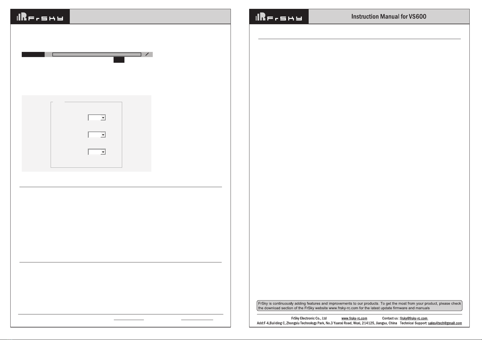
2. Channel, Operating Band and Operating Power could be set through the Upper Computer FreeLink. Connect
VS600 to the computer and configure parameters with FreeLink. The interface is below.
CH2
B
25mW
1 1
GTrans
Channel:
Band:
Power:
Param
Channel
Band
Power lever
D
A new feature introduced with VS600 is Pit Mode. It allows the user to power up their video transmitter during
race events without interfering with other users and still have the ability to change VTX settings or do some
testing.
Operation method:
Activate: Power on VS600 while holding B1. 3 Blue LEDs will flash teice and then go out, indicating that VS600
enters into Pit Mode. The operating power is less than 0.01mW and the effective distance of image transmission
is about 1m.
Deactivate: During Pit Mode, long press B1 and 3 Blue LEDs will flash twice. After that, the Blue LED which
indicates the corresponding operating power will be on. VS600 enters into normal working mode.
Pit Mode
Attention
NEVER TURN ON TRANSMITTER WITHOUT INSTALLING A PROPER ANTENNA.
The factory setup of operating state may be different.
VS600 will remember the preset operating state (channel output, operating frequency and operating
power) if it is power on again.
FCC STATEMENT
1. This device complies with Part 15 of the FCC Rules. Operation is subject to the following two conditions:
1)
This device may not cause harmful interference.
2) This device must accept any interference received, including interference that may cause undesired operation.
2. Changes or modifications not expressly approved by the party responsible for compliance could void the user's authority
to operate the equipment.
NOTE: This equipment has been tested and found to comply with the limits for a Class B digital device, pursuant to Part 15
of the FCC Rules. These limits are designed to provide reasonable protection against harmful interference in a residential
installation. This equipment generates uses and can radiate radio frequency energy and, if not installed and used in
accordance with the instructions, may cause harmful interference to radio communications. However, there is no guarantee
that interference will not occur in a particular installation. If this equipment does cause harmful interference to radio or
television reception, which can be determined by turning the equipment off and on, the user is encouraged to try to correct
the interference by one or more of the following measures:
-Reorient or relocate the receiving antenna.
-Increase the separation between the equipment and receiver.
-Connect the equipment into an outlet on a circuit different from that to which the receiver is connected.
-Consult the dealer or an experienced radio/TV technician for help.

Other FrSky Transmitter manuals

FrSky TARANIS Q X7 User manual

FrSky

FrSky TARANIS Q X7 User manual

FrSky TANDEM X20 User manual

FrSky

FrSky TANDEM X20 User manual

FrSky D8R-II plus User manual

FrSky

FrSky D8R-II plus User manual

FrSky Taranis X9D Plus User manual

FrSky

FrSky Taranis X9D Plus User manual

FrSky TANDEM X20S User manual

FrSky

FrSky TANDEM X20S User manual

FrSky Access Taranis X9 Lite User manual

FrSky

FrSky Access Taranis X9 Lite User manual

FrSky Access Taranis X9 Lite User manual

FrSky

FrSky Access Taranis X9 Lite User manual

FrSky TANDEM X20S User manual

FrSky

FrSky TANDEM X20S User manual

FrSky DHT-U User manual

FrSky

FrSky DHT-U User manual

FrSky HORUS X10S User manual

FrSky

FrSky HORUS X10S User manual

Popular Transmitter manuals by other brands

Sony DCC-FMT3 operating instructions

Sony

Sony DCC-FMT3 operating instructions

Altinex VGA to CAT-5 Transmitter Card MT103-115 user guide

Altinex

Altinex VGA to CAT-5 Transmitter Card MT103-115 user guide

Comark IOX Series Technical service bulletin

Comark

Comark IOX Series Technical service bulletin

Technaxx FMT1100BT user manual

Technaxx

Technaxx FMT1100BT user manual

Cervis TM70 Operation & installation manual

Cervis

Cervis TM70 Operation & installation manual

Zaxcom TRXLT3 user manual

Zaxcom

Zaxcom TRXLT3 user manual

Pfeiffer Vacuum RPT 100 operating instructions

Pfeiffer Vacuum

Pfeiffer Vacuum RPT 100 operating instructions

Genie Intellicode II Series instructions

Genie

Genie Intellicode II Series instructions

Feasycom FSC-BP119D product manual

Feasycom

Feasycom FSC-BP119D product manual

Motorola Omnistar GX2-DM1000B10/CH Series datasheet

Motorola

Motorola Omnistar GX2-DM1000B10/CH Series datasheet

SENTRONIC M-SYSTEM Mini-MW Series manual

SENTRONIC

SENTRONIC M-SYSTEM Mini-MW Series manual

JTS IN-64TH instruction manual

JTS

JTS IN-64TH instruction manual

MTS Systems LevelLimit Level Plus Operation manual

MTS Systems

MTS Systems LevelLimit Level Plus Operation manual

Novus NP785-50 instruction manual

Novus

Novus NP785-50 instruction manual

Hall Technologies DSCV1-70-TX user manual

Hall Technologies

Hall Technologies DSCV1-70-TX user manual

Superior Broadcast SBFM100-SS user manual

Superior Broadcast

Superior Broadcast SBFM100-SS user manual

Knick VariTrans P 41000 TRMS manual

Knick

Knick VariTrans P 41000 TRMS manual

Novus TxMiniBlock operating manual

Novus

Novus TxMiniBlock operating manual

manuals.online logo
manuals.online logoBrands
  • About & Mission
  • Contact us
  • Privacy Policy
  • Terms and Conditions

Copyright 2025 Manuals.Online. All Rights Reserved.