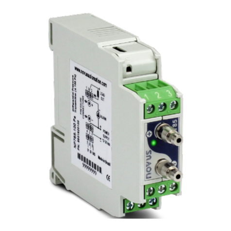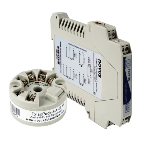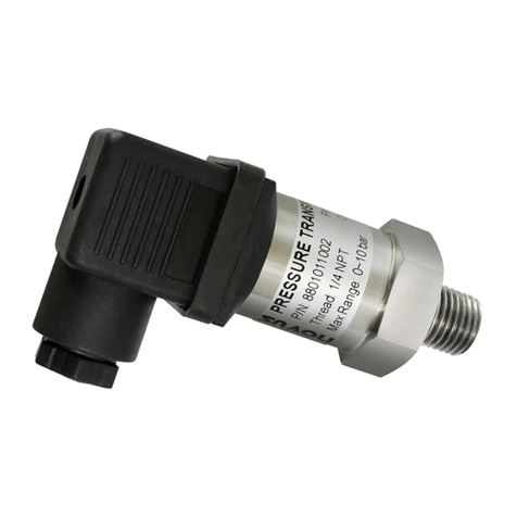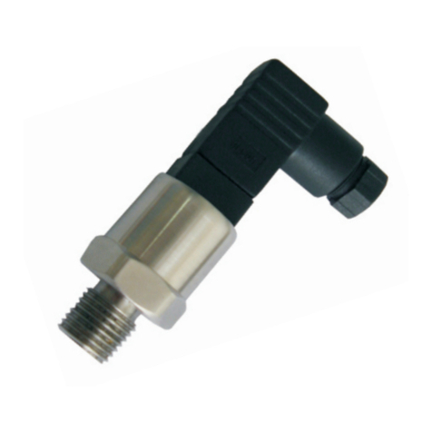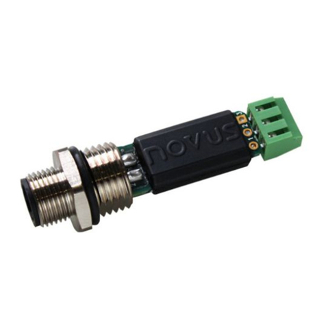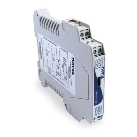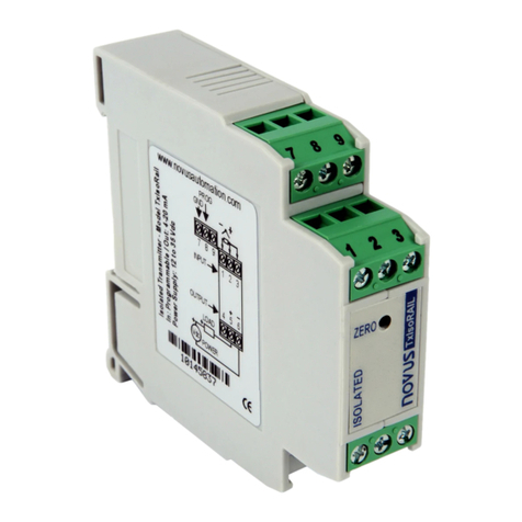
TxMiniBlock Transmitter
NOVUS AUTOMATION 2/2
3. Filtration Optimization: Filters the measurements ma e by the
transmitter eliminating interferences from the electrical system that fee s
the process.
4. Sensor Failure: Establishes the behavior of the output when problems are
presente by the sensor. When Minimum is selecte , the output current shifts
to < 4 mA ( own-scale), typically use in refrigeration. When Maximum is
selecte , if shifts to > 20 mA (up-scale), typically use for heating.
5. Zero orrection: Corrects minor errors presente by the transmitter, for
example, when the sensor is change . See item Operation in this manual.
6. Transmitter Information: In this fiel , there are ata that i entify the
transmitter. This information must be informe in any consultation with the
manufacturer.
7. Read onfiguration: When presse , this allows one to rea the
configuration on the transmitter connecte .
8. Send onfiguration: When presse , this allows one to sen the
configuration to the transmitter connecte .
Note: If, on the purchase or er, the user oes not efine a specific
configuration, the following configuration will be set:
•Pt100 sensor, range 0 to 100 °C, 0 °C zero correction.
•Filter to 60 Hz an maximum output for sensor failures.
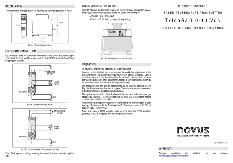
4ME HANI AL INSTALLATION
The TxMiniBlock transmitter is suitable to be installe on hea s.
Figure 04 – Transmitter imensions
5ELE TRI AL INSTALLATION
Polyami e housing for the terminals.
Section of the wire: 0.14 a 1.0 mm².
Recommen e Torque: 0.8 Nm.
RE OMMENDATIONS FOR INSTALLATION
•Input signal con uctors shoul run away from power an contactor
wires, if possible, in groun e con uits.
•The instruments must be powere by a suitable network for
instrumentation.
•System failure shoul always be taken into account when esigning a
system to avoi irreversible amage to equipment or people. Installing
RC filters (47 Ω an 100 nF, in series) is strongly recommen e at
contactor coils or any other in uctors.
ELE TRI AL ONNE TIONS
Figure 05 below shows the transmitter wiring. Terminals 1, 2 an 3 are use
for sensor input. For 2-wire Pt100, terminals 2 an 3 shall be connecte
together. The LOAD represents the input shunt of an instrument measuring
the 4-20 mA current loop.
The figure below shows the electrical connections require . Terminals 1, 2
an 3 are use for the Pt100 input. For 2-wire Pt100, terminals 2 an 3 must
be interconnecte .
Figure 05 – Transmitter electrical connections – Pt100
The LOAD represents the input shunt of an instrument measuring the 4-20
mA current loop (in icator, controller, recor er, etc).
6OPERATION
The sensor input is factory calibrate . Recalibration in the fiel is not
recommen e , but it can be accomplishe through the TxConfig software.
Contact the factory for the calibration proce ure.
When necessary, fine a justments to the transmitter output current can be
accomplishe irectly at the transmitter. To o so, short circuit transmitter
terminals 1 an 4. After 2 secon s, the output current starts to increase
gra ually until it reaches 0.8 mA above the initial value. After reaching that
value, it rops to 0.8 mA below the initial value, increasing gra ually again.
The user must monitor the output current an open the circuit when the
current reaches the esire value.
The offset correction can also be accomplishe through the TxConfig
software. The TxConfig interface can be connecte to the transmitter while it
is operating in the process. See in Figure 03 the Zero orrection fiel in the
main screen of the TxConfig software.
The user must choose the sensor span most suitable to the application. The
maximum an minimum sensor spans are limite in the TxMiniBlock an in
the TxConfig software. The user can configure any value within those two
limits.
It is important to note that the accuracy of the transmitter is always base on
the maximum range of the Pt100 sensor, regar less of the configure span. .
Example:
•Pt100 maximum span = 850 °C; 0.2% accuracy.
•Maximum error = 1.7 °C (0.2 % e 850 °C)
The error is the same no matter if total span is use (-200 to 650 °C) or a
narrower user- efine span is use , like 0 to 100 °C.
Note: When using a Pt100 simulator, make sure the TxMiniBlock’s Pt100
excitation current (0.20 mA) is compatible with the simulator specification.
7WARRANTY
The manufacturer assures the owner of the equipment, i entifie by the
purchase invoice, a twelve-month warranty as follows:
•The warranty perio starts from the ate the invoice was issue by the
manufacturer.
•Within the warranty perio , the labor an components use for the
repair are free of charge
•For any repairs, sen the equipment, along with the repair invoices, to
the manufacturer’s a ress. Costs an risks of transportation, roun
trip, will be the owner’s responsibility.
•Even uring the warranty perio , the repair of efects cause by
mechanical shock or exposure to unsuitable con itions of temperature
an humi ity will be charge .

