FTE Maximal MAX T200 HD User manual
MAX T200 HD
Ê
QUICK INSTALLATION GUIDE

MAX T200 HD
eNGlIsH
QuicK installatiOn Guide

PAG.1
rev 1.0
ENGLISH
receIVer
reMOTe cONTrOL
BATTerIeS x 2
QuIck INSTALLATION GuIde
cONTeNT

PAG. 2
rev 1.0
ENGLISH
QuIck INSTALLATION GuIde
Warning:
-The apparatus shall not be exposed to dripping or splashing and that no objects filled with liquids, such as vases,
shall be placed on the apparatus.
- Do not place naked flame sources, such as lighted candles on the apparatus; otherwise, there is the danger of
fire.
- The unit should be connected to a power supply only of the type described in the operating instructions or as
marked on the unit. If you are not sure of the type of power supply (for example: 120 or 230V) to your home, consult
your local dealer or local power company.
- Do not open the cabinet or touch any parts in the inner mechanism. Consult your local dealer for technical service
if the opening is required.
- The mains plug is used as the disconnect device, the disconnect device shall remain readily operable.
- Take attention to the environmental aspects of battery disposal. The battery of remote control should not be
exposed excessive heat such as sunshine, fire or the like.
- Maintenance man must use the appointed screw in the rear plate.
- Ensure a minimum distance of 5 cm around the apparatus for sufficient ventilation.
- Ensure that the ventilation is not impeded by covering the ventilation openings with items such as newspapers,
table-cloths, curtains, etc.
- Use the apparatus only in moderate climates (not in tropical climates).
- Do not open the cabinet to avoid the unit direct exposure to radiation.
Unit Cleaning: After the unit power is turned off, you can clean the cabinet, panel and remote control with a soft
cloth lightly moistened with a mild detergent solution.
Attachments: Never add any attachments and/or equipment without the manufacturer consent; as such additions
may result in the risk of fire, electric shock or other personal injury.
Locating: Slots and openings in the cabinet are provided for ventilation to protect it from overheating. Do not block
these openings or allow them to be blocked by placing the STB on a bed, sofa or other similar surface, nor should it
be placed over a radiator or heat register.
Power-Cord Protection: Place the power-supply cord out of the way, where it will not be walked on. Please take
special attentions to cords at plugs, convenience receptacles and the point where they exit from the unit.
Object and Liquid Entry: Never put objects of any kind into this STB through openings, as they may touch
dangerous voltage points or short-out parts that could result in a fire or electric shock. Never spill any liquid on the
STB.
Note: Moisture may be formed inside the unit in the following conditions:
When the unit is suddenly moved from a cold environment or an air-condition room to a warm place.
Immediately after a heater has been turned on.
In a steamy or very humid room.
If the moisture forms inside the unit, it may not operate properly. To correct this problem, turn on the power and wait
about two hours for the moisture to evaporate.
Parts Replacement: When the unit parts need to be replaced, user should make sure the service technician use the
replacement parts specified by the manufacturer or having the same characteristics as the original part. Unauthorized
replacement may put the unit in the risk of fire, electric shock or other hazards.
Safety Check: After all the maintenances and repairs are done, user is required to request the service technician to
conduct the overall safety check to ensure the machine is in the proper condition.
The lightning flash with
arrowhead symbol, within an
equilateral triangle, is intended
to alert the user to “dangerous
voltage” and to prevent from
a risk of electric shock
Warning: To reduce the risk of electric shock,
don’t open the cabinet. Refer servicing to
qualified personnel only.
The exclamation point
within an equilateral triangle
is intended to alert the user
to important operating and
maintenance (servicing).
Danger of explosion if battery is incorrectly replaced. Replace only with the same or equivalent type.
PAG.3
rev 1.0
ENGLISH
QuIck INSTALLATION GuIde
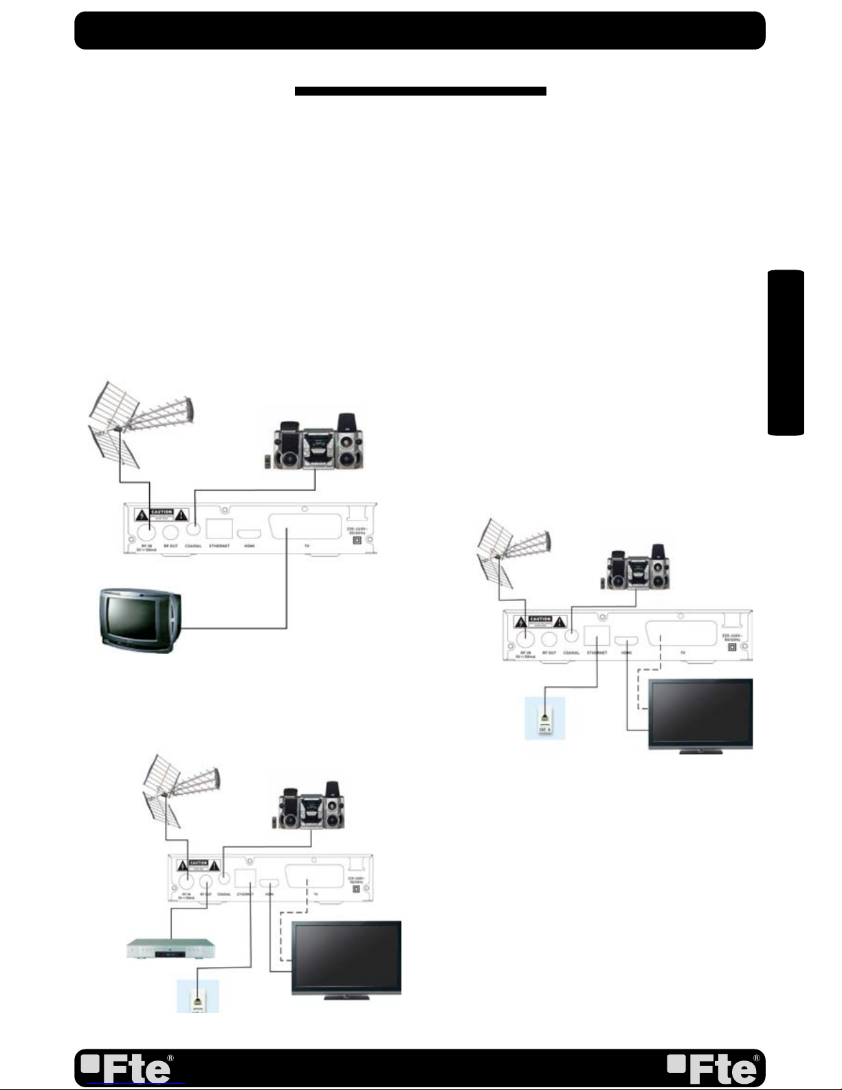
Follow next steps for the correct installation of this receiver.
STeP 1: cONNecTIONS
Connect a coaxial cable from the output socket to the “RF IN” connector. Connect a coaxial cable from
the “RF OUT” connector at the receiver to your TV input connector as it is shown in Scheme1.
This receiver has not built in modulator so it has to be connected to the TV through a HDMI or SCART
cable.
QuIck INSTALLATION GuIde
exAMPLe 2
exAMPLe 3
exAMPLe 1

PAG. 4
rev 1.0
ENGLISH
STeP 2:
OuTPuT VIdeO cONFIGurATION
The HDMI output of receiver will start in 720p mode by
default, This mode should be supported by your TV HDMI
input. Please verify in your TV manual that the HDMI input
supports this video mode. This receiver also supports
the following video modes (By origin / Native TV / 480i /
480p / 576i / 576p / 720p_50 / 720p_60 / 1080i_25 /
1080i_30 / 1080p_50 / 1080p_60). If your TV does not
support this video mode, and you want to connect by HDMI,
we recommend you first connect by scart connexion and in
the installation wizard or in the menu of the receiver change
the video mode to one suitable for connecting to your TV by
HDMI.
STeP 3: BASIc cONFIGurATION OF The
receIVer
The receiver includes an installation assistant that will help
you to setup the different parameters.
When the receiver is turned on at first time (using the button
at the rear panel of the receiver), the next menu is shown on
the TV:
In order to move through the different options of this menu,
please use the keysof the remote control. - Region: select
your country using keys.
- Region: select the language of the menu and other
information of the receiver. To choose between the different
languages, use keys of the remote control.
- Video Resolution: is used to switch the video resolution. You
can press [ ] key to select mode output video.
- Aspect Mode is used for switching the screen aspect ratio
mode. Now we provide below options: 4:3 PS (Pan and
Scan) / 4:3 LB (Letter box)/ 16:9 / AUTO. You can press [
] key to select each mode circularly.
- Auto Scan: before making an auto scan (press [OK] button)
be sure that the data of the Region option (Image 1) is
correct, in other case the search of channels will be made
wrongly. Once the Region option is confirmed, please press
[OK]. ( image 2)
Don’t make any action with the receiver until the Auto scan
has finished.
IMAGe 1
IMAGe 2
QuIck INSTALLATION GuIde

PAG.5
rev 1.0
ENGLISH
TV Channel List: This option shows the list of TV stored channels.
Radio Channel List: This option shows the list of Radio stored channels.
Delete All: This option deletes all TV and Radio stored channels.
Auto Scan: This option make a full scan of all TV and Radio channels received.
Channel Scan: This option make a compete scan of only one Multiplex.
LCN: This option can control the channel whether sort by the information in the
streams.
QuIck INSTALLATION GuIde
edIT chANNeL
INSTALLATION
Language: This option allows selecting menu and options languages.
TV System: This option allows choosing the video Standard and other parameters of the
screen.
Local Time Setting: In this option, the time of the receiver and user region or country
can be configured.
Timer Setting: Timer setting menu.
Parental Lock: In this option, user can lock the access to the menu and change the
password of the receiver.
OSD Setting: In this option, the OSD settings can be configured.
Favorite: It allows changing the name of the favourite groups.
Audio Description Setting: Its allows you setup audio description setting.
Multiview setting: This menu allows you to set multiiview screen.
Other: In this menu you can configure the “LNB power”, “Channel play Type”, “Beeper”
,“Auto Standby” and Loopthougth in standby functions.
SYSTeM SeTuP

PAG. 6
rev 1.0
ENGLISH
Information: This option shows the software information of the receiver
Load Factory Settings: If this option is selected, a reset of the receiver will be done and
it will load the factory default values.
Software Upgrade by OTA: To update the receiver by OTA.
Software Upgrade by USB: To update the receiver by USB
Remove USB device safely: Allows remove USB device of safety way.
QuIck INSTALLATION GuIde
TOOLS
Record: It allow play recordings from the usb disk.
Video: This menu permit play video from the usb disk.
Music: It allows play music from the usb disk.
Image: this menu allow show image from the usb disk.
HDD Information: You can see the capacity of the hard disk. Allows to configure the hard
disk options and to format it.
DVR Setting: It allows configuring the Timeshift activation.
MedIA PLAYer
Network: This menu allows you to set the network options, watch the weather
forecast and listen to the Net Radio
NeTwOrk

PAG.7
rev 1.0
ENGLISH
1. PANeL & reMOTe cONTrOL deScrIPTION
1.1. FrONT PANeL deScrIPTION
reMOTe cONTrOL & PANeL deScrIPTION
1. RF IN: Input of the digital tuner.
2. RF OUT: Ouput for cascading to others devices.
3. COAXIAL S/PDIF: Coaxial output for digital audio (AC3)
4. ETHERNET: Network connection of the receiver.
5. HDMI: HDMI output for connecting to a TV
6. TV SCART: Output SCART for the connection to a TV set.
7. AC IN: Mains input cable. 220-240 VAC - 50/60Hz
1.2. reAr PANeL deScrIPTION
1. DISPLAY: 4 Digits to display the program numbers.
2. Remote Sensor: Detects the infrared signals from the remote control unit.
3. STAND BY LED: Shows the state of the receiver
4. USB: USB Connector 2.0
4
321
6
2
15
37
4

PAG. 8
rev 1.0
ENGLISH
1. STANDBY: Switches receiver ON or in stand-by-mode.
2. MUTE: Switches audio on and off.
3. Numeric keys: For direct typing values and names.
4. EPG: Shows the EPG information.
5. AUDIO: Opens audio menu.
6. SUBTITLE: Switches subtitle on and off.
7. INFO: Shows channel information with signal bar.
8. RECALL: Watch the last viewed channel.
9. TV/RADIO: Switches between TV and Radio channels.
10. MENU: Opens the main menu.
11. EXIT: Exit menus or stop operations.
12. [ ]: Changes channels or controls the cursor in
menus.
13. OK: Confirms selections or opens channel list.
14. [ ]: Adjusts audio volume or controls the cursor in
menus.
15. RECORD: Quick start for recording.
16. STOP: Stop button for recording and TimeShift.
17. VOL+/-: Adjusts audio volume up and down.
18. CH+/-: Changes channel up and down.
19. TTX: Opens and closes teletext.
20. FAV: Opens favourite channel list.
21. MEDIA: Opens PVR menu.
22. PREV |<<: Back
23. PLAY: Start button for recording and TimeShift.
24. REV <<: Backward button for recording and TimeShift.
25. USB: Opens the multimedia process menu
26. NEXT >>|: Next
27. PAUSE II: Pause button for recording and TimeShift.
28. FWD >>: Forward button for recording and TimeShift.
29. Colour Keys: Controls menu options.
reMOTe cONTrOL & PANeL deScrIPTION
1.3 reMOTe cONTrOL deScrIPTION
1 2
3
4
5
6
789
10 11
12 13 14
20
15 16
17
19
18
21 22 23 24
25 26 27 28
29

ESPAÑA
Agustí Pi i Sunyer, 15
08192 Sant Quirze del Vallès
(Barcelona) España
Tel. +34 93 729 27 00
Fax. +34 93 729 30 73
www.ftemaximal.com
UNITED ARAB EMIRATES
P.O.Box 262442
BOUTIQUE VILLA #06,
2nd Floor
BEHIND KNOWLEDGE
VILLAGE MEDIA CITY
Dubai - UAE
Tel. +971 4 435 4826
Fax. +971 4 435 4889
www.ftemaximal.com
Table of contents
Other FTE Maximal Receiver manuals

FTE Maximal
FTE Maximal MAX S222E User manual

FTE Maximal
FTE Maximal MAX T115+ User manual

FTE Maximal
FTE Maximal MAX S122 User manual

FTE Maximal
FTE Maximal MAX S402PVR User manual

FTE Maximal
FTE Maximal MAX S123 HD User manual

FTE Maximal
FTE Maximal MAX T220 HD User manual

FTE Maximal
FTE Maximal MAX S101 HDMI User manual

FTE Maximal
FTE Maximal MAX S302CI User manual

FTE Maximal
FTE Maximal PVR T150 User manual

FTE Maximal
FTE Maximal MAX S93 User manual


