Manual de usuario · HCA 42 P
HCA 42 P - 1 - Versión_es_1.0 Fte maximal
Capítulo 1. Instalación.
1.1. Medidas de seguridad
1.- No situar el equipo cerca de ninguna fuente de calor.
2.- No someta al equipo a temperaturas que excedan el rango de funcionamiento del aparato.
3.- No exponga el equipo a goteos o salpicaduras.
4.- No coloque objetos que contengan líquidos sobre el equipo.
5.- Respetar las ranuras de ventilación del equipo, sin cubrirlas con ningún tipo de objeto.
6.- Mantener libre de obstáculos alrededor del equipo, mínimo un radio de 40 cm.
7.- Evitar ubicaciones con posibilidad de que se viertan líquidos en su interior, y con cambios importantes de
temperatura.
8.- Utilice el equipo sólo en climas moderados (no en los climas tropicales).
9.- Nunca retire la cubierta de la fuente de alimentación con el amplificador conectado a la red eléctrica por riesgo de
electrocución. En caso de problemas, acuda siempre a técnicos cualificados.
10.-No abrir en ningún caso con el equipo conectado a la red eléctrica.
11.-Durante el conexionado es preferible que el equipo esté desconectado de la red eléctrica.
12.-Respete las normas de seguridad eléctrica durante el montaje. Utilice materiales que cumplan con la normativa
vigente.
13.-La clavija de conexión debe estar accesible de un modo rápido y simple para una rápida desconexión.
14.-Nunca toque el enchufe con las manos mojadas. Así mismo, desconecte siempre el aparato antes de manipular las
conexiones.
15.-No ponga ningún objeto pesado sobre el equipo, puesto que podría estropearse.
16.-Si el equipo va a permanecer por mucho tiempo sin uso, es recomendable que lo desconecte de la red eléctrica.
17.-Las reparaciones y el mantenimiento del equipo debe ser realizado por técnicos de TV y radio cualificados.
1.2. Contenido de la caja
•Manual de usuario
•HCA 42 P
•Llave hexagonal
1.3. Descripción y conexiones
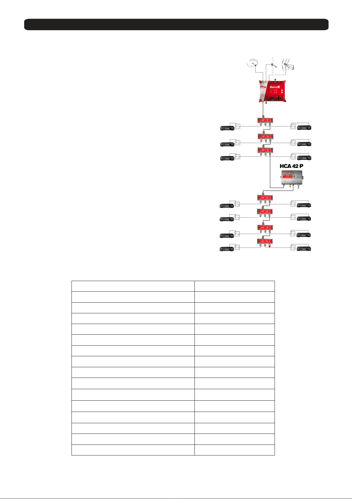
El amplificador HCA 42 P es un amplificador de línea que está diseñado para amplificar las señales de RF terrestres de
la entrada y así permitir la distribución de las mismas en la instalación. Dispone de una salida de RF y otra de test. La
salida es regulable en ganancia y en ecualización. El amplificador está diseñado para ser instalado en interiores de
edificaciones.
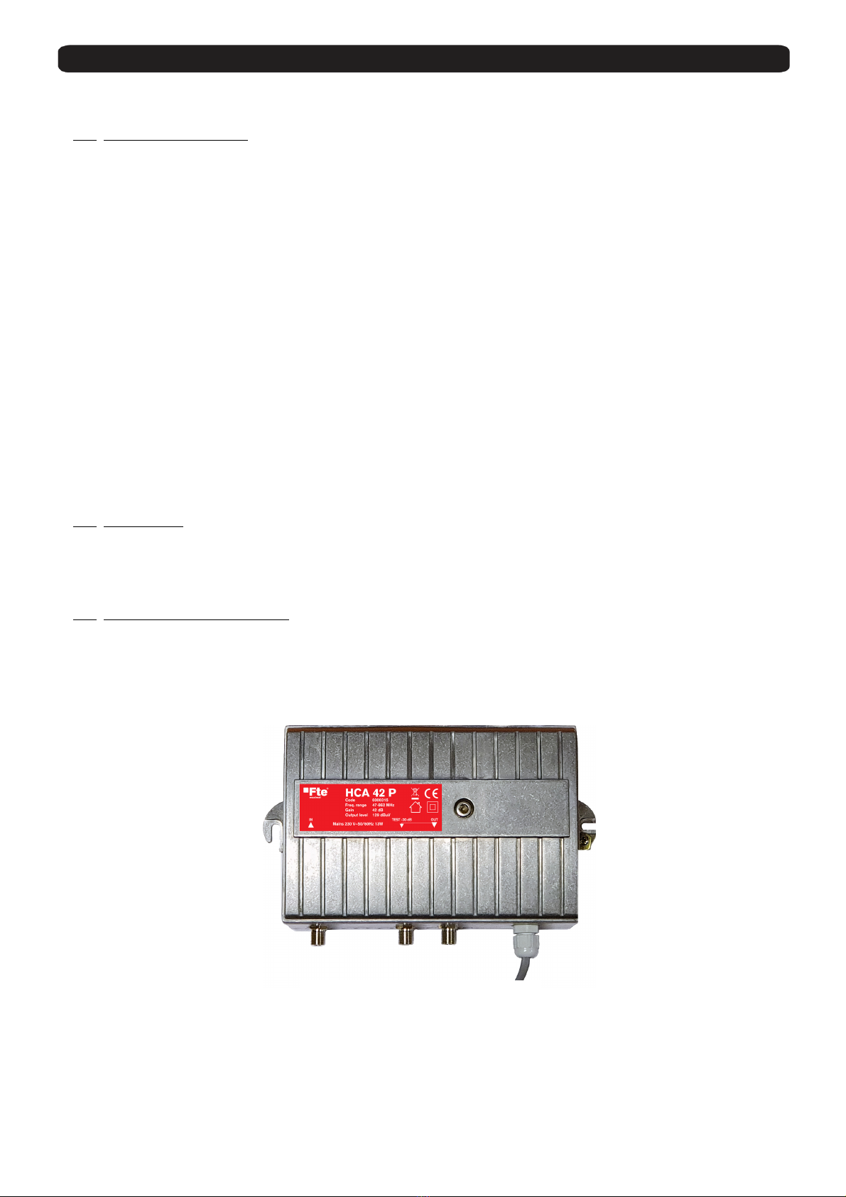
Conexiones:
1. Entrada de RF
2. Salida de Test -30 dB
3. Salida de RF
4. Toma de Tierra
5. AC IN: Cable de corriente 230Vac / 50-60Hz
1 2 3 5
4