FTS G-AFL120 User manual

Owner Manual
ATV Grass Flail Mower
G-AFL120
IMPORTANT: Read all instrucons before using this aachment
2
Congratulations on the purchase of your new attachment!
Before you get started, we have provided a helpful space to jot down a
few important details:
This manual should be considered a permanent part of this attachment
and therefore should remain with it even if the attachment is
subsequently sold.
The manufacturer continually seeks advancements in its product design
and quality. Therefore, while this manual contains the most current
product information available at the time of printing, there may be minor
discrepancies between your attachment and this manual.
If you have any questions concerning this manual, please consult your
local dealer.
Model number: G-AFL120
Serial number:
Date of purchase:
Factory reference: AT120

3
Safety Information
Before installation/maintenance, ensure vehicle and mower are
stationary and the ignition key removed. Read and understand this
manual before operating any machinery to avoid equipment
damage. Failure to follow all safety standards can result in severe
injury or death.
1. Regularly check condition and service of your mower.
2. Regularly check/tighten all bolts, nuts and screws.
3. Never consume alcohol/drugs while operating machinery.
4. Only use for the indicated purpose. Do not use to transport
personnel or livestock.
5. The engine must be stopped and the blades at a standstill, before
adjusting the mower to the transport position (raising the deck to the
highest position).
6. Always wear protective gloves, ear and eye protection and tie back
long hair. Do not wear loose clothing.
7. Check the cutting area is clear of debris that can cause damage.
8. Keep spectators at a safe distance.
9. Do not run the engine in an enclosed area.
10. Do not leave any machinery unattended while operating.
11. Do not touch moving parts. Keep hands and feet away from rotating
blades.
12. Stop the engine immediately if excessive vibration occurs.
13. Ensure the engine is switched o before any maintenance. Be aware
components can be hot after operation.
14. Pay attention to any sharp/pointed parts when servicing.
15. Always repair/replace any defective parts.
16. Do not modify the mower in any way as this may impair the
operation and overall safety.
17. Ensure all safety guards are in place and in good condition.
18. Keep all safety signs clean and legible. Replace missing/illegible signs.
4
Safety Information (continued)
Mower Pre-Use Checks
Upon receipt of your new mower and again within the rst 4 hours of use
(the ‘shake in’ period), we recommend the following:
1. Ensure the immediate area/ground is clear of debris.
2. Remove all packaging materials including wire bands/tape.
3. Check/tighten all bolts, nuts and screws (and those securing blades).
4. Check the tension of any belt (s), and adjust if required.
5. Apply grease to grease points if required.
6. Check engine oil level, top-up if required but do not overll.
7. Check fuel in tank and tyre pressures.
Vehicle Pre-Use Checks
1. Check the mower is properly attached to the vehicle and ball hitch is
secure.
2. Before installing, the vehicle and mower should be stationary,
remove the key from the ignition.
3. Install and secure all safety guards, doors and covers before
operating.
4. Bystanders should leave the immediate area before connecting the
drive from the vehicle.
Post-Use Regular Checks
Safety precaution: Be aware components can be hot after operation.
Allow drive belts/mower to cool before performing checks.
1. Check blades, belts and wearing parts. Ensure they are not damaged
and blades are secure in their mounts. Repair or replace as required.
2. Clean the attachment, and check for/clear any entangled material
around any moving parts.
3. Check rotor and roller bearings, apply grease if required.

5
Safety Information………………………………………………………………………..page 3-4
Specications…………………………………………………………………………………..page 6
Drawbar Adjustment………………………………………………………………………..page 7
Starting the Engine…………………………………………………………………………..page 8
Adjusting Roller & Side Skids …………………………………………………………..page 9
Parts Diagram 1……………………………………………………………………………..page 10
Parts List for Diagram 1…………………………………………………………….page 11-12
Parts Diagram 2……………………………………………………………………………..page 14
Parts List for Diagram 2………………………………………………………………….page 15
Contents
6
Specications
The ATV Flail Mower G-AFL model is perfect for cutting pasture and
paddock areas, ideal for maintaining a variety of grasses around the
smallholding. The mower has an independent petrol engine with tow hitch
for pulling behind an ATV. Use at a walking speed for the best cut and
nish.
Fitted with an easy to start engine, the G-AFL has been designed to cope
with a wide range of conditions. It has an easy height adjustment and a full
width anti-scalping roller to avoid damage to machine and sward.
Model Width
(cm)
Depth
(cm)
Working
Width
(cm)
G-AFL120 175 178 115 28 15hp 230

7
Before installation/maintenance, the vehicle and mower should be
stationary and the ignition key removed.
Adjust the mower drawbar to allow the mower to run directly behind the
towing vehicle.
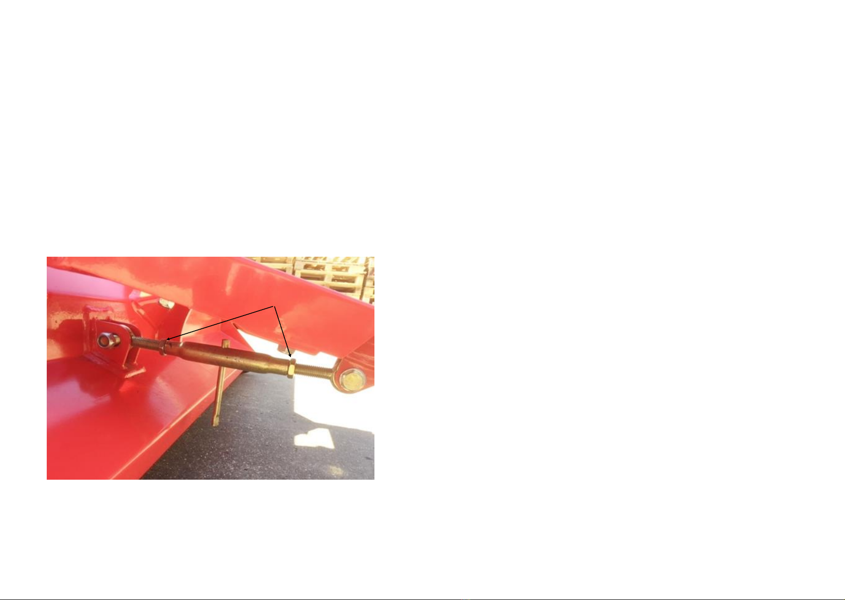
The drawbar attachment height of the towing vehicle can vary. To
accommodate adjustment, an adjustment arm is located beneath the
drawbar. This should be lengthened or shortened so that the cutting deck
is horizontal to level ground. This ensures a better nish.
Unlock the locking nuts (A), spin the arm to lengthen the link to lower the
front of the deck, or shorten to raise the deck. Once the deck is level, re-
tighten locking nuts.
Drawbar Adjustment
A
8
Starting the Engine
Before installation/maintenance, the vehicle and mower should be
stationary and the ignition key removed.
Observe all safety precautions: Keep hands and feet away from rotor/
moving parts. Keep spectators at a safe distance. Ensure there is a gap
between the blades and the ground. Select an area clear of loose debris.
Set the engine choke and suitable idling speed with the throttle. Place one
foot on top of the deck body for a rm and balanced position. Pull the
starter cord rmly, allow the cord to return to the housing slowly (one or
two strong pulls should start the engine). After a few seconds warming up
at idling speed, move the throttle to the factory pre-set working position
(see the Engine Owner Manual for full operating instructions)
NOTE: If the throttle is altered to increase the engine rpm beyond the
recommended level, the guarantee may become invalid. This may
also cause cutting ineciency, excessive vibration and an increase in
fuel consumption.
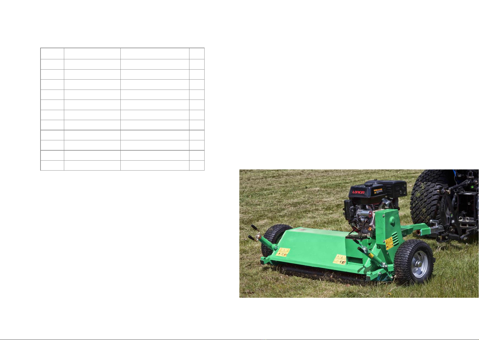
Simply hitch up the mower and turn the ignition key to start the mower.
The amount of grass/weeds dictates the forward speed. In most cases,
slow forward speeds give better results; 1 mph = very heavy use, 6 mph =
very light use. Start o in the slowest speed possible, ensure the mower is
working eciently with the engine set at maximum rpm and not
labouring. If this is not possible due to very heavy cutting conditions, raise
cutting height of blades and be prepared to go over twice with the
machine set lower on the second pass. Leave 24 hours in-between rst
and second cut to allow grass to dry out. Always listen to the engine to
ensure both engine and mower are working eciently, slow down or stop
once the engine starts to labour.
Failure to do all of the above will result in clutch slip and ultimately
severe damage to the clutch and drive belts.

9
On uneven ground, if a wheel drops into a hole, the roller takes the weight
of the mower to stop the ails scalping the ground. The roller allows the
wheel to hang over the kerb edge, so kerb side grass can be cut without
diculty. The factory pre-set position of the roller and side skids are
suitable for most situations. If used regularly on heavy grass however, the
roller and side skids should be lowered to increase the clearance between
the ail and the ground. If the mower is used as a ‘nishing mower’, the
roller can be adjusted to give the required cutting height:
To adjust the roller and skids (repeat for both ends):
1. Slacken pivot bolt ‘A’.
2. Slacken and remove bolt ‘B’.
3. Move the bracket and select another hole and replace bolt ‘B’.
4. Tighten bolts ‘A’ and ‘B’.
5. Remove the bolt at the front of the skid and the rear of the skid ‘C’.
6. Select new setting, replace the bolts and tighten. Ensure both skids
are set the same and parallel.
Adjusting Roller & Side Skids
A
B
C
Skid adjustment
Roller adjustment
10
Parts Diagram 1

11
Parts List for Diagram 1
Diag.
No Part No Description Qty
1AT120-019 Mower deck welding 1
2GB/T 5782 Bolt M16x90 1
3GB/T 5782 Bolt M20x90 1
4GB/T 97.1 Flat washer 20 2
5AT120-016A Traction connection arm 1
6GB/T 5782 Bolt M16x70 2
7GB/T 97.1 Flat washer 16 6
8AT120-016 Traction connection arm1 2
9Plastic cover 2
10 GB/T 889.1 Lock nut M12 18
11 GB/T 97.1 Flat washer 12 44
12 GB/T 5782 Bolt M12x80 4
13 AT120-017 Connection tube weldment 3
14 Adjusting bar assembling 1
15 GB/T 889.1 Lock nut M20 1
16 GB/T 889.1 Lock nut M16 1
17 AT120-102 Shaft 3
18 GB/T 97.1 Flat washer 2
19 AT120-026 Flail axle weldment 1
20 GB 13871-92 Oil seal 55x80x8 1
21 AT120-023 Skids weldment 1
22 GB/T 5783 Bolt M12x35 14
23 GB-93-87 Washer M12x25 11
24 GB/T 5783 Bolt M12x25 8
25 AT120-022 Triangle wheel protection weldment 2
26 Rotor bearing UC207 2
27 EFGC175-108 Fender 2
28 AT120-121 Shaft for fender 1
29 AT120-027 Tension roller connection 1
12
Parts List for Diagram 1 (Continued)
Diag.
No Part No Description Qty
30 GB/T 276-94 Bearing 6005-2RS 2
31 AT120-106 Bushing 1
32 AT120-108 Lower pulley 1
33 Power lock 1
34 BX41.5 V belt 2
35 Pulley cover 1
36 Wheel assembly 2
37 AT120-110 Up pulley mounting parts 1
38 AT120-111 Tension roller 1
39 GB 893.1-86 Bead ange 35 1
40 GB/T 276-94 Bearing 6007-2RS 2
41 GB 893.1-86 Bead ange 62 2
42 AT120-119 Connection shaft for clutch 1
43 AT120-109 Top pulley 1
44 Clutch 1
45 GB/T 5783 Bolt M12x30 3
46 GB/T 96.1 Bigger washer 12 3
47 AT120-021 Wheel arm (Right or Left) 2
48 AT120-015 Adjusting bar for cutting height 2
49 GB/T 1182 Grease nipple M16 2
50 GB/T 70.3-2000 Within six angles m8x25 8
51 AT120-011 Rear roller adjusting weldment plate 1
52 AT120-222 Pulley cover weldment 1
53 Roller bearing UC205 2
54 AT120-025 Rear roller weldment 1
55 GB/T 5783 Bolt M10x45 2
56 GB/T 97.1 Flat washer 10 7
57 GB/T 889.1 Lock nut M10 2
58 Engine JF420E 1
59 12v battery 1

13
Notes
14
Parts Diagram 2
1
2
3
4
5
6
5
3
2478
910
11

15
Parts List for Diagram 2
Diag. Part No Part Description Qty
1AT120-114 Wheel cap 2
2GB/T 5783 Bolt M12x30 4
3GB 93-87 Spring Washer 12 4
4GB/T 96.1 Flat gasket12 4
5GB/T 276-1994 Bearing 6205-2RS 4
6Wheel assembly 2
7GB/T 889.1 Lock nut M12 2
8AT120-021 Wheel arm (Right or Left) 2
9GB/T 97.1 Flat gasket 12 4
10 GB/T 5782 Bolt M12x80 2
11 AT120-015 Adjusting bar assembling 2
Published: August 2021
Table of contents
Other FTS Lawn Mower manuals